Page 1752 of 2453

GD(H6DO)-140
Diagnostic Trouble Code (DTC) Detecting Criteria
GENERAL DESCRIPTION
CF:DTC P0451 EVAPORATIVE EMISSION CONTROL SYSTEM PRESSURE
SENSOR
1. OUTLINE OF DIAGNOSIS
Detect the tank pressure sensor output property abnormality.
Judge NG when there is no pressure variation, which should exist in the tank, considering the engine status.
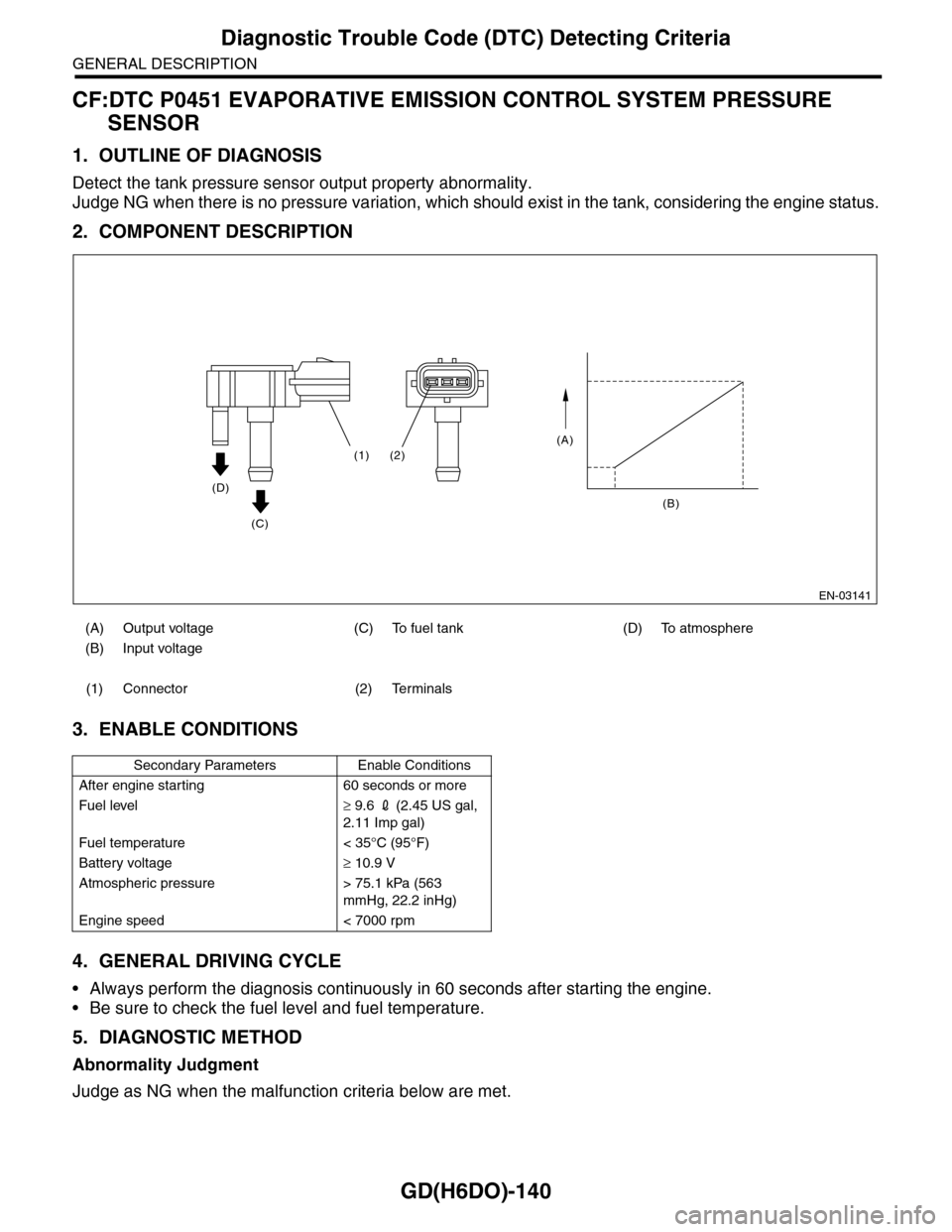
2. COMPONENT DESCRIPTION
3. ENABLE CONDITIONS
4. GENERAL DRIVING CYCLE
•Always perform the diagnosis continuously in 60 seconds after starting the engine.
•Be sure to check the fuel level and fuel temperature.
5. DIAGNOSTIC METHOD
Abnormality Judgment
Judge as NG when the malfunction criteria below are met.
(A) Output voltage (C) To fuel tank (D) To atmosphere
(B) Input voltage
(1) Connector (2) Terminals
Secondary Parameters Enable Conditions
After engine starting 60 seconds or more
Fuel level≥ 9.6 2 (2.45 US gal,
2.11 Imp gal)
Fuel temperature < 35°C (95°F)
Battery voltage≥ 10.9 V
Atmospheric pressure > 75.1 kPa (563
mmHg, 22.2 inHg)
Engine speed < 7000 rpm
EN-03141
(A)
(B)
(2)(1)
(D)
(C)
Page 1754 of 2453
GD(H6DO)-142
Diagnostic Trouble Code (DTC) Detecting Criteria
GENERAL DESCRIPTION
CG:DTC P0452 EVAPORATIVE EMISSION CONTROL SYSTEM PRESSURE
SENSOR LOW INPUT
1. OUTLINE OF DIAGNOSIS
Detect the open or short circuit of the fuel tank pressure sensor.
Judge as NG if it is out of specification.
2. COMPONENT DESCRIPTION
3. ENABLE CONDITIONS
4. GENERAL DRIVING CYCLE
Always perform the diagnosis continuously.
5. DIAGNOSTIC METHOD
Abnormality Judgment
Judge as NG when the continuous time until completing the malfunction criteria below becomes 15 seconds
or more.
Time Needed for Diagnosis: 15 seconds
Malfunction Indicator Light: Illuminates as soon as a malfunction occurs.
(A) Output voltage (C) To fuel tank (D) To atmosphere
(B) Input voltage
(1) Connector (2) Terminals
Secondary Parameters Enable Conditions
None
Judgment Value
Malfunction Criteria Threshold Value
Fuel tank pressure < –7.4 kPa (–55.85
mmHg, –2.20 inHg)
Battery voltage≥ 10.9 V
EN-03141
(A)
(B)
(2)(1)
(D)
(C)
Page 1756 of 2453
GD(H6DO)-144
Diagnostic Trouble Code (DTC) Detecting Criteria
GENERAL DESCRIPTION
CH:DTC P0453 EVAPORATIVE EMISSION CONTROL SYSTEM PRESSURE
SENSOR HIGH INPUT
1. OUTLINE OF DIAGNOSIS
Detect the open or short circuit of the fuel tank pressure sensor.
Judge as NG if it is out of specification.
2. COMPONENT DESCRIPTION
3. ENABLE CONDITIONS
4. GENERAL DRIVING CYCLE
Perform the diagnosis when purging.
(A) Output voltage (C) To fuel tank (D) To atmosphere
(B) Input voltage
(1) Connector (2) Terminals
Secondary Parameters Enable Conditions
Ve h i c l e s p e e d≥ 2 km/h (1.24 MPH)
All conditions of EVAP canister purge Completed
Learning value of evaporation gas con-
centration (left and right)
< 0.08
Main feedback compensation coefficient
(left and right)
≥ 0.9
Battery voltage≥ 10.9 V
EN-03141
(A)
(B)
(2)(1)
(D)
(C)
Page 1838 of 2453
IG(H6DO)-3
General Description
IGNITION
B: COMPONENT
C: CAUTION
•Wear work clothing, including a cap, protective goggles and protective shoes during operation.
•Remove contamination including dirt and corrosion before removal, installation or disassembly.
•Keep the disassembled parts in order and protect them from dust and dirt.
•Before removal, installation or disassembly, be sure to clarify the failure. Avoid unnecessary removal, in-
stallation, disassembly and replacement.
•Be careful not to burn yourself, because each part on the vehicle is hot after running.
•Be sure to tighten fasteners including bolts and nuts to the specified torque.
•Place shop jacks or rigid racks at the specified points.
•Before disconnecting connectors of sensors or units, be sure to disconnect the ground cable from battery.
(1) Spark plug Tightening torque: N·m (kgf-m, ft-lb)
(2) Ignition coil & ignitor ASSY T1: 16 (1.6, 11.7)
T2: 21 (2.1, 15.2)
IG-00052
(1)
(1)
(2)
(2)
T1
T2
T2
T1
Page 1839 of 2453
IG(H6DO)-4
Spark Plug
IGNITION
2. Spark Plug
A: REMOVAL
CAUTION:
All spark plugs installed on an engine must be
of the same heat range.
Spark plug:
al Description.>
1. RH SIDE
1) Remove the collector cover.
2) Disconnect the ground cable from battery.
3) Remove the air cleaner case.
Case.>
4) Remove the bracket.
5) Disconnect the connector from ignition coil.
6) Remove the ignition coil.
NOTE:
Turn the #5 ignition coil to remove it.
7) Remove the spark plug with a spark plug socket.
2. LH SIDE
1) Remove the collector cover.
2) Remove the battery and battery carrier.
3) Remove the bracket.
4) Disconnect the connector from ignition coil.
5) Remove the ignition coil.
NOTE:
Turn the #6 ignition coil to remove it.
(A) Bracket
(B) Connector
IG-02004(B)
(A)
(A) Ratchet handle
(B) Extension bar
(C) Universal joint
(D) Spark plug socket
(A) Bracket
(B) Connector
IG-02005
(D)(C)(B)(B)
(A)
IG-02011
IG-02006
(A)
(B)
Page 1845 of 2453

IN(H6DO)-3
General Description
INTAKE (INDUCTION)
B: CAUTION
•Wear work clothing, including a cap, protective
goggles and protective shoes during operation.
•Remove contamination including dirt and corro-
sion before removal, installation or disassembly.
•Keep the disassembled parts in order and pro-
tect them from dust and dirt.
•Before removal, installation or disassembly, be
sure to clarify the failure. Avoid unnecessary re-
moval, installation, disassembly and replacement.
•Be careful not to burn yourself, because each
part on the vehicle is hot after running.
•Be sure to tighten fasteners including bolts and
nuts to the specified torque.
•Place shop jacks or rigid racks at the specified
points.
•Before disconnecting connectors of sensors or
units, be sure to disconnect the ground cable from
the battery.
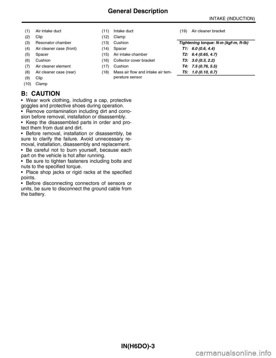
(1) Air intake duct (11) Intake duct (19) Air cleaner bracket
(2) Clip (12) Clamp
(3) Resonator chamber (13) CushionTightening torque: N·m (kgf-m, ft-lb)
(4) Air cleaner case (front) (14) SpacerT1: 6.0 (0.6, 4.4)
(5) Spacer (15) Air intake chamberT2: 6.4 (0.65, 4.7)
(6) Cushion (16) Collector cover bracketT3: 3.0 (0.3, 2.2)
(7) Air cleaner element (17) CushionT4: 7.5 (0.76, 5.5)
(8) Air cleaner case (rear) (18) Mass air flow and intake air tem-
perature sensor
T5: 1.0 (0.10, 0.7)
(9) Clip
(10) Clamp
Page 1846 of 2453
IN(H6DO)-4
Air Cleaner Element
INTAKE (INDUCTION)
2. Air Cleaner Element
A: REMOVAL
1) Disconnect the ground cable from battery.
2) Disconnect the connector from mass air flow and
intake air temperature sensor.
3) Remove the clip (A) securing upper side of air
cleaner case.
4) Pull the air cleaner case (rear) backward of the
vehicle, and remove the air cleaner element.
B: INSTALLATION
Install in the reverse order of removal.
NOTE:
Fasten with a clip after inserting the lower tab of
case.
C: INSPECTION
Replace if excessively damaged or dirty.
IN-02143
IN-02144
(A)
IN-02145
Page 1847 of 2453
IN(H6DO)-5
Air Cleaner Case
INTAKE (INDUCTION)
3. Air Cleaner Case
A: REMOVAL
1) Disconnect the ground cable from battery.
2) Remove the air intake duct.
7, REMOVAL, Air Intake Duct.>
3) Disconnect the connector from mass air flow and
intake air temperature sensor.
4) Loosen the clamps (A) which connect the air
cleaner case to intake duct.
5) Remove the clip (B) securing the upper side of
air cleaner case.
6) Remove the air cleaner case (rear) and air
cleaner element.
7) Remove the bolts (A) and nut (B) which secure
the air cleaner case to body.
8) Remove the air cleaner case (front).
B: INSTALLATION
Install in the reverse order of removal.
Tightening torque:
Bolt (A): 6.0 N·m (0.6 kgf-m, 4.4 ft-lb)
Nut (B): 7.5 N·m (0.76 kgf-m, 5.5 ft-lb)
NOTE:
Fasten with a clip after inserting the lower tab of
case.
C: INSPECTION
Check for cracks or loose connections.
IN-02143
IN-02146
(B)
(A)
IN-02148
(B)(A)
IN-02148
(B)(A)
IN-02145