Page 1600 of 2453

FU(H6DO)-39
Fuel Tank
FUEL INJECTION (FUEL SYSTEMS)
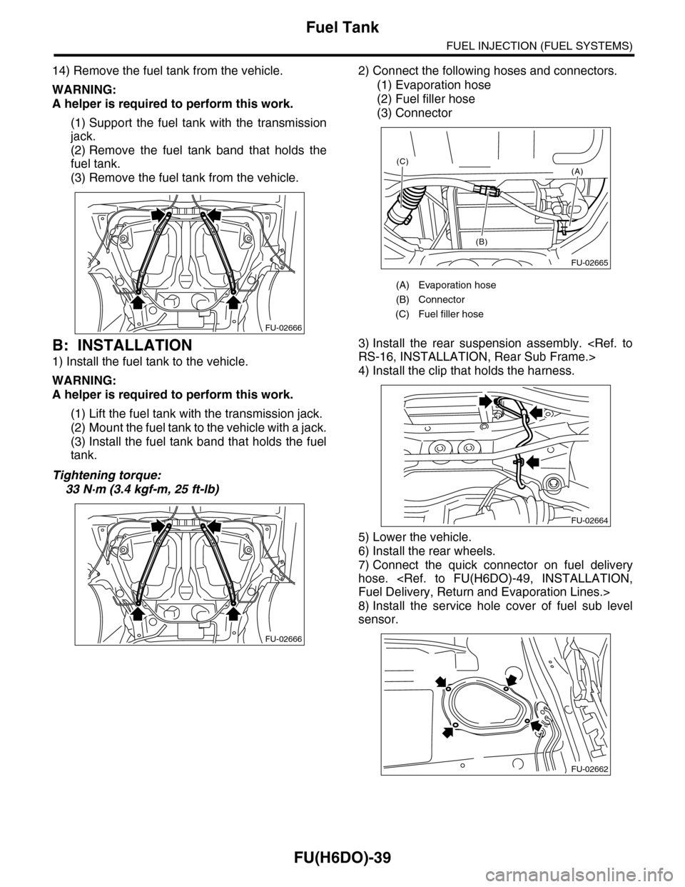
14) Remove the fuel tank from the vehicle.
WARNING:
A helper is required to perform this work.
(1) Support the fuel tank with the transmission
jack.
(2) Remove the fuel tank band that holds the
fuel tank.
(3) Remove the fuel tank from the vehicle.
B: INSTALLATION
1) Install the fuel tank to the vehicle.
WARNING:
A helper is required to perform this work.
(1) Lift the fuel tank with the transmission jack.
(2) Mount the fuel tank to the vehicle with a jack.
(3) Install the fuel tank band that holds the fuel
tank.
Tightening torque:
33 N·m (3.4 kgf-m, 25 ft-lb)
2) Connect the following hoses and connectors.
(1) Evaporation hose
(2) Fuel filler hose
(3) Connector
3) Install the rear suspension assembly.
RS-16, INSTALLATION, Rear Sub Frame.>
4) Install the clip that holds the harness.
5) Lower the vehicle.
6) Install the rear wheels.
7) Connect the quick connector on fuel delivery
hose.
Fuel Delivery, Return and Evaporation Lines.>
8) Install the service hole cover of fuel sub level
sensor.
FU-02666
FU-02666
(A) Evaporation hose
(B) Connector
(C) Fuel filler hose
FU-02665
(A)
(B)
(C)
FU-02664
FU-02662
Page 1601 of 2453
FU(H6DO)-40
Fuel Tank
FUEL INJECTION (FUEL SYSTEMS)
9) Install the service hole cover of fuel pump.
(1) Push on the grommet to install it to the sec-
ond hole cover.
(2) Tighten the bolt.
(3) Connect the connector.
10) Install the second seat.
STALLATION, Second-row Seats.>
11) Install the fuse of fuel pump to main fuse box.
12) Connect the battery ground cable to the bat-
tery.
C: INSPECTION
1) Check that the fuel tank does not have holes,
cracks or is damaged in any other way.
2) Make sure that the fuel pipe and fuel hose are
not cracked and that the connections are tight.
(A) Bolt
(B) Grommet
(C) Connector
FU-02661(A)
(A)
(B)(C)
Page 1604 of 2453

FU(H6DO)-43
Fuel Pump
FUEL INJECTION (FUEL SYSTEMS)
24.Fuel Pump
A: REMOVAL
WARNING:
•Place “NO FIRE” signs near the working area.
•Be careful not to spill fuel on the floor.
NOTE:
Fuel pump assembly consists of fuel pump and fuel
level sensor.
1) Release the fuel pressure.
37, RELEASING OF FUEL PRESSURE, PROCE-
DURE, Fuel.>
2) Drain fuel.
FUEL, PROCEDURE, Fuel.>
3) Remove the second seat.
MOVAL, Second-row Seats.>
4) Remove the service hole cover.
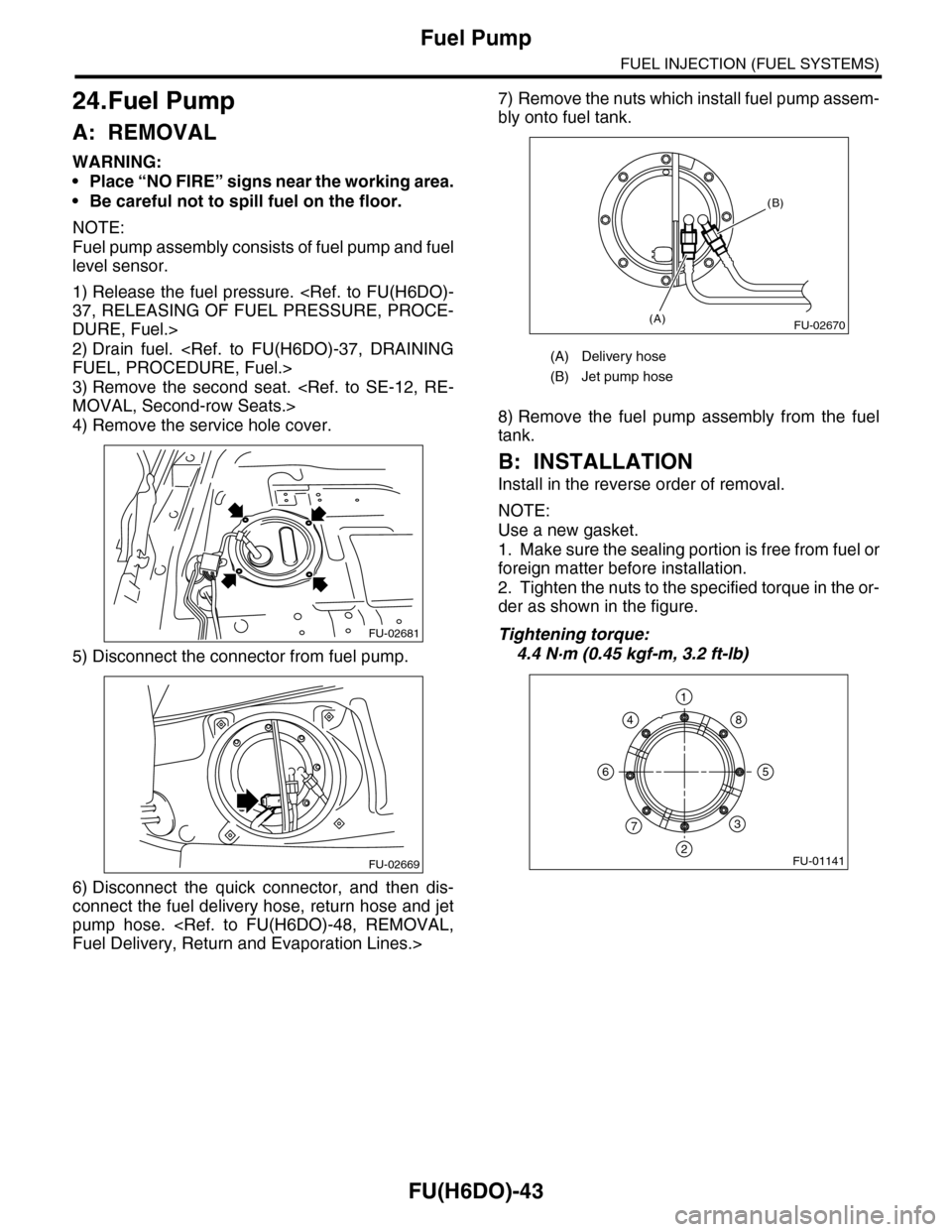
5) Disconnect the connector from fuel pump.
6) Disconnect the quick connector, and then dis-
connect the fuel delivery hose, return hose and jet
pump hose.
Fuel Delivery, Return and Evaporation Lines.>
7) Remove the nuts which install fuel pump assem-
bly onto fuel tank.
8) Remove the fuel pump assembly from the fuel
tank.
B: INSTALLATION
Install in the reverse order of removal.
NOTE:
Use a new gasket.
1. Make sure the sealing portion is free from fuel or
foreign matter before installation.
2. Tighten the nuts to the specified torque in the or-
der as shown in the figure.
Tightening torque:
4.4 N·m (0.45 kgf-m, 3.2 ft-lb)
FU-02681
FU-02669
(A) Delivery hose
(B) Jet pump hose
FU-02670(A)
(B)
FU-01141
1
2
3
4
56
7
8
Page 1605 of 2453
FU(H6DO)-44
Fuel Pump
FUEL INJECTION (FUEL SYSTEMS)
C: INSPECTION
Connect the lead harness to the connector terminal
of fuel pump, and apply the battery power supply to
check whether the pump operates.
WARNING:
•Wipe off fuel completely.
•Keep the battery as far apart from fuel pump
as possible.
•Be sure to turn the battery supply to ON and
OFF on the battery side.
•Do not run the fuel pump for a long time un-
der non-load condition.
FU-01330
246
135
Page 1606 of 2453
FU(H6DO)-45
Fuel Level Sensor
FUEL INJECTION (FUEL SYSTEMS)
25.Fuel Level Sensor
A: REMOVAL
WARNING:
•Place “NO FIRE” signs near the working area.
•Be careful not to spill fuel on the floor.
NOTE:
The fuel level sensor is built in fuel pump assembly.
1) Remove the fuel pump assembly.
FU(H6DO)-43, REMOVAL, Fuel Pump.>
2) Disconnect the connector from fuel pump brack-
et.
3) Remove the fuel temperature sensor.
4) Remove the fuel level sensor.
B: INSTALLATION
Install in the reverse order of removal.
(A) Connector
(B) Fuel temperature sensor
(C) Fuel level sensor
Page 1607 of 2453

FU(H6DO)-46
Fuel Sub Level Sensor
FUEL INJECTION (FUEL SYSTEMS)
26.Fuel Sub Level Sensor
A: REMOVAL
WARNING:
•Place “NO FIRE” signs near the working area.
•Be careful not to spill fuel on the floor.
1) Drain fuel.
FUEL, PROCEDURE, Fuel.>
2) Remove the second seat.
MOVAL, Second-row Seats.>
3) Remove the service hole cover.
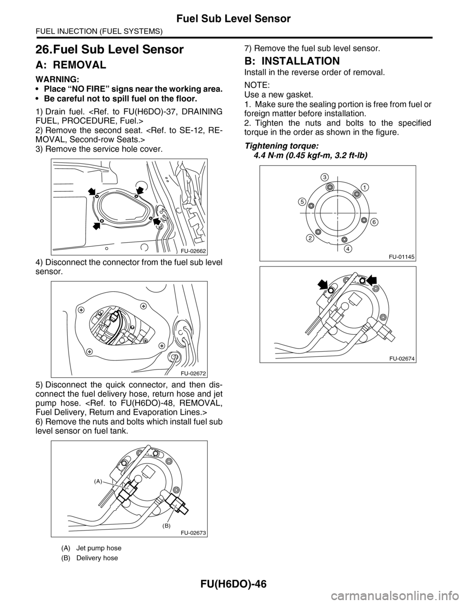
4) Disconnect the connector from the fuel sub level
sensor.
5) Disconnect the quick connector, and then dis-
connect the fuel delivery hose, return hose and jet
pump hose.
Fuel Delivery, Return and Evaporation Lines.>
6) Remove the nuts and bolts which install fuel sub
level sensor on fuel tank.
7) Remove the fuel sub level sensor.
B: INSTALLATION
Install in the reverse order of removal.
NOTE:
Use a new gasket.
1. Make sure the sealing portion is free from fuel or
foreign matter before installation.
2. Tighten the nuts and bolts to the specified
torque in the order as shown in the figure.
Tightening torque:
4.4 N·m (0.45 kgf-m, 3.2 ft-lb)
(A) Jet pump hose
(B) Delivery hose
FU-02662
FU-02672
FU-02673(B)
(A)
FU-01145
1
6
5
2
4
3
FU-02674
Page 1609 of 2453
FU(H6DO)-48
Fuel Delivery, Return and Evaporation Lines
FUEL INJECTION (FUEL SYSTEMS)
28.Fuel Delivery, Return and Evaporation Lines
A: REMOVAL
1) Set the vehicle on a lift.
2) Release the fuel pressure.
Fuel.>
3) Open the fuel filler flap lid, and remove the fuel filler cap.
4) Remove the floor mat.
5) Disconnect the fuel delivery pipe and hose and the evaporation pipe and hose.
6) In the engine compartment, disconnect the fuel
delivery hoses and evaporation hose.
(1) Disconnect the quick connector of the fuel
delivery line by pushing the ST in the direction
of the arrow.
ST 42099AE000 CONNECTOR REMOVER
(2) Remove the clip, and disconnect the evapo-
ration hose from the pipe.
WARNING:
•Be careful not to spill fuel.
•Catch the fuel from hoses using a container
or cloth.
7) Lift-up the vehicle.
8) Remove the fuel tank.
REMOVAL, Fuel Tank.>
FU-02675
Page 1610 of 2453

FU(H6DO)-49
Fuel Delivery, Return and Evaporation Lines
FUEL INJECTION (FUEL SYSTEMS)
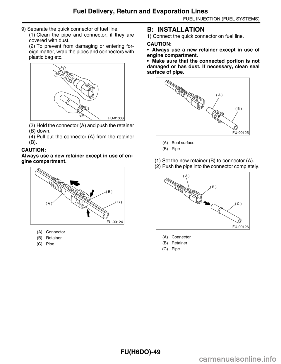
9) Separate the quick connector of fuel line.
(1) Clean the pipe and connector, if they are
covered with dust.
(2) To prevent from damaging or entering for-
eign matter, wrap the pipes and connectors with
plastic bag etc.
(3) Hold the connector (A) and push the retainer
(B) down.
(4) Pull out the connector (A) from the retainer
(B).
CAUTION:
Always use a new retainer except in use of en-
gine compartment.
B: INSTALLATION
1) Connect the quick connector on fuel line.
CAUTION:
•Always use a new retainer except in use of
engine compartment.
•Make sure that the connected portion is not
damaged or has dust. If necessary, clean seal
surface of pipe.
(1) Set the new retainer (B) to connector (A).
(2) Push the pipe into the connector completely.
(A) Connector
(B) Retainer
(C) Pipe
FU-01333
FU-00124
( A )
( B )
( C )
(A) Seal surface
(B) Pipe
(A) Connector
(B) Retainer
(C) Pipe
FU-00125
( A )
( B )
FU-00126
( A )
( B )
( C )