2009 SUBARU TRIBECA connector
[x] Cancel search: connectorPage 1544 of 2453
EN(H6DO)(diag)-383
Diagnostic Procedure with Diagnostic Trouble Code (DTC)
ENGINE (DIAGNOSTICS)
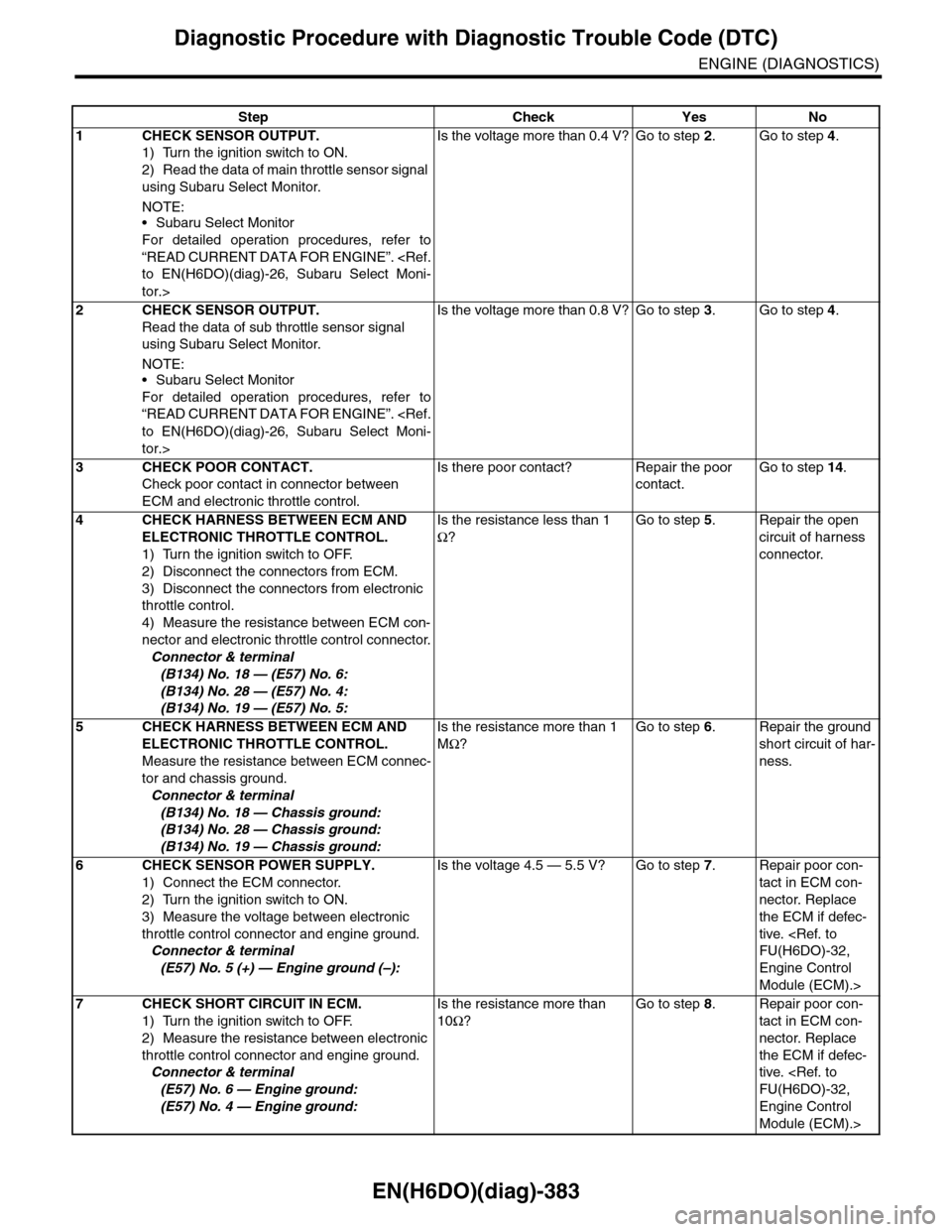
Step Check Yes No
1CHECK SENSOR OUTPUT.
1) Turn the ignition switch to ON.
2) Read the data of main throttle sensor signal
using Subaru Select Monitor.
NOTE:•Subaru Select Monitor
For detailed operation procedures, refer to
“READ CURRENT DATA FOR ENGINE”.
tor.>
Is the voltage more than 0.4 V? Go to step 2.Go to step 4.
2CHECK SENSOR OUTPUT.
Read the data of sub throttle sensor signal
using Subaru Select Monitor.
NOTE:•Subaru Select Monitor
For detailed operation procedures, refer to
“READ CURRENT DATA FOR ENGINE”.
tor.>
Is the voltage more than 0.8 V? Go to step 3.Go to step 4.
3CHECK POOR CONTACT.
Check poor contact in connector between
ECM and electronic throttle control.
Is there poor contact? Repair the poor
contact.
Go to step 14.
4CHECK HARNESS BETWEEN ECM AND
ELECTRONIC THROTTLE CONTROL.
1) Turn the ignition switch to OFF.
2) Disconnect the connectors from ECM.
3) Disconnect the connectors from electronic
throttle control.
4) Measure the resistance between ECM con-
nector and electronic throttle control connector.
Connector & terminal
(B134) No. 18 — (E57) No. 6:
(B134) No. 28 — (E57) No. 4:
(B134) No. 19 — (E57) No. 5:
Is the resistance less than 1
Ω?
Go to step 5.Repair the open
circuit of harness
connector.
5CHECK HARNESS BETWEEN ECM AND
ELECTRONIC THROTTLE CONTROL.
Measure the resistance between ECM connec-
tor and chassis ground.
Connector & terminal
(B134) No. 18 — Chassis ground:
(B134) No. 28 — Chassis ground:
(B134) No. 19 — Chassis ground:
Is the resistance more than 1
MΩ?
Go to step 6.Repair the ground
short circuit of har-
ness.
6CHECK SENSOR POWER SUPPLY.
1) Connect the ECM connector.
2) Turn the ignition switch to ON.
3) Measure the voltage between electronic
throttle control connector and engine ground.
Connector & terminal
(E57) No. 5 (+) — Engine ground (–):
Is the voltage 4.5 — 5.5 V? Go to step 7.Repair poor con-
tact in ECM con-
nector. Replace
the ECM if defec-
tive.
Engine Control
Module (ECM).>
7CHECK SHORT CIRCUIT IN ECM.
1) Turn the ignition switch to OFF.
2) Measure the resistance between electronic
throttle control connector and engine ground.
Connector & terminal
(E57) No. 6 — Engine ground:
(E57) No. 4 — Engine ground:
Is the resistance more than
10Ω?
Go to step 8.Repair poor con-
tact in ECM con-
nector. Replace
the ECM if defec-
tive.
Engine Control
Module (ECM).>
Page 1545 of 2453
EN(H6DO)(diag)-384
Diagnostic Procedure with Diagnostic Trouble Code (DTC)
ENGINE (DIAGNOSTICS)
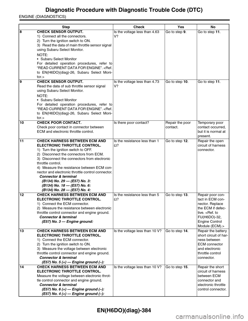
8CHECK SENSOR OUTPUT.
1) Connect all the connectors.
2) Turn the ignition switch to ON.
3) Read the data of main throttle sensor signal
using Subaru Select Monitor.
NOTE:
•Subaru Select Monitor
For detailed operation procedures, refer to
“READ CURRENT DATA FOR ENGINE”.
tor.>
Is the voltage less than 4.63
V?
Go to step 9.Go to step 11.
9CHECK SENSOR OUTPUT.
Read the data of sub throttle sensor signal
using Subaru Select Monitor.
NOTE:•Subaru Select Monitor
For detailed operation procedures, refer to
“READ CURRENT DATA FOR ENGINE”.
tor.>
Is the voltage less than 4.73
V?
Go to step 10.Go to step 11.
10 CHECK POOR CONTACT.
Check poor contact in connector between
ECM and electronic throttle control.
Is there poor contact? Repair the poor
contact.
Te m p o r a r y p o o r
contact occurred,
but it is normal at
present.
11 CHECK HARNESS BETWEEN ECM AND
ELECTRONIC THROTTLE CONTROL.
1) Turn the ignition switch to OFF.
2) Disconnect the connectors from ECM.
3) Disconnect the connectors from electronic
throttle control.
4) Measure the resistance between ECM con-
nector and electronic throttle control connector.
Connector & terminal
(B134) No. 29 — (E57) No. 3:
(B134) No. 18 — (E57) No. 6:
(B134) No. 28 — (E57) No. 4:
Is the resistance less than 1
Ω?
Go to step 12.Repair the open
circuit of harness
connector.
12 CHECK HARNESS BETWEEN ECM AND
ELECTRONIC THROTTLE CONTROL.
1) Connect the ECM connector.
2) Measure the resistance between electronic
throttle control connector and engine ground.
Connector & terminal
(E57) No. 3 — Engine ground:
Is the resistance less than 5
Ω?
Go to step 13.Repair poor con-
tact in ECM con-
nector. Replace
the ECM if defec-
tive.
Engine Control
Module (ECM).>
13 CHECK HARNESS BETWEEN ECM AND
ELECTRONIC THROTTLE CONTROL.
1) Connect the ECM connector.
2) Turn the ignition switch to ON.
3) Measure the voltage between electronic
throttle control connector and engine ground.
Connector & terminal
(E57) No. 5 (+) — Engine ground (–):
Is the voltage less than 10 V? Go to step 14.Repair the battery
short circuit of har-
ness between
ECM connector
and electronic
throttle control
connector.
14 CHECK HARNESS BETWEEN ECM AND
ELECTRONIC THROTTLE CONTROL.
Measure the voltage between electronic throt-
tle control connector and engine ground.
Connector & terminal
(E57) No. 6 (+) — Engine ground (–):
(E57) No. 4 (+) — Engine ground (–):
Is the voltage less than 10 V? Go to step 15.Repair the short
circuit of harness
between ECM
connector and
electronic throttle
control connector.
Step Check Yes No
Page 1546 of 2453
EN(H6DO)(diag)-385
Diagnostic Procedure with Diagnostic Trouble Code (DTC)
ENGINE (DIAGNOSTICS)
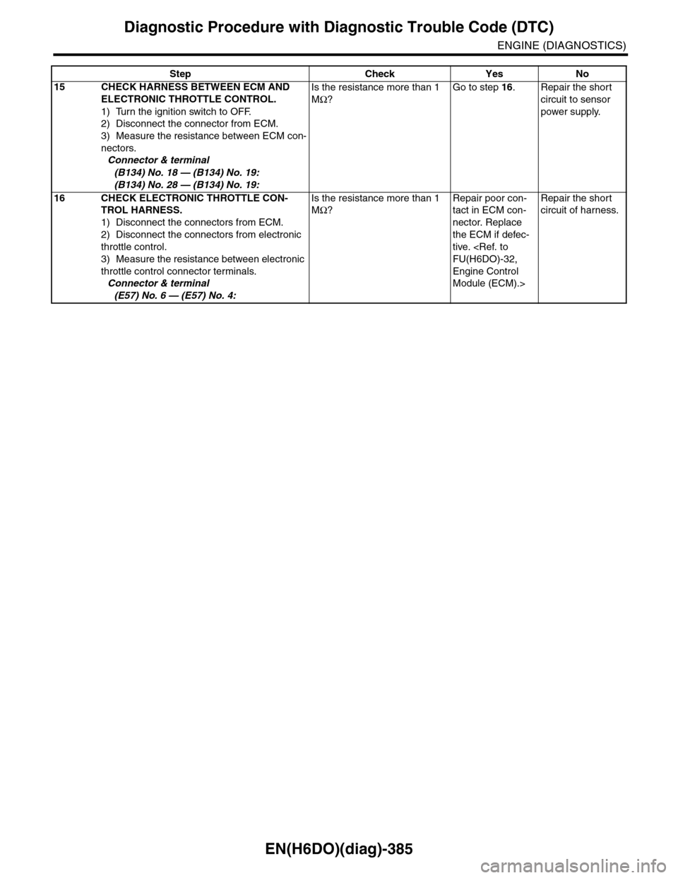
15 CHECK HARNESS BETWEEN ECM AND
ELECTRONIC THROTTLE CONTROL.
1) Turn the ignition switch to OFF.
2) Disconnect the connector from ECM.
3) Measure the resistance between ECM con-
nectors.
Connector & terminal
(B134) No. 18 — (B134) No. 19:
(B134) No. 28 — (B134) No. 19:
Is the resistance more than 1
MΩ?
Go to step 16.Repair the short
circuit to sensor
power supply.
16 CHECK ELECTRONIC THROTTLE CON-
TROL HARNESS.
1) Disconnect the connectors from ECM.
2) Disconnect the connectors from electronic
throttle control.
3) Measure the resistance between electronic
throttle control connector terminals.
Connector & terminal
(E57) No. 6 — (E57) No. 4:
Is the resistance more than 1
MΩ?
Repair poor con-
tact in ECM con-
nector. Replace
the ECM if defec-
tive.
Engine Control
Module (ECM).>
Repair the short
circuit of harness.
Step Check Yes No
Page 1548 of 2453
EN(H6DO)(diag)-387
Diagnostic Procedure with Diagnostic Trouble Code (DTC)
ENGINE (DIAGNOSTICS)
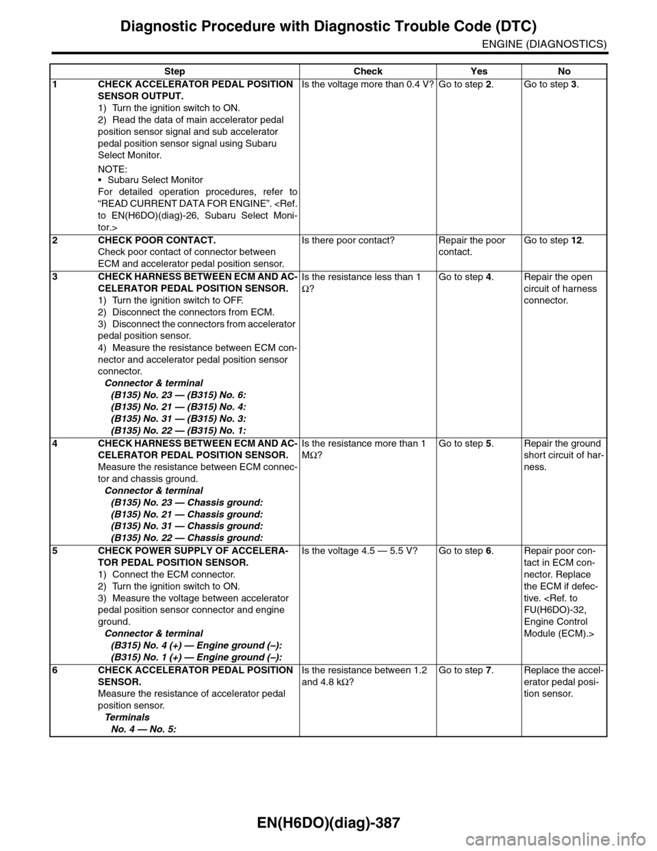
Step Check Yes No
1CHECK ACCELERATOR PEDAL POSITION
SENSOR OUTPUT.
1) Turn the ignition switch to ON.
2) Read the data of main accelerator pedal
position sensor signal and sub accelerator
pedal position sensor signal using Subaru
Select Monitor.
NOTE:•Subaru Select Monitor
For detailed operation procedures, refer to
“READ CURRENT DATA FOR ENGINE”.
tor.>
Is the voltage more than 0.4 V? Go to step 2.Go to step 3.
2CHECK POOR CONTACT.
Check poor contact of connector between
ECM and accelerator pedal position sensor.
Is there poor contact? Repair the poor
contact.
Go to step 12.
3CHECK HARNESS BETWEEN ECM AND AC-
CELERATOR PEDAL POSITION SENSOR.
1) Turn the ignition switch to OFF.
2) Disconnect the connectors from ECM.
3) Disconnect the connectors from accelerator
pedal position sensor.
4) Measure the resistance between ECM con-
nector and accelerator pedal position sensor
connector.
Connector & terminal
(B135) No. 23 — (B315) No. 6:
(B135) No. 21 — (B315) No. 4:
(B135) No. 31 — (B315) No. 3:
(B135) No. 22 — (B315) No. 1:
Is the resistance less than 1
Ω?
Go to step 4.Repair the open
circuit of harness
connector.
4CHECK HARNESS BETWEEN ECM AND AC-
CELERATOR PEDAL POSITION SENSOR.
Measure the resistance between ECM connec-
tor and chassis ground.
Connector & terminal
(B135) No. 23 — Chassis ground:
(B135) No. 21 — Chassis ground:
(B135) No. 31 — Chassis ground:
(B135) No. 22 — Chassis ground:
Is the resistance more than 1
MΩ?
Go to step 5.Repair the ground
short circuit of har-
ness.
5CHECK POWER SUPPLY OF ACCELERA-
TOR PEDAL POSITION SENSOR.
1) Connect the ECM connector.
2) Turn the ignition switch to ON.
3) Measure the voltage between accelerator
pedal position sensor connector and engine
ground.
Connector & terminal
(B315) No. 4 (+) — Engine ground (–):
(B315) No. 1 (+) — Engine ground (–):
Is the voltage 4.5 — 5.5 V? Go to step 6.Repair poor con-
tact in ECM con-
nector. Replace
the ECM if defec-
tive.
Engine Control
Module (ECM).>
6CHECK ACCELERATOR PEDAL POSITION
SENSOR.
Measure the resistance of accelerator pedal
position sensor.
Te r m i n a l s
No. 4 — No. 5:
Is the resistance between 1.2
and 4.8 kΩ?
Go to step 7.Replace the accel-
erator pedal posi-
tion sensor.
Page 1549 of 2453
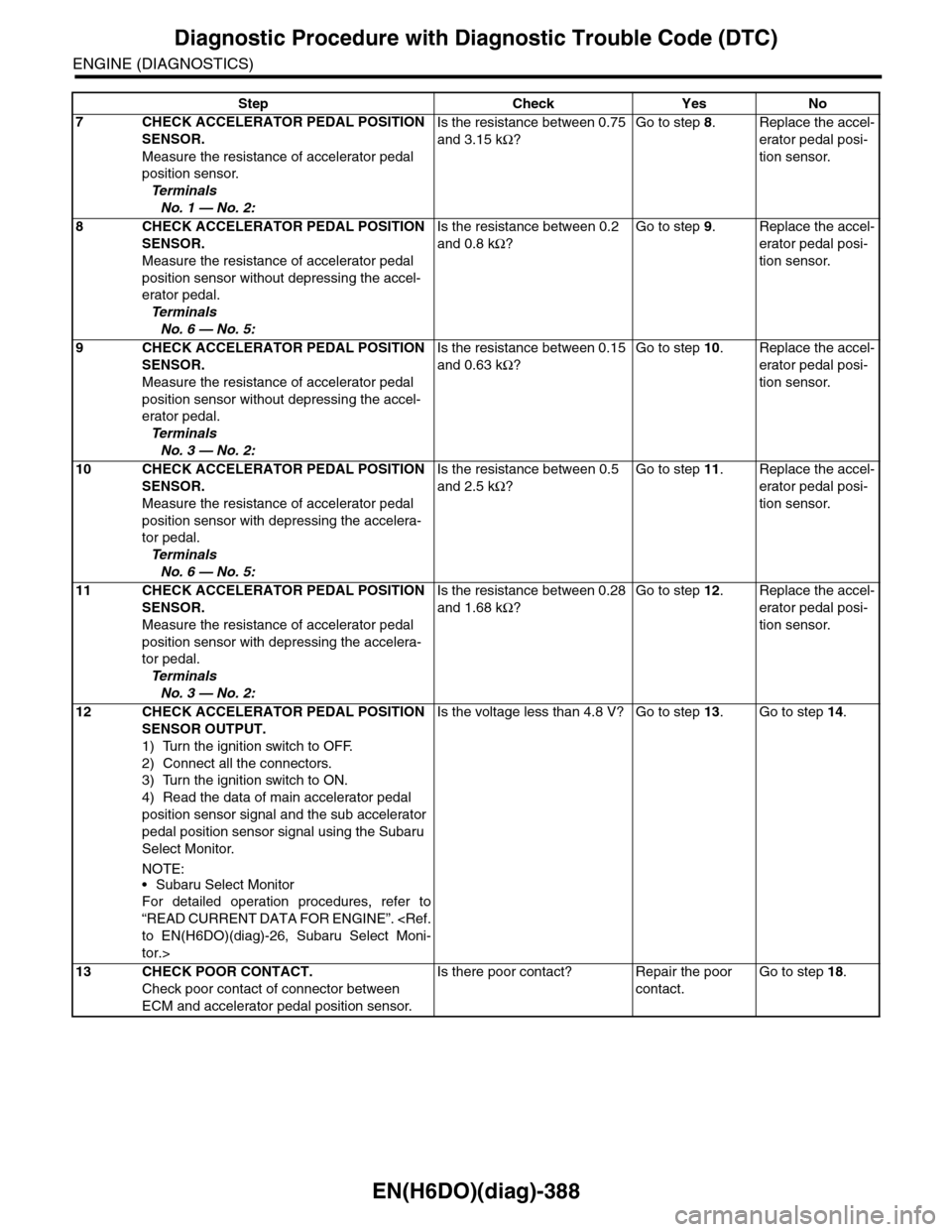
EN(H6DO)(diag)-388
Diagnostic Procedure with Diagnostic Trouble Code (DTC)
ENGINE (DIAGNOSTICS)
7CHECK ACCELERATOR PEDAL POSITION
SENSOR.
Measure the resistance of accelerator pedal
position sensor.
Te r m i n a l s
No. 1 — No. 2:
Is the resistance between 0.75
and 3.15 kΩ?
Go to step 8.Replace the accel-
erator pedal posi-
tion sensor.
8CHECK ACCELERATOR PEDAL POSITION
SENSOR.
Measure the resistance of accelerator pedal
position sensor without depressing the accel-
erator pedal.
Te r m i n a l s
No. 6 — No. 5:
Is the resistance between 0.2
and 0.8 kΩ?
Go to step 9.Replace the accel-
erator pedal posi-
tion sensor.
9CHECK ACCELERATOR PEDAL POSITION
SENSOR.
Measure the resistance of accelerator pedal
position sensor without depressing the accel-
erator pedal.
Te r m i n a l s
No. 3 — No. 2:
Is the resistance between 0.15
and 0.63 kΩ?
Go to step 10.Replace the accel-
erator pedal posi-
tion sensor.
10 CHECK ACCELERATOR PEDAL POSITION
SENSOR.
Measure the resistance of accelerator pedal
position sensor with depressing the accelera-
tor pedal.
Te r m i n a l s
No. 6 — No. 5:
Is the resistance between 0.5
and 2.5 kΩ?
Go to step 11.Replace the accel-
erator pedal posi-
tion sensor.
11 CHECK ACCELERATOR PEDAL POSITION
SENSOR.
Measure the resistance of accelerator pedal
position sensor with depressing the accelera-
tor pedal.
Te r m i n a l s
No. 3 — No. 2:
Is the resistance between 0.28
and 1.68 kΩ?
Go to step 12.Replace the accel-
erator pedal posi-
tion sensor.
12 CHECK ACCELERATOR PEDAL POSITION
SENSOR OUTPUT.
1) Turn the ignition switch to OFF.
2) Connect all the connectors.
3) Turn the ignition switch to ON.
4) Read the data of main accelerator pedal
position sensor signal and the sub accelerator
pedal position sensor signal using the Subaru
Select Monitor.
NOTE:
•Subaru Select Monitor
For detailed operation procedures, refer to
“READ CURRENT DATA FOR ENGINE”.
tor.>
Is the voltage less than 4.8 V? Go to step 13.Go to step 14.
13 CHECK POOR CONTACT.
Check poor contact of connector between
ECM and accelerator pedal position sensor.
Is there poor contact? Repair the poor
contact.
Go to step 18.
Step Check Yes No
Page 1550 of 2453
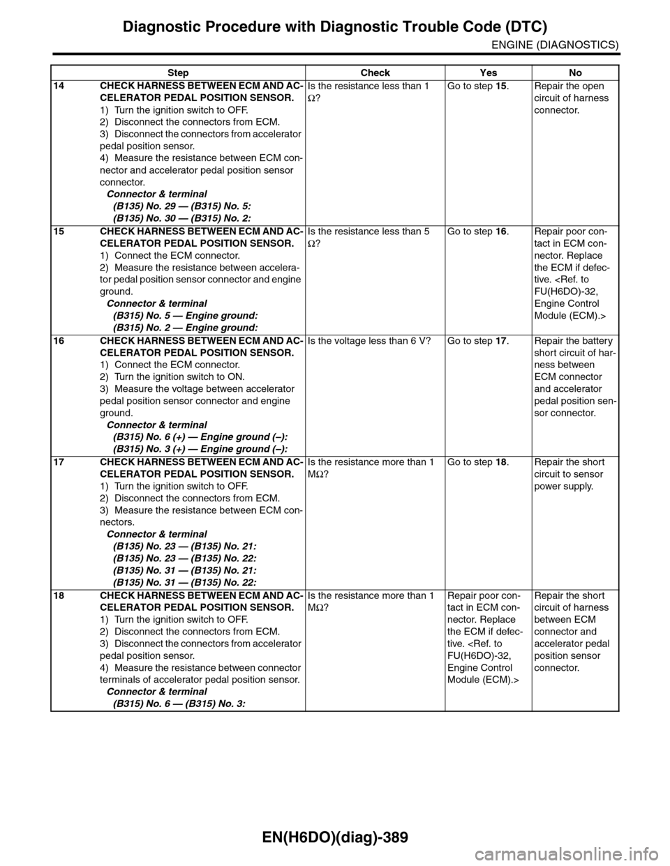
EN(H6DO)(diag)-389
Diagnostic Procedure with Diagnostic Trouble Code (DTC)
ENGINE (DIAGNOSTICS)
14 CHECK HARNESS BETWEEN ECM AND AC-
CELERATOR PEDAL POSITION SENSOR.
1) Turn the ignition switch to OFF.
2) Disconnect the connectors from ECM.
3) Disconnect the connectors from accelerator
pedal position sensor.
4) Measure the resistance between ECM con-
nector and accelerator pedal position sensor
connector.
Connector & terminal
(B135) No. 29 — (B315) No. 5:
(B135) No. 30 — (B315) No. 2:
Is the resistance less than 1
Ω?
Go to step 15.Repair the open
circuit of harness
connector.
15 CHECK HARNESS BETWEEN ECM AND AC-
CELERATOR PEDAL POSITION SENSOR.
1) Connect the ECM connector.
2) Measure the resistance between accelera-
tor pedal position sensor connector and engine
ground.
Connector & terminal
(B315) No. 5 — Engine ground:
(B315) No. 2 — Engine ground:
Is the resistance less than 5
Ω?
Go to step 16.Repair poor con-
tact in ECM con-
nector. Replace
the ECM if defec-
tive.
Engine Control
Module (ECM).>
16 CHECK HARNESS BETWEEN ECM AND AC-
CELERATOR PEDAL POSITION SENSOR.
1) Connect the ECM connector.
2) Turn the ignition switch to ON.
3) Measure the voltage between accelerator
pedal position sensor connector and engine
ground.
Connector & terminal
(B315) No. 6 (+) — Engine ground (–):
(B315) No. 3 (+) — Engine ground (–):
Is the voltage less than 6 V? Go to step 17.Repair the battery
short circuit of har-
ness between
ECM connector
and accelerator
pedal position sen-
sor connector.
17 CHECK HARNESS BETWEEN ECM AND AC-
CELERATOR PEDAL POSITION SENSOR.
1) Turn the ignition switch to OFF.
2) Disconnect the connectors from ECM.
3) Measure the resistance between ECM con-
nectors.
Connector & terminal
(B135) No. 23 — (B135) No. 21:
(B135) No. 23 — (B135) No. 22:
(B135) No. 31 — (B135) No. 21:
(B135) No. 31 — (B135) No. 22:
Is the resistance more than 1
MΩ?
Go to step 18.Repair the short
circuit to sensor
power supply.
18 CHECK HARNESS BETWEEN ECM AND AC-
CELERATOR PEDAL POSITION SENSOR.
1) Turn the ignition switch to OFF.
2) Disconnect the connectors from ECM.
3) Disconnect the connectors from accelerator
pedal position sensor.
4) Measure the resistance between connector
terminals of accelerator pedal position sensor.
Connector & terminal
(B315) No. 6 — (B315) No. 3:
Is the resistance more than 1
MΩ?
Repair poor con-
tact in ECM con-
nector. Replace
the ECM if defec-
tive.
Engine Control
Module (ECM).>
Repair the short
circuit of harness
between ECM
connector and
accelerator pedal
position sensor
connector.
Step Check Yes No
Page 1557 of 2453
EX(H6DO)-3
General Description
EXHAUST
B: CAUTION
•Wear work clothing, including a cap, protective
goggles and protective shoes during operation.
•Remove contamination including dirt and corro-
sion before removal, installation or disassembly.
•Keep the disassembled parts in order and pro-
tect them from dust and dirt.
•Before removal, installation or disassembly, be
sure to clarify the failure. Avoid unnecessary re-
moval, installation, disassembly and replacement.
•Be careful not to burn yourself, because each
part on the vehicle is hot after running.
•Be sure to tighten fasteners including bolts and
nuts to the specified torque.
•Place shop jacks or rigid racks at the specified
points.
•Before disconnecting connectors of sensors or
units, be sure to disconnect the ground cable from
battery.
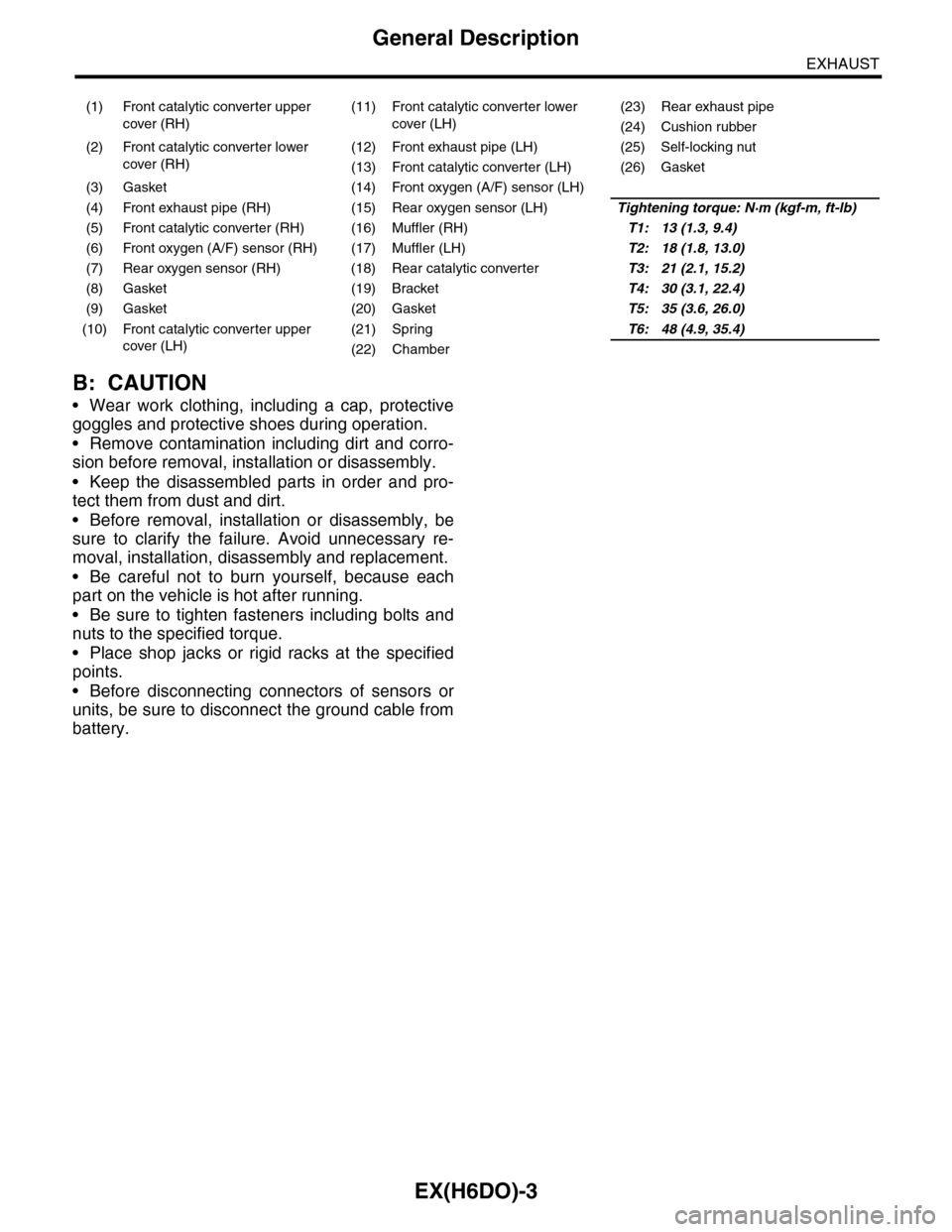
(1) Front catalytic converter upper
cover (RH)
(11) Front catalytic converter lower
cover (LH)
(23) Rear exhaust pipe
(24) Cushion rubber
(2) Front catalytic converter lower
cover (RH)
(12) Front exhaust pipe (LH) (25) Self-locking nut
(13) Front catalytic converter (LH) (26) Gasket
(3) Gasket (14) Front oxygen (A/F) sensor (LH)
(4) Front exhaust pipe (RH) (15) Rear oxygen sensor (LH)Tightening torque: N·m (kgf-m, ft-lb)
(5) Front catalytic converter (RH) (16) Muffler (RH)T1: 13 (1.3, 9.4)
(6) Front oxygen (A/F) sensor (RH) (17) Muffler (LH)T2: 18 (1.8, 13.0)
(7) Rear oxygen sensor (RH) (18) Rear catalytic converterT3: 21 (2.1, 15.2)
(8) Gasket (19) BracketT4: 30 (3.1, 22.4)
(9) Gasket (20) GasketT5: 35 (3.6, 26.0)
(10) Front catalytic converter upper
cover (LH)
(21) SpringT6: 48 (4.9, 35.4)
(22) Chamber
Page 1558 of 2453
EX(H6DO)-4
Front Exhaust Pipe
EXHAUST
2. Front Exhaust Pipe
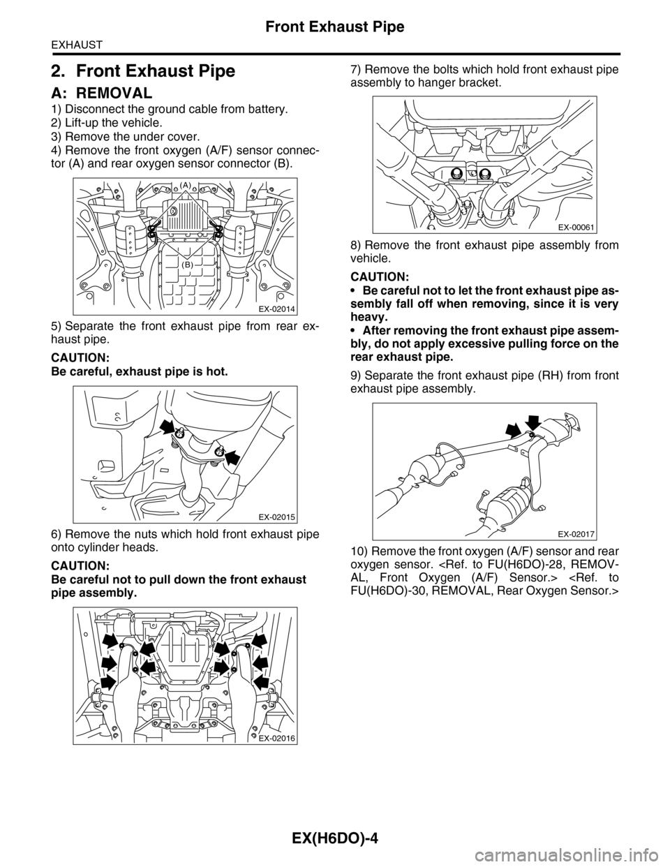
A: REMOVAL
1) Disconnect the ground cable from battery.
2) Lift-up the vehicle.
3) Remove the under cover.
4) Remove the front oxygen (A/F) sensor connec-
tor (A) and rear oxygen sensor connector (B).
5) Separate the front exhaust pipe from rear ex-
haust pipe.
CAUTION:
Be careful, exhaust pipe is hot.
6) Remove the nuts which hold front exhaust pipe
onto cylinder heads.
CAUTION:
Be careful not to pull down the front exhaust
pipe assembly.
7) Remove the bolts which hold front exhaust pipe
assembly to hanger bracket.
8) Remove the front exhaust pipe assembly from
vehicle.
CAUTION:
•Be careful not to let the front exhaust pipe as-
sembly fall off when removing, since it is very
heavy.
•After removing the front exhaust pipe assem-
bly, do not apply excessive pulling force on the
rear exhaust pipe.
9) Separate the front exhaust pipe (RH) from front
exhaust pipe assembly.
10) Remove the front oxygen (A/F) sensor and rear
oxygen sensor.
EX-02014
(A)
(B)
EX-02015
EX-02016
EX-00061
EX-02017