2009 SUBARU TRIBECA connector
[x] Cancel search: connectorPage 1453 of 2453
EN(H6DO)(diag)-292
Diagnostic Procedure with Diagnostic Trouble Code (DTC)
ENGINE (DIAGNOSTICS)
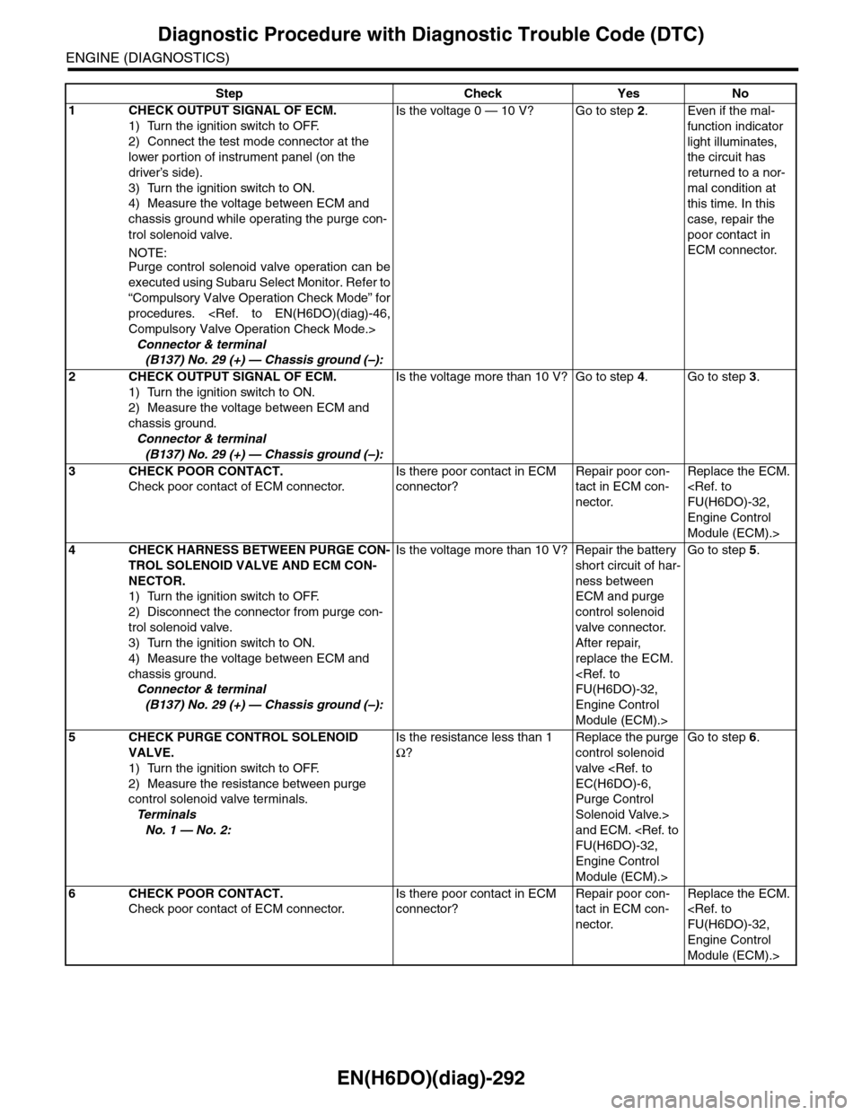
Step Check Yes No
1CHECK OUTPUT SIGNAL OF ECM.
1) Turn the ignition switch to OFF.
2) Connect the test mode connector at the
lower portion of instrument panel (on the
driver’s side).
3) Turn the ignition switch to ON.
4) Measure the voltage between ECM and
chassis ground while operating the purge con-
trol solenoid valve.
NOTE:Purge control solenoid valve operation can be
executed using Subaru Select Monitor. Refer to
“Compulsory Valve Operation Check Mode” for
procedures.
Connector & terminal
(B137) No. 29 (+) — Chassis ground (–):
Is the voltage 0 — 10 V? Go to step 2.Even if the mal-
function indicator
light illuminates,
the circuit has
returned to a nor-
mal condition at
this time. In this
case, repair the
poor contact in
ECM connector.
2CHECK OUTPUT SIGNAL OF ECM.
1) Turn the ignition switch to ON.
2) Measure the voltage between ECM and
chassis ground.
Connector & terminal
(B137) No. 29 (+) — Chassis ground (–):
Is the voltage more than 10 V? Go to step 4.Go to step 3.
3CHECK POOR CONTACT.
Check poor contact of ECM connector.
Is there poor contact in ECM
connector?
Repair poor con-
tact in ECM con-
nector.
Replace the ECM.
Engine Control
Module (ECM).>
4CHECK HARNESS BETWEEN PURGE CON-
TROL SOLENOID VALVE AND ECM CON-
NECTOR.
1) Turn the ignition switch to OFF.
2) Disconnect the connector from purge con-
trol solenoid valve.
3) Turn the ignition switch to ON.
4) Measure the voltage between ECM and
chassis ground.
Connector & terminal
(B137) No. 29 (+) — Chassis ground (–):
Is the voltage more than 10 V? Repair the battery
short circuit of har-
ness between
ECM and purge
control solenoid
valve connector.
After repair,
replace the ECM.
Engine Control
Module (ECM).>
Go to step 5.
5CHECK PURGE CONTROL SOLENOID
VALVE.
1) Turn the ignition switch to OFF.
2) Measure the resistance between purge
control solenoid valve terminals.
Te r m i n a l s
No. 1 — No. 2:
Is the resistance less than 1
Ω?
Replace the purge
control solenoid
valve
Purge Control
Solenoid Valve.>
and ECM.
Engine Control
Module (ECM).>
Go to step 6.
6CHECK POOR CONTACT.
Check poor contact of ECM connector.
Is there poor contact in ECM
connector?
Repair poor con-
tact in ECM con-
nector.
Replace the ECM.
Engine Control
Module (ECM).>
Page 1464 of 2453
EN(H6DO)(diag)-303
Diagnostic Procedure with Diagnostic Trouble Code (DTC)
ENGINE (DIAGNOSTICS)
DA:DTC P0638 THROTTLE ACTUATOR CONTROL RANGE/PERFORMANCE
(BANK 1)
NOTE:
For the diagnostic procedure, refer to DTC P2101.
tic Trouble Code (DTC).>
DB:DTC P0691 COOLING FAN 1 CONTROL CIRCUIT LOW
DTC DETECTING CONDITION:
•Detected when two consecutive driving cycles with fault occur.
•GENERAL DESCRIPTION
TROUBLE SYMPTOM:
•Radiator fan does not operate properly.
•Overheating
CAUTION:
After repair or replacement of faulty parts, perform Clear Memory Mode
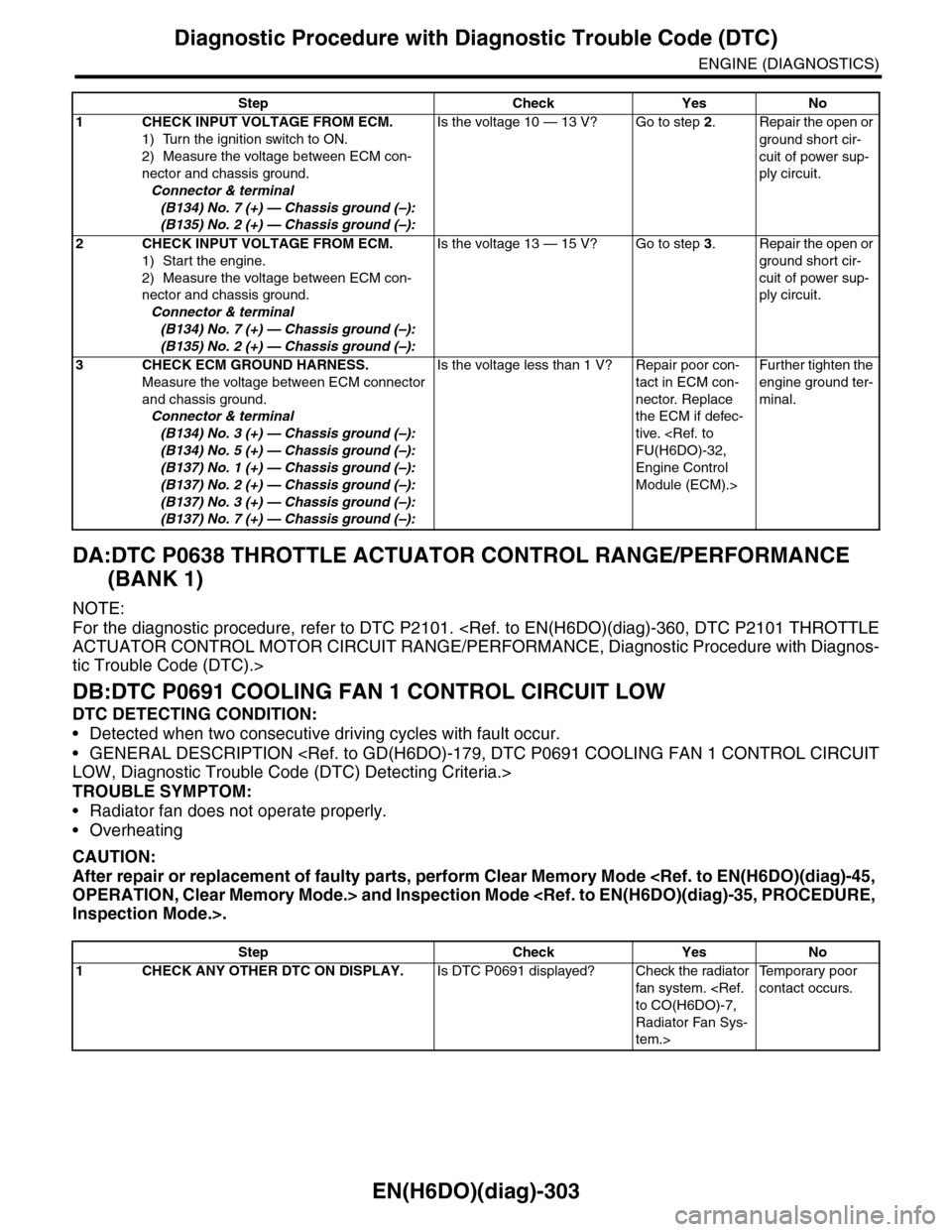
Step Check Yes No
1CHECK INPUT VOLTAGE FROM ECM.
1) Turn the ignition switch to ON.
2) Measure the voltage between ECM con-
nector and chassis ground.
Connector & terminal
(B134) No. 7 (+) — Chassis ground (–):
(B135) No. 2 (+) — Chassis ground (–):
Is the voltage 10 — 13 V? Go to step 2.Repair the open or
ground short cir-
cuit of power sup-
ply circuit.
2CHECK INPUT VOLTAGE FROM ECM.
1) Start the engine.
2) Measure the voltage between ECM con-
nector and chassis ground.
Connector & terminal
(B134) No. 7 (+) — Chassis ground (–):
(B135) No. 2 (+) — Chassis ground (–):
Is the voltage 13 — 15 V? Go to step 3.Repair the open or
ground short cir-
cuit of power sup-
ply circuit.
3CHECK ECM GROUND HARNESS.
Measure the voltage between ECM connector
and chassis ground.
Connector & terminal
(B134) No. 3 (+) — Chassis ground (–):
(B134) No. 5 (+) — Chassis ground (–):
(B137) No. 1 (+) — Chassis ground (–):
(B137) No. 2 (+) — Chassis ground (–):
(B137) No. 3 (+) — Chassis ground (–):
(B137) No. 7 (+) — Chassis ground (–):
Is the voltage less than 1 V? Repair poor con-
tact in ECM con-
nector. Replace
the ECM if defec-
tive.
Engine Control
Module (ECM).>
Fur ther tighten the
engine ground ter-
minal.
Step Check Yes No
1CHECK ANY OTHER DTC ON DISPLAY.Is DTC P0691 displayed? Check the radiator
fan system.
Radiator Fan Sys-
tem.>
Te m p o r a r y p o o r
contact occurs.
Page 1475 of 2453
EN(H6DO)(diag)-314
Diagnostic Procedure with Diagnostic Trouble Code (DTC)
ENGINE (DIAGNOSTICS)
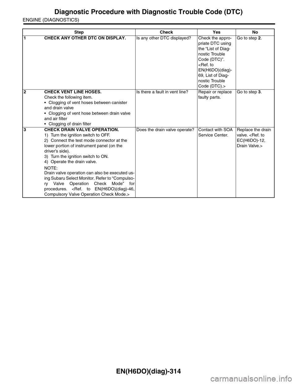
Step Check Yes No
1CHECK ANY OTHER DTC ON DISPLAY.Is any other DTC displayed? Check the appro-
priate DTC using
the “List of Diag-
nostic Trouble
Code (DTC)”.
69, List of Diag-
nostic Trouble
Code (DTC).>
Go to step 2.
2CHECK VENT LINE HOSES.
Check the following item.
•Clogging of vent hoses between canister
and drain valve
•Clogging of vent hose between drain valve
and air filter
•Clogging of drain filter
Is there a fault in vent line? Repair or replace
faulty par ts.
Go to step 3.
3CHECK DRAIN VALVE OPERATION.
1) Turn the ignition switch to OFF.
2) Connect the test mode connector at the
lower portion of instrument panel (on the
driver’s side).
3) Turn the ignition switch to ON.
4) Operate the drain valve.
NOTE:Drain valve operation can also be executed us-
ing Subaru Select Monitor. Refer to “Compulso-
ry Valve Operation Check Mode” for
procedures.
Does the drain valve operate? Contact with SOA
Service Center.
Replace the drain
valve.
Drain Valve.>
Page 1479 of 2453
EN(H6DO)(diag)-318
Diagnostic Procedure with Diagnostic Trouble Code (DTC)
ENGINE (DIAGNOSTICS)
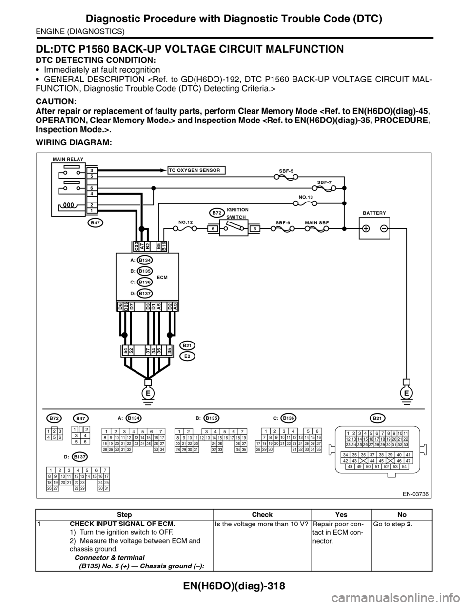
DL:DTC P1560 BACK-UP VOLTAGE CIRCUIT MALFUNCTION
DTC DETECTING CONDITION:
•Immediately at fault recognition
•GENERAL DESCRIPTION
CAUTION:
After repair or replacement of faulty parts, perform Clear Memory Mode
WIRING DIAGRAM:
EN-03736
SBF-6MAIN SBF
SBF-7
B72
B2A7C23
D7D3D1A5
B5B19
NO.12B47
E2
B21
12
46
53
ECM
EE
36
B134A:
D:B137
B135B:
B136C:
A3
52373634
3412
56
B47
TO OXYGEN SENSOR
NO.13
D2
35
B21
123412131415567816171819910 1120212223 24 25 2627 28 29 3031 32 33
3534 37363938 41404342 4445 47464948 51505352 54
B72
134562
B134
56 7821943102422 23 2511 12 13 14 1526 2728
16 1718 19 20 2133 34293230 31
A:B135
567821943102422 23 2511 12 13 14 1526 2728
16 17 18 1920 2129 30 31 32 33 34 35
B:
B137
5678219431022 2311 12 13 14 1524 2526
16 1718 19 20 2127 28 29 30 31
D:
SBF-5
D6D26
54
MAIN RELAY
BATTERYIGNITIONSWITCH
B136
16101112131415252430
9871718192028212223293231
123456
2726333435
C:
Step Check Yes No
1CHECK INPUT SIGNAL OF ECM.
1) Turn the ignition switch to OFF.
2) Measure the voltage between ECM and
chassis ground.
Connector & terminal
(B135) No. 5 (+) — Chassis ground (–):
Is the voltage more than 10 V? Repair poor con-
tact in ECM con-
nector.
Go to step 2.
Page 1480 of 2453
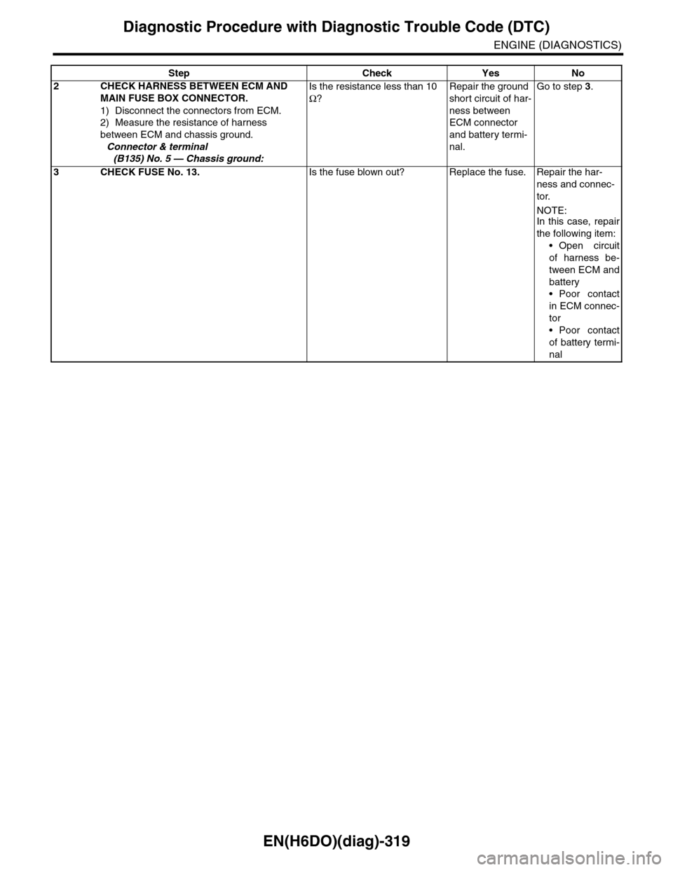
EN(H6DO)(diag)-319
Diagnostic Procedure with Diagnostic Trouble Code (DTC)
ENGINE (DIAGNOSTICS)
2CHECK HARNESS BETWEEN ECM AND
MAIN FUSE BOX CONNECTOR.
1) Disconnect the connectors from ECM.
2) Measure the resistance of harness
between ECM and chassis ground.
Connector & terminal
(B135) No. 5 — Chassis ground:
Is the resistance less than 10
Ω?
Repair the ground
short circuit of har-
ness between
ECM connector
and battery termi-
nal.
Go to step 3.
3CHECK FUSE No. 13.Is the fuse blown out? Replace the fuse. Repair the har-
ness and connec-
tor.
NOTE:In this case, repair
the following item:
•Open circuit
of harness be-
tween ECM and
battery
•Poor contact
in ECM connec-
tor
•Poor contact
of battery termi-
nal
Step Check Yes No
Page 1482 of 2453
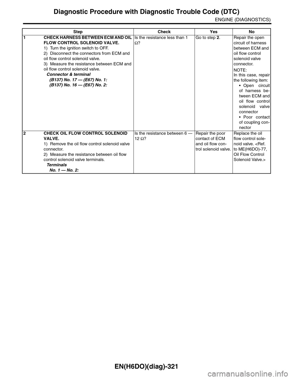
EN(H6DO)(diag)-321
Diagnostic Procedure with Diagnostic Trouble Code (DTC)
ENGINE (DIAGNOSTICS)
Step Check Yes No
1CHECK HARNESS BETWEEN ECM AND OIL
FLOW CONTROL SOLENOID VALVE.
1) Turn the ignition switch to OFF.
2) Disconnect the connectors from ECM and
oil flow control solenoid valve.
3) Measure the resistance between ECM and
oil flow control solenoid valve.
Connector & terminal
(B137) No. 17 — (E67) No. 1:
(B137) No. 16 — (E67) No. 2:
Is the resistance less than 1
Ω?
Go to step 2.Repair the open
circuit of harness
between ECM and
oil flow control
solenoid valve
connector.
NOTE:In this case, repair
the following item:
•Open circuit
of harness be-
tween ECM and
oil flow control
solenoid valve
connector
•Poor contact
of coupling con-
nector
2CHECK OIL FLOW CONTROL SOLENOID
VALVE.
1) Remove the oil flow control solenoid valve
connector.
2) Measure the resistance between oil flow
control solenoid valve terminals.
Te r m i n a l s
No. 1 — No. 2:
Is the resistance between 6 —
12 Ω?
Repair the poor
contact of ECM
and oil flow con-
trol solenoid valve.
Replace the oil
flow control sole-
noid valve.
Oil Flow Control
Solenoid Valve.>
Page 1484 of 2453
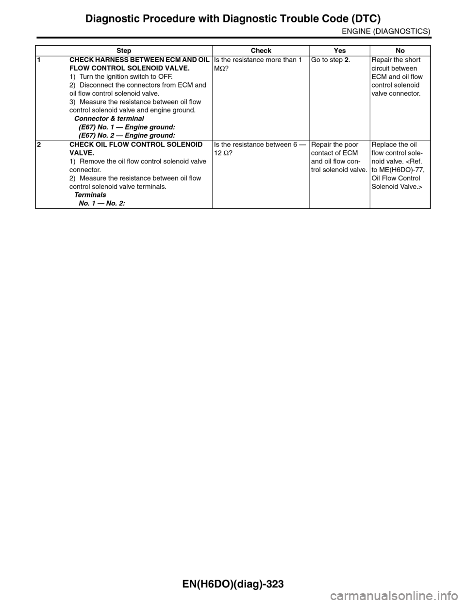
EN(H6DO)(diag)-323
Diagnostic Procedure with Diagnostic Trouble Code (DTC)
ENGINE (DIAGNOSTICS)
Step Check Yes No
1CHECK HARNESS BETWEEN ECM AND OIL
FLOW CONTROL SOLENOID VALVE.
1) Turn the ignition switch to OFF.
2) Disconnect the connectors from ECM and
oil flow control solenoid valve.
3) Measure the resistance between oil flow
control solenoid valve and engine ground.
Connector & terminal
(E67) No. 1 — Engine ground:
(E67) No. 2 — Engine ground:
Is the resistance more than 1
MΩ?
Go to step 2.Repair the short
circuit between
ECM and oil flow
control solenoid
valve connector.
2CHECK OIL FLOW CONTROL SOLENOID
VALVE.
1) Remove the oil flow control solenoid valve
connector.
2) Measure the resistance between oil flow
control solenoid valve terminals.
Te r m i n a l s
No. 1 — No. 2:
Is the resistance between 6 —
12 Ω?
Repair the poor
contact of ECM
and oil flow con-
trol solenoid valve.
Replace the oil
flow control sole-
noid valve.
Oil Flow Control
Solenoid Valve.>
Page 1486 of 2453
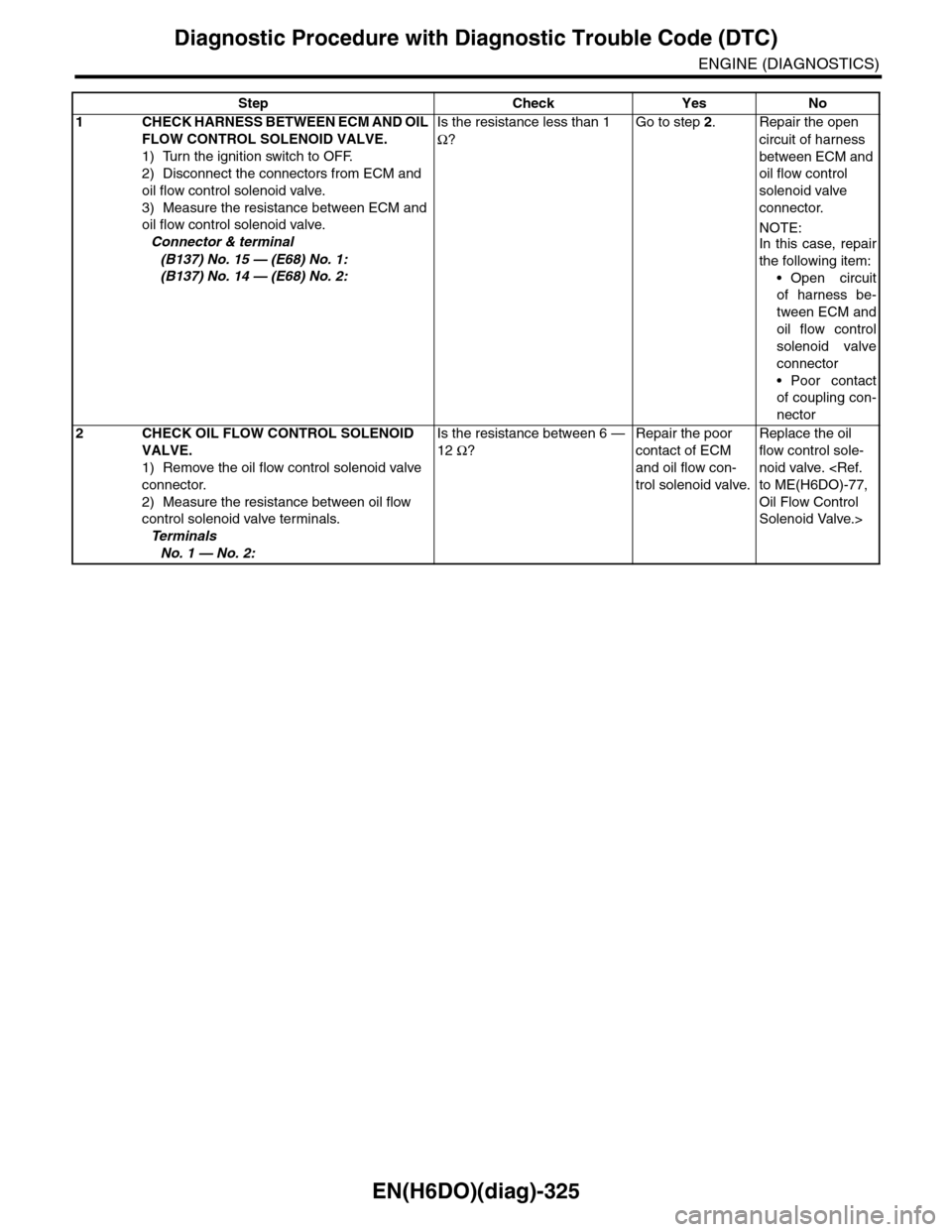
EN(H6DO)(diag)-325
Diagnostic Procedure with Diagnostic Trouble Code (DTC)
ENGINE (DIAGNOSTICS)
Step Check Yes No
1CHECK HARNESS BETWEEN ECM AND OIL
FLOW CONTROL SOLENOID VALVE.
1) Turn the ignition switch to OFF.
2) Disconnect the connectors from ECM and
oil flow control solenoid valve.
3) Measure the resistance between ECM and
oil flow control solenoid valve.
Connector & terminal
(B137) No. 15 — (E68) No. 1:
(B137) No. 14 — (E68) No. 2:
Is the resistance less than 1
Ω?
Go to step 2.Repair the open
circuit of harness
between ECM and
oil flow control
solenoid valve
connector.
NOTE:In this case, repair
the following item:
•Open circuit
of harness be-
tween ECM and
oil flow control
solenoid valve
connector
•Poor contact
of coupling con-
nector
2CHECK OIL FLOW CONTROL SOLENOID
VALVE.
1) Remove the oil flow control solenoid valve
connector.
2) Measure the resistance between oil flow
control solenoid valve terminals.
Te r m i n a l s
No. 1 — No. 2:
Is the resistance between 6 —
12 Ω?
Repair the poor
contact of ECM
and oil flow con-
trol solenoid valve.
Replace the oil
flow control sole-
noid valve.
Oil Flow Control
Solenoid Valve.>