Page 1892 of 2453
ME(H6DO)-26
Fuel Pressure
MECHANICAL
7. Fuel Pressure
A: INSPECTION
WARNING:
Before removing the fuel pressure gauge, re-
lease the fuel pressure.
1) Release the fuel pressure.
PRESSURE, PROCEDURE, Fuel.>
2) Disconnect the fuel delivery hose and connect
fuel pressure gauge.
(1) Disconnect the fuel delivery hose using the
ST1.
ST1 42099AE000 CONNECTOR REMOVER
(2) Connect the fuel pressure meter using the
ST2 and ST3.
NOTE:
ST2 is a genuine Subaru part.
ST2 42075AG690 FUEL HOSE
ST3 18471AA000 FUEL PIPE ADAPTER
3) Install the fuse of fuel pump to main fuse box.
4) Start the engine.
5) Measure the fuel pressure after warming up the
engine.
Fuel pressure:
Standard: 338 — 348 kPa (3.4 — 3.5 kgf/cm2,
49 — 50.5 psi)
NOTE:
The fuel pressure gauge registers 10 to 20 kPa (0.1
to 0.2 kgf/cm2, 1 to 3 psi) higher than standard val-
ues during high-altitude operations.
(A) ST 2
(B) ST 3
ME-02666
(A)
(B)
FU-01122
Page 1893 of 2453
ME(H6DO)-27
Valve Clearance
MECHANICAL
8. Valve Clearance
A: INSPECTION
Inspection and adjustment of valve clearance
should be performed while engine is cold.
1) Set the vehicle on a lift.
2) Remove the collector cover.
3) Disconnect the ground cable from battery.
4) Lift-up the vehicle.
5) Remove the under cover.
6) Lower the vehicle.
7) When inspecting RH side cylinders:
(1) Remove the air intake duct and air cleaner
case.
take Duct.>
Air Cleaner Case.>
(2) Remove the fuel tank protector (RH).
(3) Disconnect the connector of oil pressure
switch.
(4) Remove the ignition coil.
IG(H6DO)-7, REMOVAL, Ignition Coil & Ignitor
Assembly.>
(5) Remove the rocker cover (RH).
8) When inspecting LH side cylinders:
(1) Disconnect the battery cable, and then re-
move the battery and battery carrier.
(2) Disconnect the PCV hose and blow-by hose
from rocker cover (LH).
(3) Remove the fuel pipe protector (LH).
(4) Remove the ignition coil.
IG(H6DO)-7, REMOVAL, Ignition Coil & Ignitor
Assembly.>
(5) Remove the rocker cover (LH).
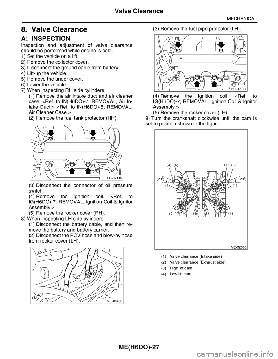
9) Turn the crankshaft clockwise until the cam is
set to position shown in the figure.
FU-02119
ME-00460
(1) Valve clearance (Intake side)
(2) Valve clearance (Exhaust side)
(3) High lift cam
(4) Low lift cam
FU-02117
ME-02565
(4)(3)(3)(4)
(1)
(2)
(1)
(2)
(23 )(23 )
Page 1898 of 2453
ME(H6DO)-32
Engine Assembly
MECHANICAL
10.Engine Assembly
A: REMOVAL
1) Set the vehicle on a lift.
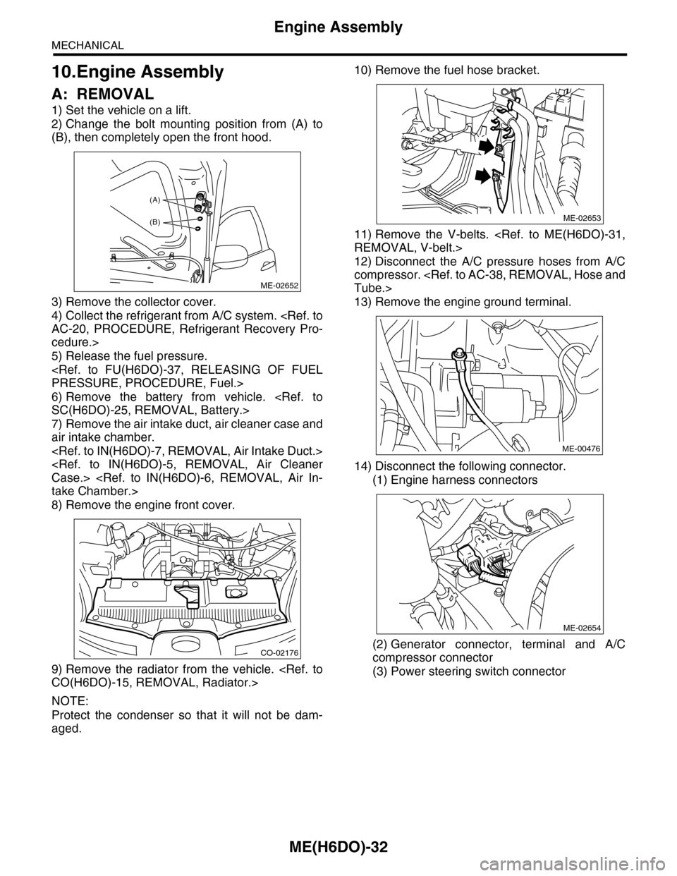
2) Change the bolt mounting position from (A) to
(B), then completely open the front hood.
3) Remove the collector cover.
4) Collect the refrigerant from A/C system.
AC-20, PROCEDURE, Refrigerant Recovery Pro-
cedure.>
5) Release the fuel pressure.
PRESSURE, PROCEDURE, Fuel.>
6) Remove the battery from vehicle.
SC(H6DO)-25, REMOVAL, Battery.>
7) Remove the air intake duct, air cleaner case and
air intake chamber.
Case.>
take Chamber.>
8) Remove the engine front cover.
9) Remove the radiator from the vehicle.
CO(H6DO)-15, REMOVAL, Radiator.>
NOTE:
Protect the condenser so that it will not be dam-
aged.
10) Remove the fuel hose bracket.
11) Remove the V-belts.
REMOVAL, V-belt.>
12) Disconnect the A/C pressure hoses from A/C
compressor.
Tube.>
13) Remove the engine ground terminal.
14) Disconnect the following connector.
(1) Engine harness connectors
(2) Generator connector, terminal and A/C
compressor connector
(3) Power steering switch connector
ME-02652
(A)
(B)
CO-02176
ME-02653
ME-00476
ME-02654
Page 1901 of 2453
ME(H6DO)-35
Engine Assembly
MECHANICAL
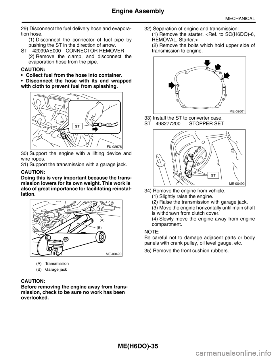
29) Disconnect the fuel delivery hose and evapora-
tion hose.
(1) Disconnect the connector of fuel pipe by
pushing the ST in the direction of arrow.
ST 42099AE000 CONNECTOR REMOVER
(2) Remove the clamp, and disconnect the
evaporation hose from the pipe.
CAUTION:
•Collect fuel from the hose into container.
•Disconnect the hose with its end wrapped
with cloth to prevent fuel from splashing.
30) Support the engine with a lifting device and
wire ropes.
31) Support the transmission with a garage jack.
CAUTION:
Doing this is very important because the trans-
mission lowers for its own weight. This work is
also of great importance for facilitating reinstal-
lation.
CAUTION:
Before removing the engine away from trans-
mission, check to be sure no work has been
overlooked.
32) Separation of engine and transmission:
(1) Remove the starter.
REMOVAL, Starter.>
(2) Remove the bolts which hold upper side of
transmission to engine.
33) Install the ST to converter case.
ST 498277200 STOPPER SET
34) Remove the engine from vehicle.
(1) Slightly raise the engine.
(2) Raise the transmission with garage jack.
(3) Move the engine horizontally until main shaft
is withdrawn from clutch cover.
(4) Slowly move the engine away from engine
compartment.
NOTE:
Be careful not to damage adjacent parts or body
panels with crank pulley, oil level gauge, etc.
35) Remove the front cushion rubbers.
(A) Transmission
(B) Garage jack
(A)
(B)
ME-00490
ME-02661
ST
ME-00492
Page 1904 of 2453
ME(H6DO)-38
Engine Assembly
MECHANICAL
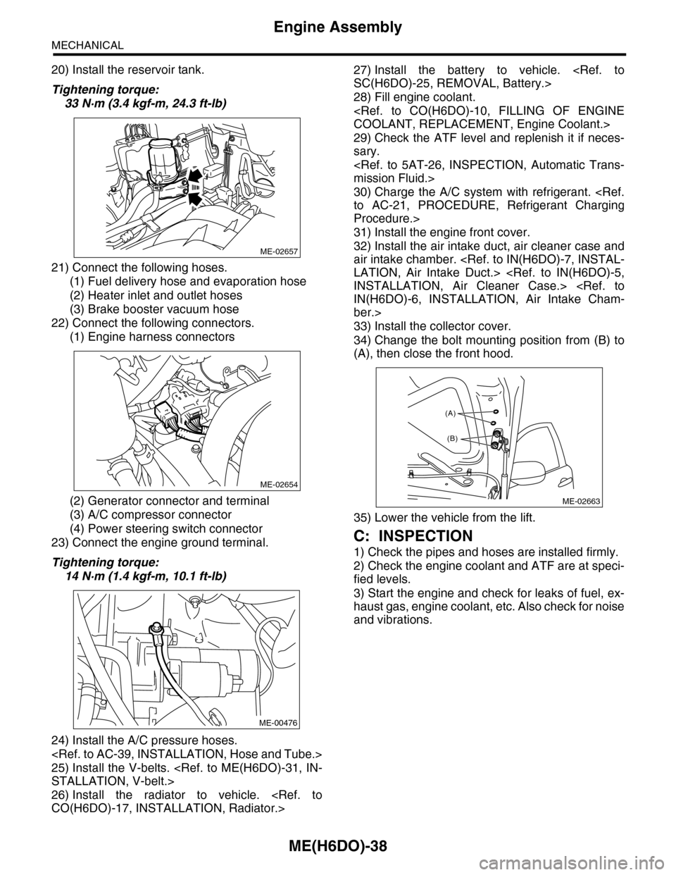
20) Install the reservoir tank.
Tightening torque:
33 N·m (3.4 kgf-m, 24.3 ft-lb)
21) Connect the following hoses.
(1) Fuel delivery hose and evaporation hose
(2) Heater inlet and outlet hoses
(3) Brake booster vacuum hose
22) Connect the following connectors.
(1) Engine harness connectors
(2) Generator connector and terminal
(3) A/C compressor connector
(4) Power steering switch connector
23) Connect the engine ground terminal.
Tightening torque:
14 N·m (1.4 kgf-m, 10.1 ft-lb)
24) Install the A/C pressure hoses.
25) Install the V-belts.
STALLATION, V-belt.>
26) Install the radiator to vehicle.
CO(H6DO)-17, INSTALLATION, Radiator.>
27) Install the battery to vehicle.
SC(H6DO)-25, REMOVAL, Battery.>
28) Fill engine coolant.
COOLANT, REPLACEMENT, Engine Coolant.>
29) Check the ATF level and replenish it if neces-
sary.
mission Fluid.>
30) Charge the A/C system with refrigerant.
to AC-21, PROCEDURE, Refrigerant Charging
Procedure.>
31) Install the engine front cover.
32) Install the air intake duct, air cleaner case and
air intake chamber.
LATION, Air Intake Duct.>
INSTALLATION, Air Cleaner Case.>
IN(H6DO)-6, INSTALLATION, Air Intake Cham-
ber.>
33) Install the collector cover.
34) Change the bolt mounting position from (B) to
(A), then close the front hood.
35) Lower the vehicle from the lift.
C: INSPECTION
1) Check the pipes and hoses are installed firmly.
2) Check the engine coolant and ATF are at speci-
fied levels.
3) Start the engine and check for leaks of fuel, ex-
haust gas, engine coolant, etc. Also check for noise
and vibrations.
ME-02657
ME-02654
ME-00476
ME-02663
(A)
(B)
Page 1944 of 2453
ME(H6DO)-78
Oil Switching Solenoid Valve
MECHANICAL
23.Oil Switching Solenoid Valve
A: REMOVAL
1) Disconnect the ground cable from battery.
2) Remove the air intake chamber.
ber.>
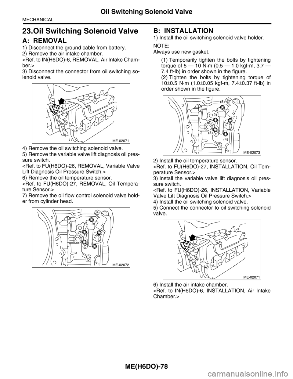
3) Disconnect the connector from oil switching so-
lenoid valve.
4) Remove the oil switching solenoid valve.
5) Remove the variable valve lift diagnosis oil pres-
sure switch.
Lift Diagnosis Oil Pressure Switch.>
6) Remove the oil temperature sensor.
ture Sensor.>
7) Remove the oil flow control solenoid valve hold-
er from cylinder head.
B: INSTALLATION
1) Install the oil switching solenoid valve holder.
NOTE:
Always use new gasket.
(1) Temporarily tighten the bolts by tightening
torque of 5 — 10 N·m (0.5 — 1.0 kgf-m, 3.7 —
7.4 ft-lb) in order shown in the figure.
(2) Tighten the bolts by tightening torque of
10±0.5 N·m (1.0±0.05 kgf-m, 7.4±0.37 ft-lb) in
order shown in the figure.
2) Install the oil temperature sensor.
perature Sensor.>
3) Install the variable valve lift diagnosis oil pres-
sure switch.
Valve Lift Diagnosis Oil Pressure Switch.>
4) Install the oil switching solenoid valve.
5) Connect the connector to oil switching solenoid
valve.
6) Install the air intake chamber.
Chamber.>
ME-02071
ME-02072
ME-02073
(2)(1)
(5)
(4)
(3)
ME-02071
Page 1956 of 2453
ME(H6DO)-90
Engine Noise
MECHANICAL
29.Engine Noise
A: INSPECTION
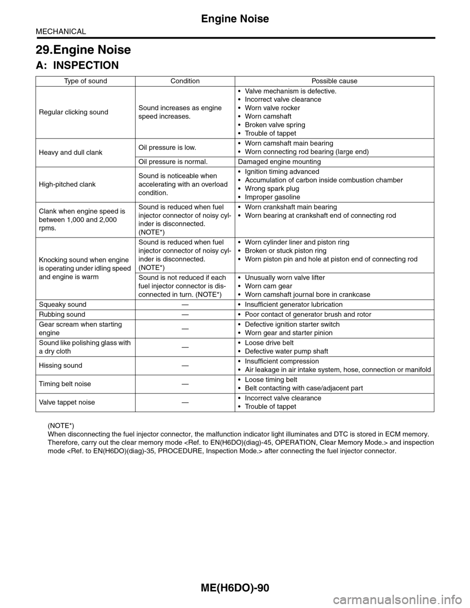
(NOTE*)
When disconnecting the fuel injector connector, the malfunction indicator light illuminates and DTC is stored in ECM memory.
Therefore, carry out the clear memory mode and inspection
mode after connecting the fuel injector connector.
Ty p e o f s o u n d C o n d i t i o n P o s s i b l e c a u s e
Regular clicking soundSound increases as engine
speed increases.
•Valve mechanism is defective.
•Incorrect valve clearance
•Worn valve rocker
•Worn camshaft
•Broken valve spring
•Trouble of tappet
Heavy and dull clankOil pressure is low.•Worn camshaft main bearing
•Worn connecting rod bearing (large end)
Oil pressure is normal. Damaged engine mounting
High-pitched clank
Sound is noticeable when
accelerating with an overload
condition.
•Ignition timing advanced
•Accumulation of carbon inside combustion chamber
•Wrong spark plug
•Improper gasoline
Clank when engine speed is
between 1,000 and 2,000
rpms.
Sound is reduced when fuel
injector connector of noisy cyl-
inder is disconnected.
(NOTE*)
•Worn crankshaft main bearing
•Worn bearing at crankshaft end of connecting rod
Knocking sound when engine
is operating under idling speed
and engine is warm
Sound is reduced when fuel
injector connector of noisy cyl-
inder is disconnected.
(NOTE*)
•Worn cylinder liner and piston ring
•Broken or stuck piston ring
•Worn piston pin and hole at piston end of connecting rod
Sound is not reduced if each
fuel injector connector is dis-
connected in turn. (NOTE*)
•Unusually worn valve lifter
•Worn cam gear
•Worn camshaft journal bore in crankcase
Squeaky sound — • Insufficient generator lubrication
Rubbing sound — • Poor contact of generator brush and rotor
Gear scream when starting
engine—•Defective ignition starter switch
•Worn gear and starter pinion
Sound like polishing glass with
a dry cloth—•Loose drive belt
•Defective water pump shaft
Hissing sound —•Insufficient compression
•Air leakage in air intake system, hose, connection or manifold
Timing belt noise —•Loose timing belt
•Belt contacting with case/adjacent part
Va l ve t a p p e t n o i s e —•Incorrect valve clearance
•Trouble of tappet
Page 1957 of 2453
SP(H6DO)-2
General Description
SPEED CONTROL SYSTEMS
1. General Description
A: SPECIFICATION
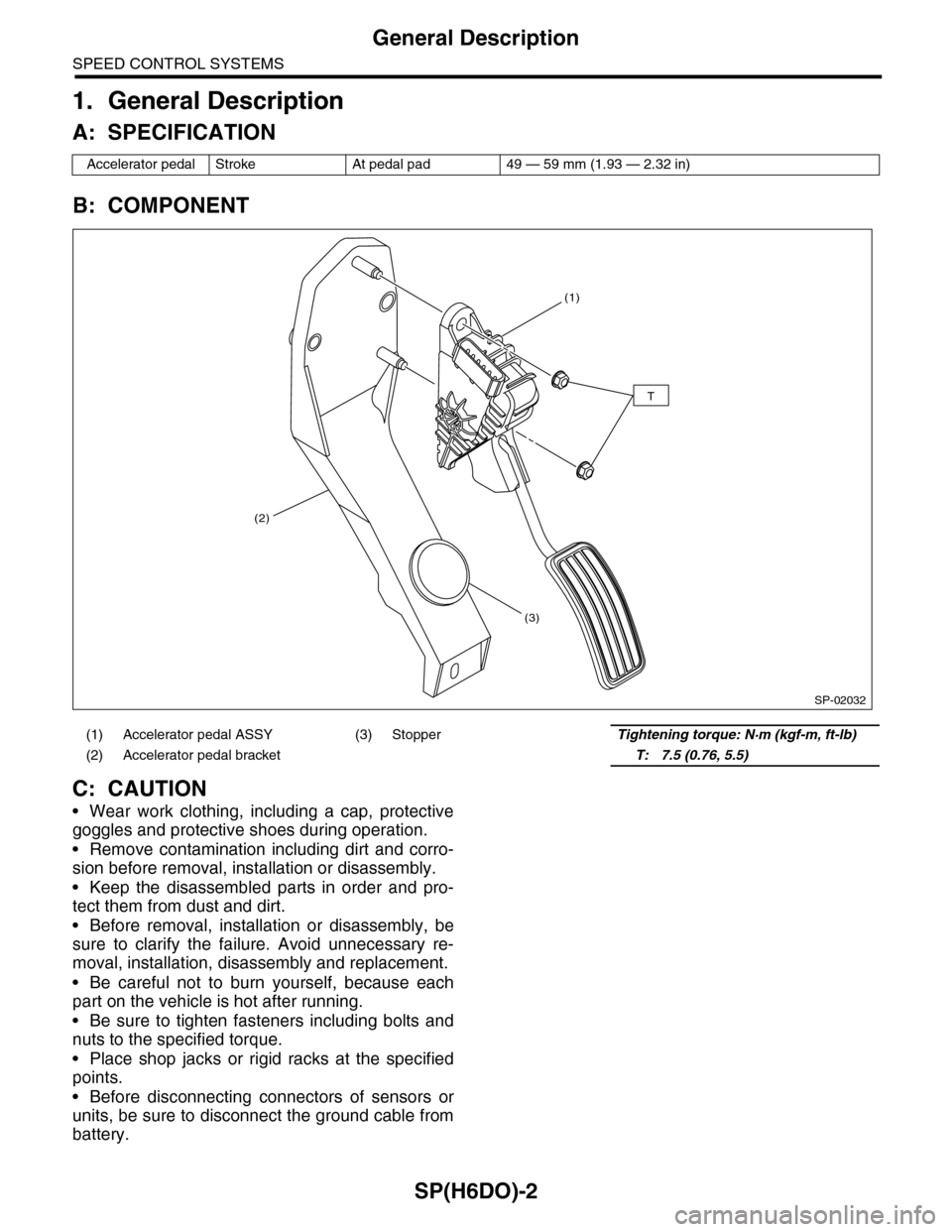
B: COMPONENT
C: CAUTION
•Wear work clothing, including a cap, protective
goggles and protective shoes during operation.
•Remove contamination including dirt and corro-
sion before removal, installation or disassembly.
•Keep the disassembled parts in order and pro-
tect them from dust and dirt.
•Before removal, installation or disassembly, be
sure to clarify the failure. Avoid unnecessary re-
moval, installation, disassembly and replacement.
•Be careful not to burn yourself, because each
part on the vehicle is hot after running.
•Be sure to tighten fasteners including bolts and
nuts to the specified torque.
•Place shop jacks or rigid racks at the specified
points.
•Before disconnecting connectors of sensors or
units, be sure to disconnect the ground cable from
battery.
Accelerator pedal Stroke At pedal pad 49 — 59 mm (1.93 — 2.32 in)
(1) Accelerator pedal ASSY (3) StopperTightening torque: N·m (kgf-m, ft-lb)
(2) Accelerator pedal bracket T: 7.5 (0.76, 5.5)
SP-02032
(1)
(2)
(3)
T