2009 SUBARU TRIBECA connector
[x] Cancel search: connectorPage 2069 of 2453
5AT-53
Control Valve Body
AUTOMATIC TRANSMISSION
17.Control Valve Body
A: REMOVAL
1) Set the vehicle on a lift.
2) Disconnect the ground cable from battery.
3) Lift-up the vehicle.
4) Clean the transmission exterior.
5) Remove the ATF drain plug to drain ATF.
CAUTION:
Immediately after the vehicle has been running
or after idling for a long time, the ATF will be
hot. Be careful not to burn yourself.
6) Tighten the ATF drain plug.
NOTE:
Use a new gasket.
Tightening torque:
20 N·m (2.0 kgf-m, 14.8 ft-lb)
7) Remove the oil pan.
CAUTION:
Be sure to prevent the entering of dust and oth-
er foreign matters into oil pan.
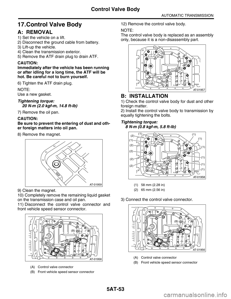
8) Remove the magnet.
9) Clean the magnet.
10) Completely remove the remaining liquid gasket
on the transmission case and oil pan.
11) Disconnect the control valve connector and
front vehicle speed sensor connector.
12) Remove the control valve body.
NOTE:
The control valve body is replaced as an assembly
only, because it is a non-disassembly part.
B: INSTALLATION
1) Check the control valve body for dust and other
foreign matter.
2) Install the control valve body to transmission by
equally tightening the bolts.
Tightening torque:
8 N·m (0.8 kgf-m, 5.8 ft-lb)
3) Connect the control valve connector.
(A) Control valve connector
(B) Front vehicle speed sensor connector
AT-01959
AT-01956
(B)
(A)
(1) 58 mm (2.28 in)
(2) 65 mm (2.56 in)
(A) Control valve connector
(B) Front vehicle speed sensor connector
AT-01957
AT-01958
(1)(1)
(1)
(2)
(2)
(2)
(2)
(1)
(1)
(1)
(1)
(1)
(2)
AT-01956
(B)
(A)
Page 2072 of 2453
5AT-56
Transmission Control Module (TCM)
AUTOMATIC TRANSMISSION
19.Transmission Control Mod-
ule (TCM)
A: REMOVAL
1) Disconnect the ground cable from battery.
2) Remove the lower cover and then disconnect
the connector.
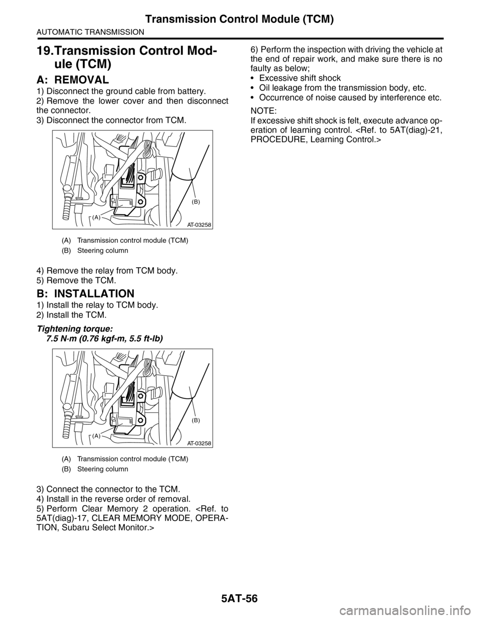
3) Disconnect the connector from TCM.
4) Remove the relay from TCM body.
5) Remove the TCM.
B: INSTALLATION
1) Install the relay to TCM body.
2) Install the TCM.
Tightening torque:
7.5 N·m (0.76 kgf-m, 5.5 ft-lb)
3) Connect the connector to the TCM.
4) Install in the reverse order of removal.
5) Perform Clear Memory 2 operation.
TION, Subaru Select Monitor.>
6) Perform the inspection with driving the vehicle at
the end of repair work, and make sure there is no
faulty as below;
•Excessive shift shock
•Oil leakage from the transmission body, etc.
•Occurrence of noise caused by interference etc.
NOTE:
If excessive shift shock is felt, execute advance op-
eration of learning control.
(A) Transmission control module (TCM)
(B) Steering column
(A) Transmission control module (TCM)
(B) Steering column
AT-03258(A)
(B)
AT-03258(A)
(B)
Page 2091 of 2453
5AT-75
Converter Case
AUTOMATIC TRANSMISSION
30.Converter Case
A: REMOVAL
1) Remove the transmission assembly from vehicle
body.
2) Remove the torque converter assembly.
3) Remove the transmission harness connector
from stay.
4) Remove the turbine speed sensor 1.
5) Remove the oil charge pipe.
6) Remove the ATF filter inlet and outlet pipes.
7) Remove the converter case attachment bolts.
8) Lay along the transmission body, and then re-
move the oil pan.
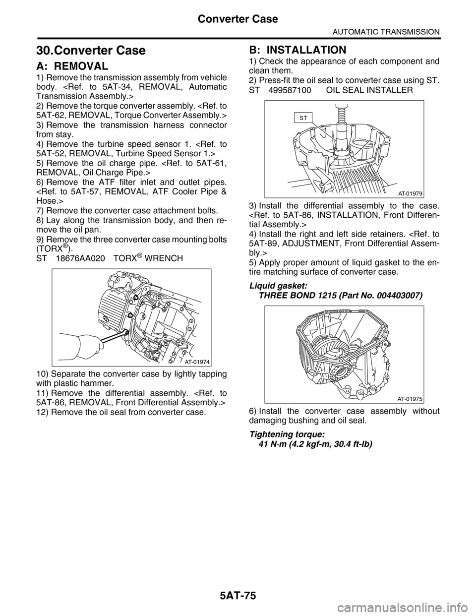
9) Remove the three converter case mounting bolts
(TORX®).
ST 18676AA020 TORX® WRENCH
10) Separate the converter case by lightly tapping
with plastic hammer.
11) Remove the differential assembly.
12) Remove the oil seal from converter case.
B: INSTALLATION
1) Check the appearance of each component and
clean them.
2) Press-fit the oil seal to converter case using ST.
ST 499587100 OIL SEAL INSTALLER
3) Install the differential assembly to the case.
4) Install the right and left side retainers.
bly.>
5) Apply proper amount of liquid gasket to the en-
tire matching surface of converter case.
Liquid gasket:
THREE BOND 1215 (Part No. 004403007)
6) Install the converter case assembly without
damaging bushing and oil seal.
Tightening torque:
41 N·m (4.2 kgf-m, 30.4 ft-lb)
AT-01974
AT-01979
ST
AT-01975
Page 2092 of 2453
5AT-76
Converter Case
AUTOMATIC TRANSMISSION
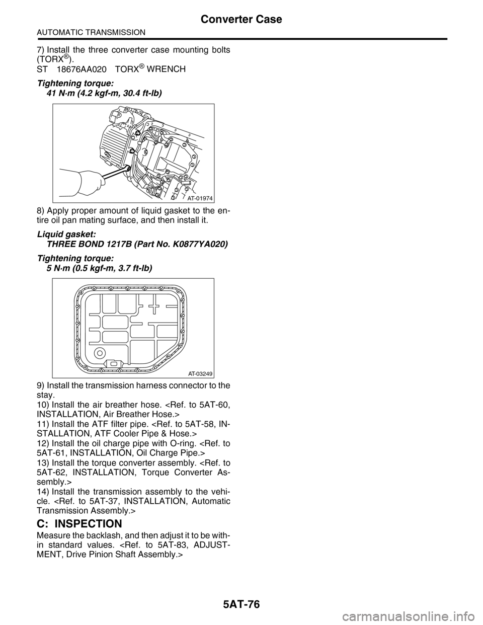
7) Install the three converter case mounting bolts
(TORX®).
ST 18676AA020 TORX® WRENCH
Tightening torque:
41 N·m (4.2 kgf-m, 30.4 ft-lb)
8) Apply proper amount of liquid gasket to the en-
tire oil pan mating surface, and then install it.
Liquid gasket:
THREE BOND 1217B (Part No. K0877YA020)
Tightening torque:
5 N·m (0.5 kgf-m, 3.7 ft-lb)
9) Install the transmission harness connector to the
stay.
10) Install the air breather hose.
11) Install the ATF filter pipe.
12) Install the oil charge pipe with O-ring.
13) Install the torque converter assembly.
sembly.>
14) Install the transmission assembly to the vehi-
cle.
C: INSPECTION
Measure the backlash, and then adjust it to be with-
in standard values.
AT-01974
AT-03249
Page 2093 of 2453
5AT-77
Oil Pump Cover
AUTOMATIC TRANSMISSION
31.Oil Pump Cover
A: REMOVAL
1) Remove the transmission assembly from vehicle
body.
2) Pull out the torque converter assembly.
3) Remove the transmission harness connector
from stay.
4) Remove the oil charge pipe.
5) Remove the ATF filter inlet and outlet pipes.
6) Separate the converter case and transmission
case.
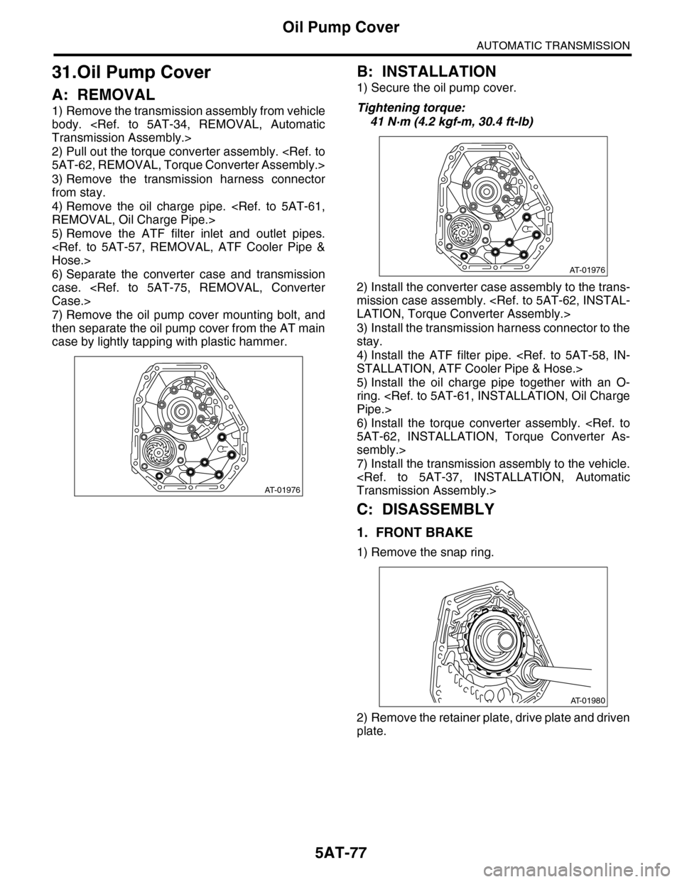
7) Remove the oil pump cover mounting bolt, and
then separate the oil pump cover from the AT main
case by lightly tapping with plastic hammer.
B: INSTALLATION
1) Secure the oil pump cover.
Tightening torque:
41 N·m (4.2 kgf-m, 30.4 ft-lb)
2) Install the converter case assembly to the trans-
mission case assembly.
3) Install the transmission harness connector to the
stay.
4) Install the ATF filter pipe.
5) Install the oil charge pipe together with an O-
ring.
6) Install the torque converter assembly.
sembly.>
7) Install the transmission assembly to the vehicle.
C: DISASSEMBLY
1. FRONT BRAKE
1) Remove the snap ring.
2) Remove the retainer plate, drive plate and driven
plate.
AT-01976
AT-01976
AT-01980
Page 2097 of 2453
5AT-81
Drive Pinion Shaft Assembly
AUTOMATIC TRANSMISSION
32.Drive Pinion Shaft Assembly
A: REMOVAL
1) Remove the transmission assembly from vehicle
body.
2) Pull out the torque converter assembly.
3) Remove the transmission harness connector
from stay.
4) Disconnect the air breather hose.
5) Remove the oil charge pipe.
6) Remove the ATF filter inlet and outlet pipes.
7) Separate the converter case and transmission
case.
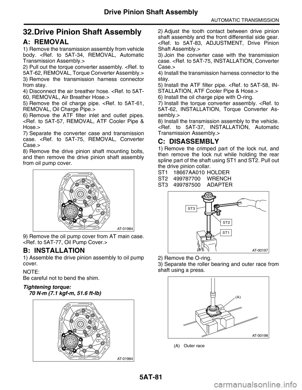
8) Remove the drive pinion shaft mounting bolts,
and then remove the drive pinion shaft assembly
from oil pump cover.
9) Remove the oil pump cover from AT main case.
B: INSTALLATION
1) Assemble the drive pinion assembly to oil pump
cover.
NOTE:
Be careful not to bend the shim.
Tightening torque:
70 N·m (7.1 kgf-m, 51.6 ft-lb)
2) Adjust the tooth contact between drive pinion
shaft assembly and the front differential side gear.
3) Join the converter case with the transmission
case.
4) Install the transmission harness connector to the
stay.
5) Install the ATF filter pipe.
6) Install the oil charge pipe with O-ring.
7) Install the torque converter assembly.
sembly.>
8) Install the transmission assembly to the vehicle.
C: DISASSEMBLY
1) Remove the crimped part of the lock nut, and
then remove the lock nut while holding the rear
spline part of the shaft using ST1 and ST2. Pull out
the drive pinion collar.
ST1 18667AA010 HOLDER
ST2 499787700 WRENCH
ST3 499787500 ADAPTER
2) Remove the O-ring.
3) Separate the roller bearing and outer race from
shaft using a press.
AT-01984
AT-01984
(A) Outer race
AT-00197
ST1
ST3
ST2
AT-00198
(A)
Page 2102 of 2453

5AT-86
Front Differential Assembly
AUTOMATIC TRANSMISSION
33.Front Differential Assembly
A: REMOVAL
1) Remove the transmission assembly from vehicle
body.
2) Pull out the torque converter assembly.
3) Remove the transmission harness connector
from stay.
4) Remove the oil charge pipe.
5) Remove the ATF filter inlet and outlet pipes.
6) Separate the converter case from the transmis-
sion case.
7) Remove the differential side retainers using ST.
NOTE:
Hold the differential case assembly by hand to
avoid damaging the retainer mounting hole of the
converter case.
ST 18630AA010 WRENCH COMPL RETAIN-
ER
8) Remove the differential assembly while being
careful not to damage the attachment part of retain-
er.
B: INSTALLATION
1) When installing the differential assembly to
case, be careful not to damage the inside of case
(particularly, the differential side retainer mating
surface).
2) Install the O-ring to left and right side retainer.
3) Using the ST, install the side retainer.
ST 18630AA010 WRENCH COMPL RETAIN-
ER
4) Adjust the backlash of the front differential.
sembly.>
5) Install the lock plate.
Tightening torque:
25 N·m (2.5 kgf-m, 18 ft-lb)
6) Install the converter case to the transmission
case.
7) Install the transmission harness connector to the
stay.
8) Install the ATF filter pipe.
9) Install the oil charge pipe together with an O-
ring.
10) Install the torque converter assembly.
sembly.>
11) Install the transmission assembly to the vehi-
cle.
C: DISASSEMBLY
1. DIFFERENTIAL CASE ASSEMBLY
1) Remove the taper roller bearing using the ST
and a press.
ST 498077000 REMOVER
(A) Differential ASSY
AT-01987
(A)
(A) Lock plate
AT-01988
(A)
AT-00216
Page 2107 of 2453
5AT-91
AT Main Case
AUTOMATIC TRANSMISSION
34.AT Main Case
A: REMOVAL
1) Remove the transmission assembly from vehicle
body.
2) Pull out the torque converter assembly.
3) Remove the transmission harness connector
from stay.
4) Disconnect the air breather hose.
5) Remove the oil charge pipe.
6) Remove the ATF filter inlet and outlet pipes.
7) Remove the extension case.
8) Remove the center differential carrier.
9) Remove the reduction driven gear.
10) Separate the converter case from the transmis-
sion case.
11) Remove the control valve body.
12) Remove the oil pump cover.
NOTE:
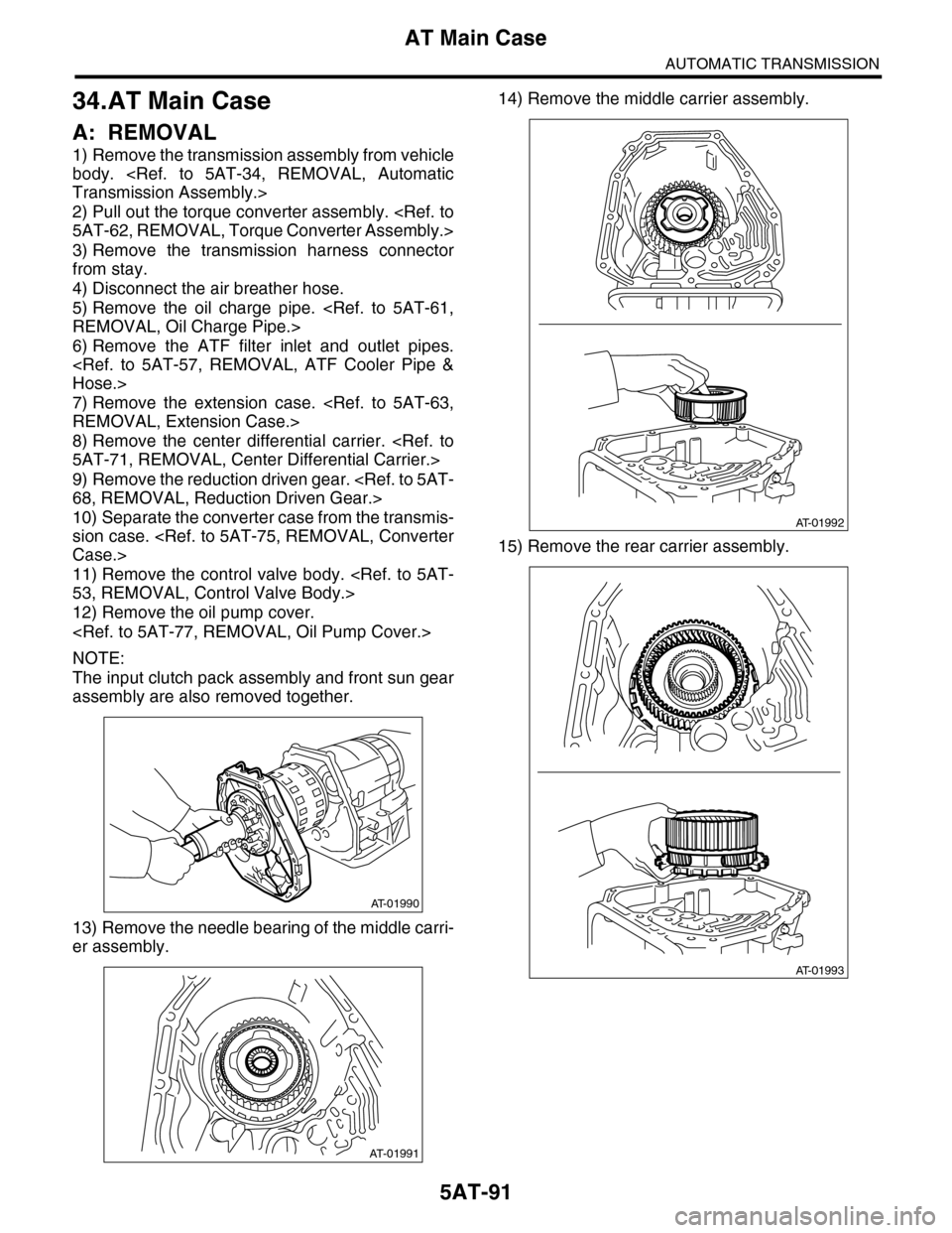
The input clutch pack assembly and front sun gear
assembly are also removed together.
13) Remove the needle bearing of the middle carri-
er assembly.
14) Remove the middle carrier assembly.
15) Remove the rear carrier assembly.
AT-01990
AT-01991
AT-01992
AT-01993