Page 1958 of 2453
SP(H6DO)-3
Accelerator Pedal
SPEED CONTROL SYSTEMS
2. Accelerator Pedal
A: REMOVAL
1) Disconnect the ground cable from battery.
2) Disconnect the connector.
3) Remove the nut securing accelerator pedal as-
sembly.
B: INSTALLATION
Install in the reverse order of removal.
Tightening torque:
7.5 N·m (0.76 kgf-m, 5.5 ft-lb)
C: DISASSEMBLY
NOTE:
The accelerator pedal cannot be disassembled.
SP-02035
Page 1963 of 2453
SC(H6DO)-5
General Description
STARTING/CHARGING SYSTEMS
C: CAUTION
•Wear work clothing, including a cap, protective
goggles and protective shoes during operation.
•Remove contamination including dirt and corro-
sion before removal, installation or disassembly.
•Keep the disassembled parts in order and pro-
tect them from dust and dirt.
•Before removal, installation or disassembly, be
sure to clarify the failure. Avoid unnecessary re-
moval, installation, disassembly and replacement.
•Be careful not to burn yourself, because each
part on the vehicle is hot after running.
•Be sure to tighten fasteners including bolts and
nuts to the specified torque.
•Place shop jacks or rigid racks at the specified
points.
•Before disconnecting connectors of sensors or
units, be sure to disconnect the ground cable from
battery.
Page 1964 of 2453

SC(H6DO)-6
Starter
STARTING/CHARGING SYSTEMS
2. Starter
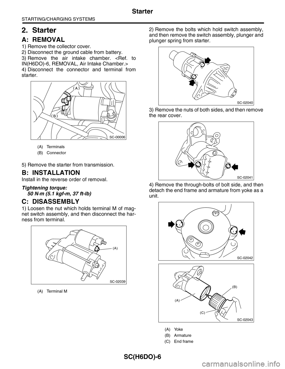
A: REMOVAL
1) Remove the collector cover.
2) Disconnect the ground cable from battery.
3) Remove the air intake chamber.
IN(H6DO)-6, REMOVAL, Air Intake Chamber.>
4) Disconnect the connector and terminal from
starter.
5) Remove the starter from transmission.
B: INSTALLATION
Install in the reverse order of removal.
Tightening torque:
50 N·m (5.1 kgf-m, 37 ft-lb)
C: DISASSEMBLY
1) Loosen the nut which holds terminal M of mag-
net switch assembly, and then disconnect the har-
ness from terminal.
2) Remove the bolts which hold switch assembly,
and then remove the switch assembly, plunger and
plunger spring from starter.
3) Remove the nuts of both sides, and then remove
the rear cover.
4) Remove the through-bolts of bolt side, and then
detach the end frame and armature from yoke as a
unit.
(A) Terminals
(B) Connector
(A) Terminal M
SC-00006
(A)
SC-02039
(A) Yoke
(B) Armature
(C) End frame
SC-02040
SC-02041
SC-02042
SC-02043
(A)
(C)
(B)
Page 1977 of 2453
SC(H6DO)-19
Generator
STARTING/CHARGING SYSTEMS
3. Generator
A: REMOVAL
1) Remove the collector cover.
2) Disconnect the ground cable from battery.
3) Disconnect the connector and terminal from
generator.
4) Remove the V-belts.
REMOVAL, V-belt.>
5) Remove the bolts which install the generator
onto bracket.
B: INSTALLATION
Install in the reverse order of removal.
Tightening torque:
25 N·m (2.5 kgf-m, 18.1 ft-lb)
CAUTION:
Check and adjust the V-belt tension.
C: DISASSEMBLY
1) Remove the four through-bolts.
2) Heat the portion (A) of rear cover to 50°C
(122°F) with a heater drier.
3) Then insert the tip of a flat tip screwdriver into the
gap between stator core and front cover. Pry them
apart to disassemble.
4) Hold the rotor with a vise and remove pulley nut.
SC-02003
SC-02098
SC-02098
(A) Screwdriver
SC-00078
SC-00079
(A)
SC-00080
(A)
(A)
SC-00035
Page 1992 of 2453
PM-9
Spark Plug
PERIODIC MAINTENANCE SERVICES
5. Spark Plug
A: REPLACEMENT
1) Remove the battery and battery carrier.
2) Remove the air cleaner case.
3) Detach the connector from ignition coil.
4) Remove the ignition coil.
5) Remove the spark plug with a spark plug socket.
6) Tighten the new spark plug lightly with hand, and
then secure with a spark plug socket to the speci-
fied torque.
Recommended spark plug:
NGK: ILFR6B
Tightening torque:
21 N·m (2.1 kgf-m, 15.2 ft-lb)
7) Tighten the ignition coil.
Tightening torque:
16 N·m (1.6 kgf-m, 11.7 ft-lb)
NOTE:
•Be sure to place the gasket between the cylinder
head and spark plug.
•If the torque wrench is not available, tighten the
spark plug until gasket contacts cylinder head; then
tighten further 1/4 to 1/2 turns.
(A) Bracket
(B) Connector
IG-02004(B)
(A)
PM-00112
Page 2015 of 2453
PM-32
Supplemental Restraint System
PERIODIC MAINTENANCE SERVICES
22.Supplemental Restraint System
A: INSPECTION
Check the airbag system in accordance with the result of the self-diagnosis.
agnostic Procedure.>
1) Make sure that airbag connectors are connected. If not, properly connect. When the ignition switch is
turned ON with the connector(s) disconnected, the airbag warning light blinks to identify the fault.
2) Connect the Subaru Select Monitor to data link connector. Turn the ignition switch to ON, and Subaru Se-
lect Monitor switch to ON.
3) Read the Diagnostic Trouble Code (DTC) using Subaru Select Monitor.
AGNOSTIC TROUBLE CODE (DTC), OPERATION, Subaru Select Monitor.>
4) Inspect the airbag system according to the Diagnostic Trouble Code (DTC).
PM-00298
Page 2048 of 2453

5AT-32
Line Pressure Test
AUTOMATIC TRANSMISSION
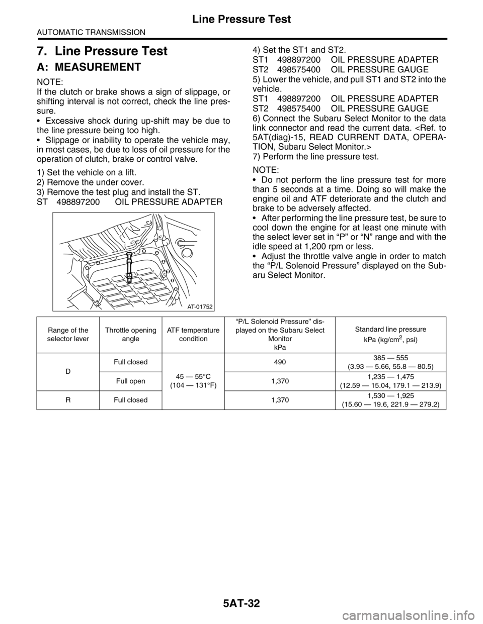
7. Line Pressure Test
A: MEASUREMENT
NOTE:
If the clutch or brake shows a sign of slippage, or
shifting interval is not correct, check the line pres-
sure.
•Excessive shock during up-shift may be due to
the line pressure being too high.
•Slippage or inability to operate the vehicle may,
in most cases, be due to loss of oil pressure for the
operation of clutch, brake or control valve.
1) Set the vehicle on a lift.
2) Remove the under cover.
3) Remove the test plug and install the ST.
ST 498897200 OIL PRESSURE ADAPTER
4) Set the ST1 and ST2.
ST1 498897200 OIL PRESSURE ADAPTER
ST2 498575400 OIL PRESSURE GAUGE
5) Lower the vehicle, and pull ST1 and ST2 into the
vehicle.
ST1 498897200 OIL PRESSURE ADAPTER
ST2 498575400 OIL PRESSURE GAUGE
6) Connect the Subaru Select Monitor to the data
link connector and read the current data.
5AT(diag)-15, READ CURRENT DATA, OPERA-
TION, Subaru Select Monitor.>
7) Perform the line pressure test.
NOTE:
•Do not perform the line pressure test for more
than 5 seconds at a time. Doing so will make the
engine oil and ATF deteriorate and the clutch and
brake to be adversely affected.
•After performing the line pressure test, be sure to
cool down the engine for at least one minute with
the select lever set in “P” or “N” range and with the
idle speed at 1,200 rpm or less.
•Adjust the throttle valve angle in order to match
the “P/L Solenoid Pressure” displayed on the Sub-
aru Select Monitor.
AT-01752
Range of the
selector lever
Throttle opening
angle
AT F t e m p e r a t u r e
condition
“P/L Solenoid Pressure” dis-
played on the Subaru Select
Monitor
kPa
Standard line pressure
kPa (kg/cm2, psi)
D
Full closed
45 — 55°C
(104 — 131°F)
490385 — 555
(3.93 — 5.66, 55.8 — 80.5)
Full open 1,3701,235 — 1,475
(12.59 — 15.04, 179.1 — 213.9)
RFull closed 1,3701,530 — 1,925
(15.60 — 19.6, 221.9 — 279.2)
Page 2049 of 2453

5AT-33
Transfer Clutch Pressure Test
AUTOMATIC TRANSMISSION
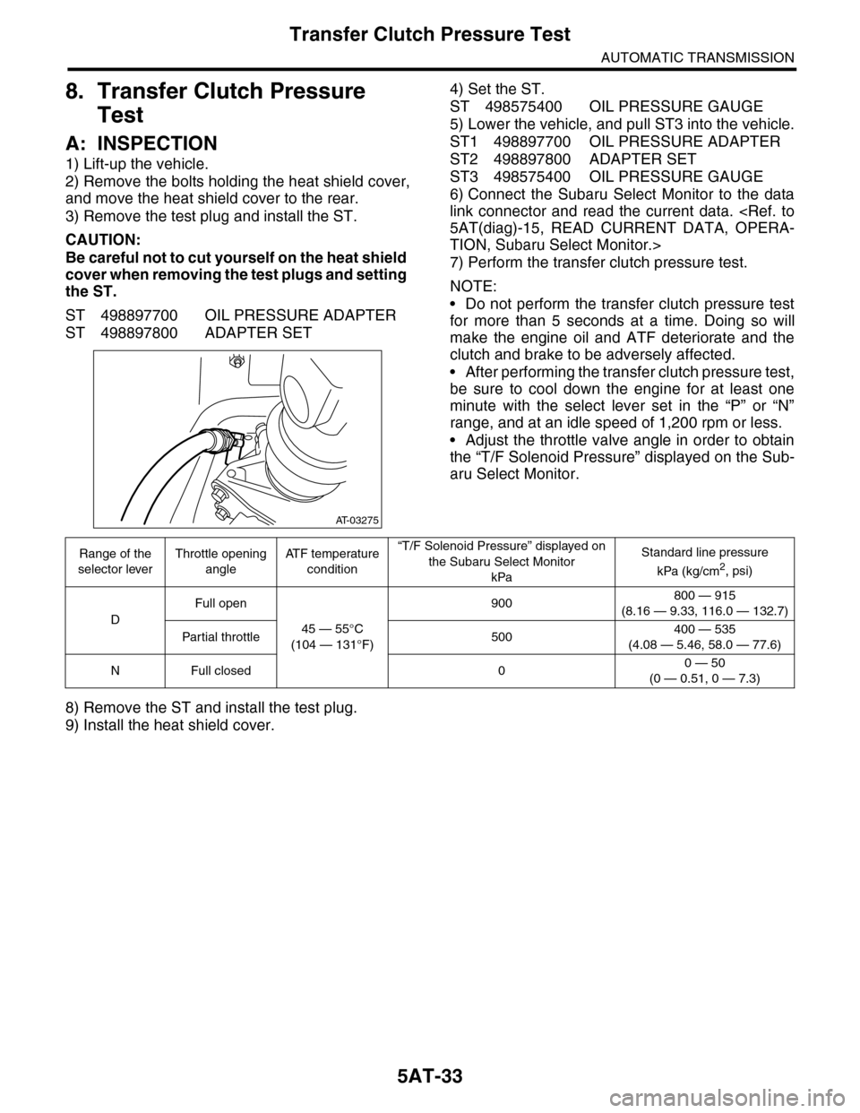
8. Transfer Clutch Pressure
Test
A: INSPECTION
1) Lift-up the vehicle.
2) Remove the bolts holding the heat shield cover,
and move the heat shield cover to the rear.
3) Remove the test plug and install the ST.
CAUTION:
Be careful not to cut yourself on the heat shield
cover when removing the test plugs and setting
the ST.
ST 498897700 OIL PRESSURE ADAPTER
ST 498897800 ADAPTER SET
4) Set the ST.
ST 498575400 OIL PRESSURE GAUGE
5) Lower the vehicle, and pull ST3 into the vehicle.
ST1 498897700 OIL PRESSURE ADAPTER
ST2 498897800 ADAPTER SET
ST3 498575400 OIL PRESSURE GAUGE
6) Connect the Subaru Select Monitor to the data
link connector and read the current data.
5AT(diag)-15, READ CURRENT DATA, OPERA-
TION, Subaru Select Monitor.>
7) Perform the transfer clutch pressure test.
NOTE:
•Do not perform the transfer clutch pressure test
for more than 5 seconds at a time. Doing so will
make the engine oil and ATF deteriorate and the
clutch and brake to be adversely affected.
•After performing the transfer clutch pressure test,
be sure to cool down the engine for at least one
minute with the select lever set in the “P” or “N”
range, and at an idle speed of 1,200 rpm or less.
•Adjust the throttle valve angle in order to obtain
the “T/F Solenoid Pressure” displayed on the Sub-
aru Select Monitor.
8) Remove the ST and install the test plug.
9) Install the heat shield cover.
AT-03275
Range of the
selector lever
Throttle opening
angle
AT F t e m p e r a t u r e
condition
“T/F Solenoid Pressure” displayed on
the Subaru Select Monitor
kPa
Standard line pressure
kPa (kg/cm2, psi)
D
Full open
45 — 55°C
(104 — 131°F)
900800 — 915
(8.16 — 9.33, 116.0 — 132.7)
Par tial throttle 500400 — 535
(4.08 — 5.46, 58.0 — 77.6)
NFull closed 00 — 50
(0 — 0.51, 0 — 7.3)