Page 280 of 2453
EI-38
Console Box
EXTERIOR/INTERIOR TRIM
15.Console Box
A: REMOVAL
1) Remove the ring indicator (A) and console front
panel (B).
NOTE:
The ring indicator can be easily removed by insert-
ing the clip remover or equivalent into the positions
indicated by arrows.
2) Remove the screws.
3) Remove the bolts inside the upper pocket.
4) Pull out the console lower pocket, and remove
the console box.
B: INSTALLATION
Install in the reverse order of removal.
EI-01299
PRND
:(B)
(B)
(A)
EI-01300
PRND
EI-01324
Page 281 of 2453
EI-39
Center Console
EXTERIOR/INTERIOR TRIM
16.Center Console
A: REMOVAL
1) Remove the control panel.
MOVAL, Control Panel.>
2) Remove the instrument panel lower cover.
to EI-36, REMOVAL, Instrument Panel Lower Cov-
er.>
3) Remove the glove box.
AL, Glove Box.>
4) Remove the console box.
MOVAL, Console Box.>
5) Remove the screws and clips (A) to remove the
console side panel upper.
•Driver’s side
•Passenger’s side
B: INSTALLATION
Install in the reverse order of removal.
EI-01325:(A)
EI-01326:(A)
Page 284 of 2453

EI-42
Instrument Panel Assembly
EXTERIOR/INTERIOR TRIM
B: INSTALLATION
1. INSTRUMENT PANEL UPPER
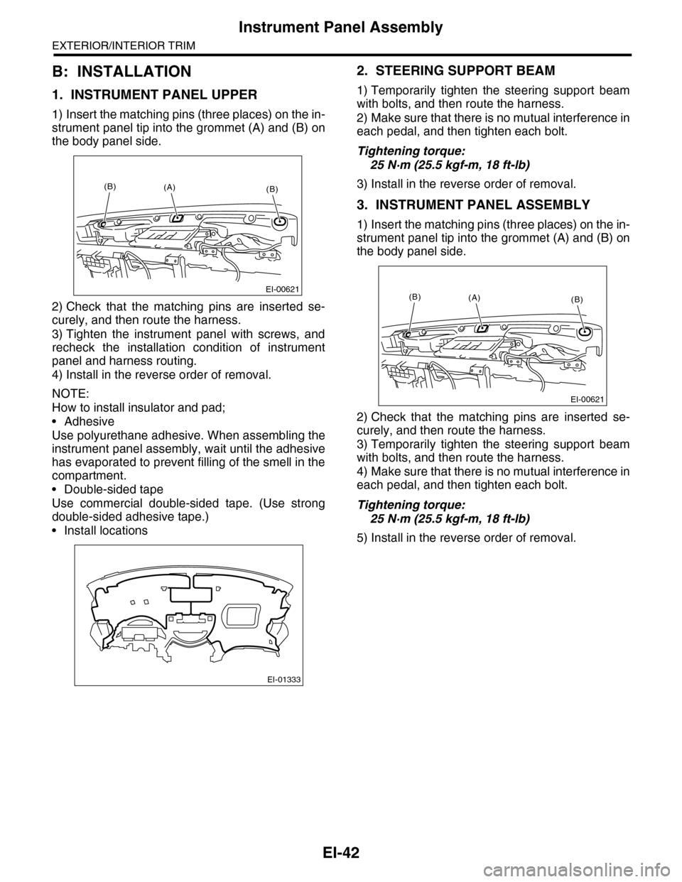
1) Insert the matching pins (three places) on the in-
strument panel tip into the grommet (A) and (B) on
the body panel side.
2) Check that the matching pins are inserted se-
curely, and then route the harness.
3) Tighten the instrument panel with screws, and
recheck the installation condition of instrument
panel and harness routing.
4) Install in the reverse order of removal.
NOTE:
How to install insulator and pad;
•Adhesive
Use polyurethane adhesive. When assembling the
instrument panel assembly, wait until the adhesive
has evaporated to prevent filling of the smell in the
compartment.
•Double-sided tape
Use commercial double-sided tape. (Use strong
double-sided adhesive tape.)
•Install locations
2. STEERING SUPPORT BEAM
1) Temporarily tighten the steering support beam
with bolts, and then route the harness.
2) Make sure that there is no mutual interference in
each pedal, and then tighten each bolt.
Tightening torque:
25 N·m (25.5 kgf-m, 18 ft-lb)
3) Install in the reverse order of removal.
3. INSTRUMENT PANEL ASSEMBLY
1) Insert the matching pins (three places) on the in-
strument panel tip into the grommet (A) and (B) on
the body panel side.
2) Check that the matching pins are inserted se-
curely, and then route the harness.
3) Temporarily tighten the steering support beam
with bolts, and then route the harness.
4) Make sure that there is no mutual interference in
each pedal, and then tighten each bolt.
Tightening torque:
25 N·m (25.5 kgf-m, 18 ft-lb)
5) Install in the reverse order of removal.
EI-00621
(B)(B)(A)
EI-01333
EI-00621
(B)(B)(A)
Page 286 of 2453

EI-44
Side Trim
EXTERIOR/INTERIOR TRIM
5. CENTER PILLAR LOWER TRIM
1) Remove the front door scuff plate.
2) Remove the rear door scuff plate.
3) Remove the clip, and remove the center pillar
lower trim.
6. CENTER PILLAR UPPER TRIM
1) When removing the parts of passenger’s side,
disconnect the ground cable from battery and wait
for at least 20 seconds before starting work.
2) Remove the front door scuff plate.
3) Remove the rear door scuff plate.
4) Remove the center pillar lower trim.
5) Turn over the floor mat to remove the seat belt
lower anchor bolt.
6) Disconnect the connector of belt tension sensor
on passenger’s side.
7) Remove the cap (A) on the upper side of pillar
trim, and remove the bolt inside.
8) Remove the clip, and remove the center pillar
upper trim.
B: INSTALLATION
Install each side trim in the reverse order of remov-
al.
NOTE:
When installing the side trim, make sure that the
clips and hooks match the holes of vehicle body be-
fore pushing the parts.
EI-01338
EI-01341
EI-01340
EI-01339
(A)
Page 288 of 2453
EI-46
Rear Quarter Trim
EXTERIOR/INTERIOR TRIM
13) Disconnect each connector, and remove the
rear quarter upper trim.
B: INSTALLATION
Install in the reverse order of removal.
EI-01350
(A)(A)
Page 289 of 2453

EI-47
Floor Mat
EXTERIOR/INTERIOR TRIM
20.Floor Mat
A: REMOVAL
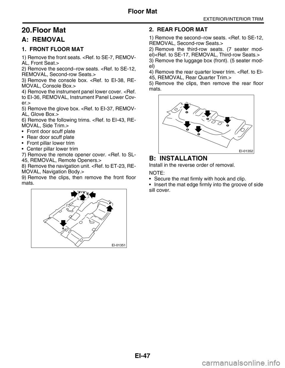
1. FRONT FLOOR MAT
1) Remove the front seats.
AL, Front Seat.>
2) Remove the second–row seats.
REMOVAL, Second-row Seats.>
3) Remove the console box.
MOVAL, Console Box.>
4) Remove the instrument panel lower cover.
to EI-36, REMOVAL, Instrument Panel Lower Cov-
er.>
5) Remove the glove box.
AL, Glove Box.>
6) Remove the following trims.
MOVAL, Side Trim.>
•Front door scuff plate
•Rear door scuff plate
•Front pillar lower trim
•Center pillar lower trim
7) Remove the remote opener cover.
45, REMOVAL, Remote Openers.>
8) Remove the navigation unit.
MOVAL, Navigation Body.>
9) Remove the clips, then remove the front floor
mats.
2. REAR FLOOR MAT
1) Remove the second–row seats.
REMOVAL, Second-row Seats.>
2) Remove the third-row seats. (7 seater mod-
el)
3) Remove the luggage box (front). (5 seater mod-
el)
4) Remove the rear quarter lower trim.
45, REMOVAL, Rear Quarter Trim.>
5) Remove the clips, then remove the rear floor
mats.
B: INSTALLATION
Install in the reverse order of removal.
NOTE:
•Secure the mat firmly with hook and clip.
•Insert the mat edge firmly into the groove of side
sill cover.
EI-01351
EI-01352
Page 290 of 2453
EI-48
Sun Visor
EXTERIOR/INTERIOR TRIM
21.Sun Visor
A: REMOVAL
1) Remove the cover, loosen the mounting screws,
and remove the sun visor.
2) Disconnect the connector. (Model with vanity
mirror light)
3) While pressing the (A) on the both side using flat
tip screwdriver, pull the sun visor hook to remove it.
B: INSTALLATION
Install in the reverse order of removal.
EI-00661
EI-00662
(A)
(A)
Page 291 of 2453
EI-49
Assist Grip
EXTERIOR/INTERIOR TRIM
22.Assist Grip
A: REMOVAL
1) Remove the screw cover, and remove the screw
inside.
2) Pull the left side of assist grip toward you, and ro-
tate the right side of it counterclockwise to remove.
3) Remove the roof trim.
AL, Roof Trim.>
4) Remove the bolts, and remove the assist grip
bracket.
B: INSTALLATION
Install in the reverse order of removal.
CAUTION:
Be sure to install the grommet to assist grip
bracket.
When the assist grip is installed with no grom-
met, it ill cause the grip to not return properly.
(A) Grommet
EI-00809
EI-01065
(A)