Page 264 of 2453
EI-22
Front Bumper
EXTERIOR/INTERIOR TRIM
2. FRONT BUMPER BEAM ASSEMBLY
1) Remove the front bumper face.
2) Remove the energy absorber foam from bumper
beam.
3) Remove the bolts, and remove the bumper
beam assembly from vehicle body.
NOTE:
After all bolts are removed, raise the whole bumper
beam a little to remove it from vehicle body.
B: INSTALLATION
1. FRONT BUMPER FACE
1) Mount the bumper face securely in the gap be-
tween guide bracket (A) and fender (B).
2) Install in the reverse order of removal.
2. FRONT BUMPER BEAM ASSEMBLY
Install in the reverse order of removal.
Tightening torque:
Refer to “COMPONENT” of “General Descrip-
tion”.
NENT, General Description.>
EI-01271
EI-01272
(A)
(B)
Page 269 of 2453

EI-27
Front Bumper
EXTERIOR/INTERIOR TRIM
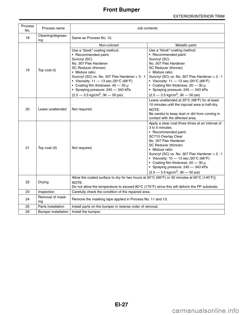
18Cleaning/degreas-
ingSame as Process No. 12.
19 Top coat (I)
Non-colored Metallic paint
Use a “block” coating method.
•Recommended paint:
Suncryl (SC)
No. 307 Flex Hardener
SC Reducer (thinner)
•Mixture ratio:
Suncryl (SC) vs. No. 307 Flex Hardener = 3 : 1
•Viscosity: 11 — 13 sec./20°C (68°F)
• Coating film thickness: 40 — 50 µ
•Spraying pressure: 245 — 343 kPa
(2.5 — 3.5 kg/cm2, 36 — 50 psi)
Use a “block” coating method.
•Recommended paint:
Suncryl (SC)
No. 307 Flex Hardener
SC Reducer (thinner)
•Mixture ratio:
Suncryl (SC) vs. No. 307 Flex Hardener = 3 : 1
•Viscosity: 11 — 13 sec./20°C (68°F)
•Coating film thickness: 20 — 30 µ
•Spraying pressure: 245 — 343 kPa
(2.5 — 3.5 kg/cm2, 36 — 50 psi)
20 Leave unattended Not required.
Leave unattended at 20°C (68°F) for at least
10 minutes until the topcoat area is half-dry.
NOTE:
Be careful to keep dust or dirt from coming in
contact with the affected area.
21 Top coat (II) Not required.
Apply a clear coat three times at an interval of
3 to 5 minutes.
•Recommended paint:
SC710 Overlay Clear
No. 307 Flex Hardener
SC Reducer (thinner)
•Mixture ratio:
Suncryl (SC) vs. No. 307 Flex Hardener = 3 : 1
•Viscosity: 10 — 13 sec./20°C (68°F)
•Coating film thickness: 20 — 30 µ
•Spraying pressure: 245 — 343 kPa
(2.5 — 3.5 kg/cm2, 36 — 50 psi)
22 Drying
Allow the coated surface to dry for two hours at 20°C (68°F) or 30 minutes at 60°C (140°F)].
NOTE:Do not allow the temperature to exceed 80°C (176°F) since this will deform the PP substrate.
23 Inspection Carefully check the condition of the repaired area.
24Removal of mask-
ingRemove the masking tape applied in Process No. 11 and 13.
25 Parts installation Install parts on the bumper in reverse order of removal.
26 Bumper installation Install the bumper.
Process
No.Process name Job contents
Page 271 of 2453
EI-29
Rear Bumper
EXTERIOR/INTERIOR TRIM
B: INSTALLATION
Install in the reverse order of removal.
Tightening torque:
Refer to “COMPONENT” of “General Descrip-
tion”.
General Description.>
C: REPAIR
Refer to front bumper repair.
PAIR, Front Bumper.>
Page 272 of 2453
EI-30
Cowl Panel
EXTERIOR/INTERIOR TRIM
8. Cowl Panel
A: REMOVAL
1) Remove the wiper arm.
MOVAL, Front Wiper Arm.>
2) Remove the weather strip clips, and remove the
weather strip.
NOTE:
If the weather strip clip is removed with excessive
force, the weather strip may be damaged. Be sure
to use a clip remover to remove.
3) Remove the clip and remove the cowl panel
side.
4) Pull and remove the cowl panel RH.
5) Remove the cowl panel LH.
B: INSTALLATION
Install in the reverse order of removal.
NOTE:
Hook the craw of cowl panel to the windshield.EI-01279
EB-00141
EI-01280
(A)
EI-01281
EI-01282
Page 273 of 2453
EI-31
Roof Spoiler
EXTERIOR/INTERIOR TRIM
9. Roof Spoiler
A: REMOVAL
1) Remove the rear gate upper trim.
REMOVAL, Rear Gate Trim.>
2) Disconnect the connector of high-mounted stop
light and the washer hose of rear washer.
3) Remove the nuts.
4) Remove the clips, and remove the roof spoiler.
B: INSTALLATION
Install in the reverse order of removal.
Tightening torque:
4.5 N·m (0.46 kgf-m, 3.32 ft-lb)
EI-01283
EI-01284
Page 277 of 2453
EI-35
Door Trim
EXTERIOR/INTERIOR TRIM
12.Door Trim
A: REMOVAL
1) Disconnect the ground cable from battery.
2) Remove the cover (A) at inner remote.
3) Remove the bottom cover at the pull handle.
4) Remove the screw to remove the power window
switch assembly.
•Front door
•Rear door
5) Remove the gusset cover.
•Front door
•Rear door
6) Remove the clip, and disconnect the each con-
nector to remove the door trim.
•Front door trim
•Rear door trim
B: INSTALLATION
Install in the reverse order of removal.
EI-01285
(A)
EI-01286
EI-01287
EI-01376
EI-01288
EI-01289
EI-01290
Page 278 of 2453
EI-36
Instrument Panel Lower Cover
EXTERIOR/INTERIOR TRIM
13. Instrument Panel Lower Cover
A: REMOVAL
1) Remove the front door scuff plate and front pillar
lower trim.
2) Remove the instrument panel side cover LH.
3) Remove the clips, and remove the console side
panel lower LH.
4) Remove the clips, and remove the instrument
panel lower cover under.
5) Remove the clips and hooks, disconnect the
connectors, and then remove the instrument panel
lower cover upper.
B: INSTALLATION
Install in the reverse order of removal.
(A) Hook
(A) Hook
EI-01291:(A)
EI-01292:(A)
EI-01293
EI-01294:(A)
Page 279 of 2453
EI-37
Glove Box
EXTERIOR/INTERIOR TRIM
14.Glove Box
A: REMOVAL
1) Remove the front door scuff plate and front pillar
lower trim.
2) Remove the instrument panel side cover RH.
3) Remove the console side panel lower RH.
4) Remove the clips, and remove the glove box
lower cover.
5) Remove the screws (A) and hooks (B), and dis-
connect the connector, and then remove the glove
box assembly.
6) Remove the clips (A), left and right stoppers of
glove box lid (B) and damper strap, and then re-
move the glove box lid.
NOTE:
The glove box lid can be removed without using the
glove box assembly.
B: INSTALLATION
Install in the reverse order of removal.
(A) Hook
(A) Hook
EI-01295:(A)
EI-01296:(A)
EI-01297
EI-01298
(A)
(A)
(A)
(A)
(A)
(A)
:(B)