Page 292 of 2453
EI-50
Roof Trim
EXTERIOR/INTERIOR TRIM
23.Roof Trim
A: REMOVAL
1) Disconnect the ground cable from battery.
2) Remove the spot map light.
MOVAL, Spot Map Light.>
3) Remove the room light or rear entertainment
(model with rear entertainment system).
LI-30, REMOVAL, Room Light.>
4) Remove the sun visor.
AL, Sun Visor.>
5) Remove the assist grip.
AL, Assist Grip.>
6) Remove the front pillar upper trim and center pil-
lar upper trim.
Trim.>
7) Remove the rear quarter upper trim.
45, REMOVAL, Rear Quarter Trim.>
8) Remove the sunroof opening trim.
9) Remove the clips and each harness, pull out the
rear center seat belt, and remove the roof trim.
B: INSTALLATION
Install in the reverse order of removal.
EI-00501
EI-01354
Page 293 of 2453
EI-51
Rear Gate Trim
EXTERIOR/INTERIOR TRIM
24.Rear Gate Trim
A: REMOVAL
1) Remove the claws (A), and remove the rear gate
pillar trim.
2) Remove the clips and claws (A), and remove the
rear gate upper trim.
3) Remove the cover in the inner handle, and loos-
en the inside screw.
4) Turn over the weather strip, and remove the
clips.
5) Remove the clips (A), and remove the rear gate
lower trim.
B: INSTALLATION
Install in the reverse order of removal.EI-00670:(A)
EI-01358
(A)(A)(A)
EI-01359
EI-01360
(A)(A)
Page 295 of 2453
EI-53
Heat Shield Cover
EXTERIOR/INTERIOR TRIM
26.Heat Shield Cover
A: REMOVAL
1. FRONT HEAT SHIELD COVER
1) Remove the rear exhaust pipe and muffler.
2) Remove the bolts to remove the front heat shield
cover.
2. CENTER HEAT SHIELD COVER
1) Remove the fuel tank protector.
REMOVAL, Fuel Tank Protector.>
2) Remove the nut and bolt to remove center heat
shield cover.
3. REAR HEAT SHIELD COVER
1) Remove the muffler.
MOVAL, Rear Exhaust Pipe.>
2) Remove the rear heat shield cover.
B: INSTALLATION
Install in the reverse order of removal.
AT-03273
AT-03274
EI-01357
EI-00680
Page 296 of 2453
EI-54
Trailer Hitch
EXTERIOR/INTERIOR TRIM
27.Trailer Hitch
A: REMOVAL
1) Remove the spare tire hoist.
REMOVAL, Spare Tire Hoist.>
2) Remove the bolt, and then detach the main
frame.
CAUTION:
The trailer hitch main frame is heavy. Be careful
when removing.
3) Remove the bolts, and then remove the center
frame.
4) Remove the side frame from the vehicle.
B: INSTALLATION
Install in the reverse order of removal.
Tightening torque:
Refer to “COMPONENT” of “General Descrip-
tion”.
NENT, General Description.>
EI-01383
EI-01384
Page 302 of 2453

GW-7
Power Window Control Switch
GLASS/WINDOWS/MIRRORS
3. Power Window Control
Switch
A: REMOVAL
1. MAIN SWITCH
1) Disconnect the ground cable from battery.
2) Peel the cover inside the hand grip, and remove
the screw.
3) Remove the power window switch cover assem-
bly.
4) Disconnect the harness connector.
5) Remove the clip, and remove the power window
main switch assembly.
2. SUB SWITCH
1) Disconnect the ground cable from battery.
2) Peel the cover inside the hand grip, and remove
the screw.
3) Remove the power window switch cover assem-
bly.
4) Disconnect the connector.
5) Detach the claw and remove the power window
sub switch.
B: INSTALLATION
Install in the reverse order of removal.
C: INSPECTION
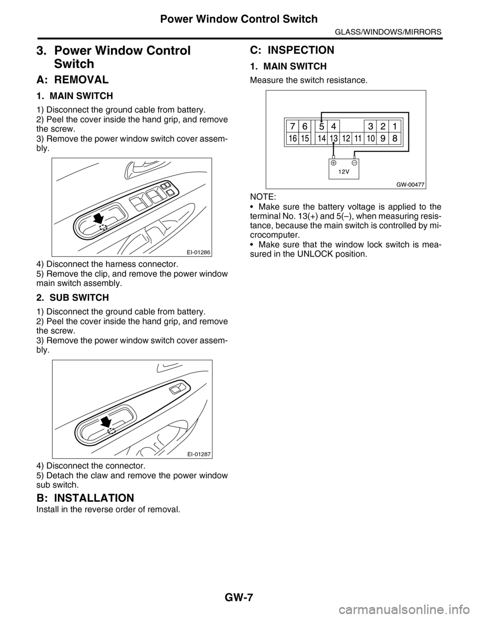
1. MAIN SWITCH
Measure the switch resistance.
NOTE:
•Make sure the battery voltage is applied to the
terminal No. 13(+) and 5(–), when measuring resis-
tance, because the main switch is controlled by mi-
crocomputer.
•Make sure that the window lock switch is mea-
sured in the UNLOCK position.EI-01286
EI-01287
Page 304 of 2453
GW-9
Front Door Glass
GLASS/WINDOWS/MIRRORS
4. Front Door Glass
A: REMOVAL
1) Remove the front door trim.
MOVAL, Door Trim.>
2) Remove the sealing cover.
MOVAL, Front Sealing Cover.>
3) Operate the power window switch to move the
glass to the position shown in the figure, and then
remove the two bolts through service holes.
4) Tilt the door glass forward, then remove the door
glass from the glass run rubber.
5) Remove the door glass.
CAUTION:
•Since the gear may be disengaged, do not
turn regulator in the closing direction after re-
moving glass.
•Avoid impact and damage to the glass.
6) Remove the bolt (A), and then remove the door
sash (B).
B: INSTALLATION
Install in the reverse order of removal.
CAUTION:
Make sure that the glass stay is placed securely
in sash.
Tightening torque:
Refer to “COMPONENT” of “General Descrip-
tion”.
COMPONENT, General Description.>
GW-00479
GW-00480
Page 305 of 2453
GW-10
Front Regulator and Motor Assembly
GLASS/WINDOWS/MIRRORS
5. Front Regulator and Motor
Assembly
A: REMOVAL
1) Remove the door glass.
MOVAL, Front Door Glass.>
2) Disconnect the motor connector.
3) Remove the four bolts and two nuts to remove
regulator assembly.
4) Remove the screws to remove motor assembly.
NOTE:
When removing the motor assembly, secure the
arm correctly. Otherwise the regulator arm moves
with the force of balancing spring.
B: INSTALLATION
Install in the reverse order of removal.
Tightening torque:
Refer to “COMPONENT” of “General Descrip-
tion”.
COMPONENT, General Description.>
C: INSPECTION
1) Make sure that the power window motor rotates
properly when the battery voltage is applied to the
terminals of motor connector.
2) Change polarity of battery connection to termi-
nals to ensure that the motor rotates in reverse di-
rection.
GW-00481
GW-00482
Page 308 of 2453
GW-13
Outer Mirror Assembly
GLASS/WINDOWS/MIRRORS
8. Outer Mirror Assembly
A: REMOVAL
1) Remove the mirror gusset cover.
2) Remove the door trim.
AL, Door Trim.>
3) Disconnect the mirror connector.
4) Remove the screws to remove outer mirror as-
sembly.
B: INSTALLATION
Install in the reverse order of removal.
C: INSPECTION
Check that the rearview mirror moves properly
when the battery voltage is applied to terminals.
Replace the outer mirror assembly if defective.
(1) Clip
(2) Hook
GW-00484
(2)
(1)
GW-00483
Mirror movement Terminal No.
OFF —
UP 5 (+) and 6 (–)
DOWN 6 (+) or 5 (–)
LEFT 8 (+) and 7 (–)
RIGHT 7 (+) or 8 (–)