Page 233 of 2453

EB-14
Front Hood
EXTERIOR BODY PANELS
4) Remove the front fender.
MOVAL, Front Fender.>
5) Remove the bolts of front hood hinge.
5. FRONT HOOD STRIKER
Refer to the front hood lock assembly of SL section.
Assembly.>
6. FRONT HOOD PANEL
1) Remove the front hood insulator.
2) Open the front hood to remove the window
washer hose.
3) Remove the front hood weather strip.
4) Remove the hood lock assembly.
sembly.>
5) Remove the window washer hose and nozzle.
zle.>
6) Remove the front hood damper.
7) Remove the bolt, and remove the front hood
panel from the front hood hinge.
B: INSTALLATION
Install in the reverse order of removal.
NOTE:
Be careful not to catch the window washer hose in.
Tightening torque:
Refer to “COMPONENT” of “General Descrip-
tion”.
NENT, General Description.>
C: ADJUSTMENT
1) Adjust the clearance between front hood panel
and front fender panel. Clearance must be equal at
both sides. For the dimension of clearance, refer to
“SPECIFICATION” in “General Description”.
to EB-2, SPECIFICATION, General Description.>
2) Use the hinge mounting bolts to align the front
hood longitudinal and lateral position.
3) Adjust the height at the front end of hood.
to SL-44, ADJUSTMENT, Front Hood Lock Assem-
bly.>
4) Rotate the hood buffer to adjust lateral height.
D: DISPOSAL
For the disposal procedures of front hood damper
stay, refer to the disposal procedures of rear gate
damper stay.
Gate.>
EB-00286
EB-00285
EB-00285
EB-00287
Page 234 of 2453
EB-15
Front Fender
EXTERIOR BODY PANELS
3. Front Fender
A: REMOVAL
1) Disconnect the ground cable from battery.
2) Remove the side sill guarnish.
REMOVAL, Side Garnish.>
3) Remove the front bumper.
MOVAL, Front Bumper.>
4) Remove the headlight assembly.
REMOVAL, Headlight Assembly.>
5) Remove the mud guard.
MOVAL, Mud Guard.>
6) Remove the cowl panel side.
7) Remove the bolt, and remove the front fender
panel.
B: INSTALLATION
1) Install in the reverse order of removal.
2) Install with attention to make uniform clearance
between front fender panel and front hood panel.
For the dimension of clearance, refer to “SPECIFI-
CATION” in “General Description”.
SPECIFICATION, General Description.>
Tightening torque:
7.4 N·m (0.75 kgf-m, 5.5 ft-lb)
EI-01280
(A)
EB-00279
Page 237 of 2453
EB-18
Front Sealing Cover
EXTERIOR BODY PANELS
5. Front Sealing Cover
A: REMOVAL
1) Disconnect the ground cable from battery.
2) Remove the front door trim.
MOVAL, Door Trim.>
3) Remove the door trim bracket.
4) Remove the sealing cover.
NOTE:
•Carefully remove the butyl tape. Excessive force
will easily break the cover.
•If cover gets broken, replace it with a new one.
B: INSTALLATION
1) Install in the reverse order of removal.
2) When replacing the sealing cover, use the butyl
tape.
3) Press the butyl tape-applied area firmly to pre-
vent any floating on surface.
Butyl tape:
3M 8626 or equivalent
NOTE:
•Apply a uniform bead of butyl tape.
•Attach the sealing cover, keeping it from becom-
ing wrinkled.
•Breaks in the bead will allow water leakage and
contamination.
C: INSPECTION
If the sealing cover gets damaged, replace it with a
new one.
EB-00034
EB-00018
Page 242 of 2453

EB-23
Rear Gate
EXTERIOR BODY PANELS
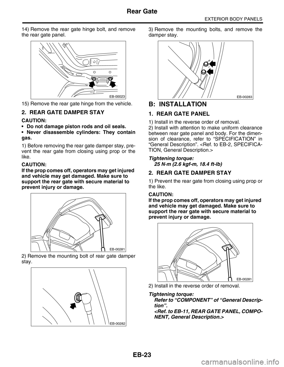
14) Remove the rear gate hinge bolt, and remove
the rear gate panel.
15) Remove the rear gate hinge from the vehicle.
2. REAR GATE DAMPER STAY
CAUTION:
•Do not damage piston rods and oil seals.
•Never disassemble cylinders: They contain
gas.
1) Before removing the rear gate damper stay, pre-
vent the rear gate from closing using prop or the
like.
CAUTION:
If the prop comes off, operators may get injured
and vehicle may get damaged. Make sure to
support the rear gate with secure material to
prevent injury or damage.
2) Remove the mounting bolt of rear gate damper
stay.
3) Remove the mounting bolts, and remove the
damper stay.
B: INSTALLATION
1. REAR GATE PANEL
1) Install in the reverse order of removal.
2) Install with attention to make uniform clearance
between rear gate panel and body. For the dimen-
sion of clearance, refer to “SPECIFICATION” in
“General Description”.
TION, General Description.>
Tightening torque:
25 N·m (2.6 kgf-m, 18.4 ft-lb)
2. REAR GATE DAMPER STAY
1) Prevent the rear gate from closing using prop or
the like.
CAUTION:
If the prop comes off, operators may get injured
and vehicle may get damaged. Make sure to
support the rear gate with secure material to
prevent injury or damage.
2) Install in the reverse order of removal.
Tightening torque:
Refer to “COMPONENT” of “General Descrip-
tion”.
NENT, General Description.>
EB-00023
EB-00281
EB-00282
EB-00283
EB-00281
Page 259 of 2453
EI-17
Front Under Cover
EXTERIOR/INTERIOR TRIM
2. Front Under Cover
A: REMOVAL
1) Remove the clips and bolts, then remove the un-
dercover.
2) Remove the clips and bolts, then remove the
front lower cover.
B: INSTALLATION
Install in the reverse order of removal.
Tightening torque:
Refer to “COMPONENT” of “General Descrip-
tion”.
NENT, General Description.>
EI-01263
EI-01264
Page 260 of 2453
EI-18
Fuel Tank Protector
EXTERIOR/INTERIOR TRIM
3. Fuel Tank Protector
A: REMOVAL
1) Remove the bolts (A) and nuts (B), and then re-
move the fuel tank protector.
B: INSTALLATION
Install in the reverse order of removal.
Tightening torque:
Bolt
17.5 N·m (1.78 kgf-m, 12.9 ft-lb)
EI-01265(A)
(A)(A)
(A)
(A)
(A)
(B)(B)(B)(B)
Page 261 of 2453
EI-19
Mud Guard
EXTERIOR/INTERIOR TRIM
4. Mud Guard
A: REMOVAL
1) Remove the wheels.
2) Loosen the screws and clips to remove mud
guard.
•Front mud guard
•Rear mud guard
B: INSTALLATION
Install in the reverse order of removal.
EI-01266
EI-01267
Page 262 of 2453
EI-20
Front Grille
EXTERIOR/INTERIOR TRIM
5. Front Grille
A: REMOVAL
1) Remove the front bumper.
MOVAL, Front Bumper.>
2) Remove the screws, and remove the front grille
from bumper face.
B: INSTALLATION
Install in the reverse order of removal.
EI-01262