Page 798 of 2453
DI-14
Rear Differential (VA–type)
DIFFERENTIALS
4. Rear Differential (VA–type)
A: REMOVAL
1) Disconnect the ground cable from the battery.
2) Release the parking brake.
3) Jack-up the vehicle.
4) Remove the rear exhaust pipe and muffler.
Pipe.>
5) Remove the heat shield cover.
6) Remove the propeller shaft.
7) Remove the connector from the rear differential
oil temperature switch.
8) Prepare the transmission jack and band.
9) Remove the DOJ of rear drive shaft from rear dif-
ferential.
10) Remove the nuts which hold the rear differen-
tial front member.
11) Support the rear differential with the transmis-
sion jack.
12) Loosen the self-lock nuts which hold the rear
differential to rear crossmember.
AT-03243
DI-00471
DI-00268
(A) Tire lever
(B) Bolt
DI-00472
(A)
(B)
DI-00358
DI-00473
DI-00269
Page 849 of 2453

DS-32
General Diagnostic Table
DRIVE SHAFT SYSTEM
9. General Diagnostic Table
A: INSPECTION
NOTE:
Vibration while cruising may be caused by an unbalanced tire, improper tire inflation pressure, improper
wheel alignment, etc.
Symptom Possible cause Corrective action
Noise or vibration from propeller shaftCenter bearing Check the center bearing.
TER BEARING FREE PLAY, INSPECTION, Pro-
peller Shaft.>
Runout of propeller shaft Check for deflection of the propeller shaft.
to DS-12, RUNOUT OF PROPELLER SHAFT,
INSPECTION, Propeller Shaft.>
Loose or gap at connections Check the joints and connectors.
JOINTS AND CONNECTIONS, INSPECTION,
Propeller Shaft.>
Check the spline and bearing.
SPLINES AND BEARING, INSPECTION, Pro-
peller Shaft.>
Abnormal wheel vibrationWheel is out of balance. Check the wheel balance.
ADJUSTMENT, Wheel Balancing.>
Fr o n t wh e el al i gn me n t Che ck t h e f r on t whe e l a li g nm en t .
INSPECTION, Wheel Alignment.>
Rear wheel alignment Check the rear wheel alignment.
INSPECTION, Wheel Alignment.>
Fr o n t s tr ut Che ck t h e f r on t st r u t . < R e f. t o F S - 21 , I N S P EC -
TION, Front Strut.>
Rear shock absorber Check the rear shock absorber.
INSPECTION, Rear Shock Absorber.>
Fr o n t d r i ve sh af t Che ck t h e f r on t dr i ve s ha f t. < R e f. t o D S - 2 7,
INSPECTION, Front Drive Shaft.>
Rear drive shaft Check the rear driveshaft.
INSPECTION, Rear Drive Shaft.>
Fr o n t h ub u ni t b e ar i n g Che ck th e f r on t h ub u n it b e ar i n g. < Re f. to DS - 2 0 ,
INSPECTION, Front Hub Unit Bearing.>
Rear hub unit bearing Check the rear hub unit bearing.
INSPECTION, Rear Hub Unit Bearing.>
Noise from the underbodyWheel is out of balance. Check the wheel balance.
ADJUSTMENT, Wheel Balancing.>
Fr o n t wh e el al i gn me n t Che ck t h e f r on t whe e l a li g nm en t .
INSPECTION, Wheel Alignment.>
Rear wheel alignment Check the rear wheel alignment.
INSPECTION, Wheel Alignment.>
Fr o n t s tr ut Che ck t h e f r on t st r u t . < R e f. t o F S - 21 , I N S P EC -
TION, Front Strut.>
Rear shock absorber Check the rear shock absorber.
INSPECTION, Rear Shock Absorber.>
Page 875 of 2453

PB-4
Parking Brake Pedal
PARKING BRAKE
2. Parking Brake Pedal
A: REMOVAL
1) Set the wheel stoppers to tires.
2) Remove the instrument panel lower cover.
to EI-36, REMOVAL, Instrument Panel Lower Cov-
er.>
3) Disconnect the parking brake switch connector.
4) Remove the parking brake lever.
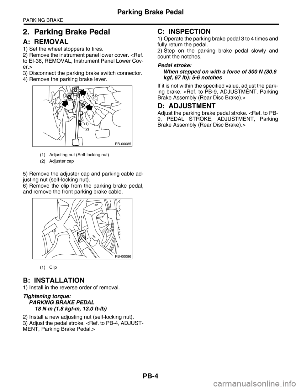
5) Remove the adjuster cap and parking cable ad-
justing nut (self-locking nut).
6) Remove the clip from the parking brake pedal,
and remove the front parking brake cable.
B: INSTALLATION
1) Install in the reverse order of removal.
Tightening torque:
PARKING BRAKE PEDAL
18 N·m (1.8 kgf-m, 13.0 ft-lb)
2) Install a new adjusting nut (self-locking nut).
3) Adjust the pedal stroke.
MENT, Parking Brake Pedal.>
C: INSPECTION
1) Operate the parking brake pedal 3 to 4 times and
fully return the pedal.
2) Step on the parking brake pedal slowly and
count the notches.
Pedal stroke:
When stepped on with a force of 300 N (30.6
kgf, 67 lb): 5-6 notches
If it is not within the specified value, adjust the park-
ing brake.
Brake Assembly (Rear Disc Brake).>
D: ADJUSTMENT
Adjust the parking brake pedal stroke.
9, PEDAL STROKE, ADJUSTMENT, Parking
Brake Assembly (Rear Disc Brake).>
(1) Adjusting nut (Self-locking nut)
(2) Adjuster cap
(1) Clip
PB-00085
(1)
(2)
PB-00086
(1)
Page 883 of 2453
PS-3
General Description
POWER ASSISTED SYSTEM (POWER STEERING)
B: COMPONENT
1. STEERING WHEEL AND COLUMN
Recommended power steering fluid Manufacturer
AT F D E X R O N I I I o r e q u i v a l e n t
B.P.
CALTEX
CASTROL
MOBIL
SHELL
TEXACO
(1) Steering shaft (5) Steering wheelTightening torque: N·m (kgf-m, ft-lb)
(2) Steering roll connector (6) Satellite switchT1: 1.2 (0.12, 0.9)
(3) Column cover (7) Cruise control switchT2: 25 (2.5, 18.1)
(4) Steering wheel lower cover (8) Airbag moduleT3: 45 (4.6, 33.2)
PS-00727
T2
T1
T3
(5)
(1)
(2)
(3)
(4)
(8)
(6)
(7)
Page 886 of 2453
PS-6
General Description
POWER ASSISTED SYSTEM (POWER STEERING)
3. OIL PUMP
(1) Pulley (9) Straight pinTightening torque: N·m (kgf-m, ft-lb)
(2) Oil seal (10) RotorT1: 3.73 (0.38, 2.75)
(3) Front casing (11) O–ringT2: 15.7 (1.6, 11.6)
(4) O–ring (12) Seal ringT3: 19.6 (2.0, 14.5)
(5) Socket (13) Rear bodyT4: 27.5 (2.8, 20.3)
(6) Pressure plate (14) ConnectorT5: 33 (3.37, 24.3)
(7) Cam ring (15) BracketT6: 36.8 (3.75, 27.1)
(8) Snap ring (16) Belt tensioner
PS-00730
T1
(5)
(4)
(2)
(1)
(3)
(10)
(9)
(6)
(7)
(8)
(14)
(6)(11)
(12)
(11)(13)
T4
T6
T3
T5
T5
T5
T2
T2
(15)
(16)
Page 892 of 2453

PS-12
Steering Wheel
POWER ASSISTED SYSTEM (POWER STEERING)
2. Steering Wheel
A: REMOVAL
1) Disconnect the ground cable from the battery.
2) Set the tire to the straight–ahead position.
3) Remove the airbag module.
MOVAL, Driver’s Airbag Module.>
WARNING:
Always refer to “Air Bag System” before per-
forming service on the air bag modules.
to AB-4, CAUTION, General Description.>
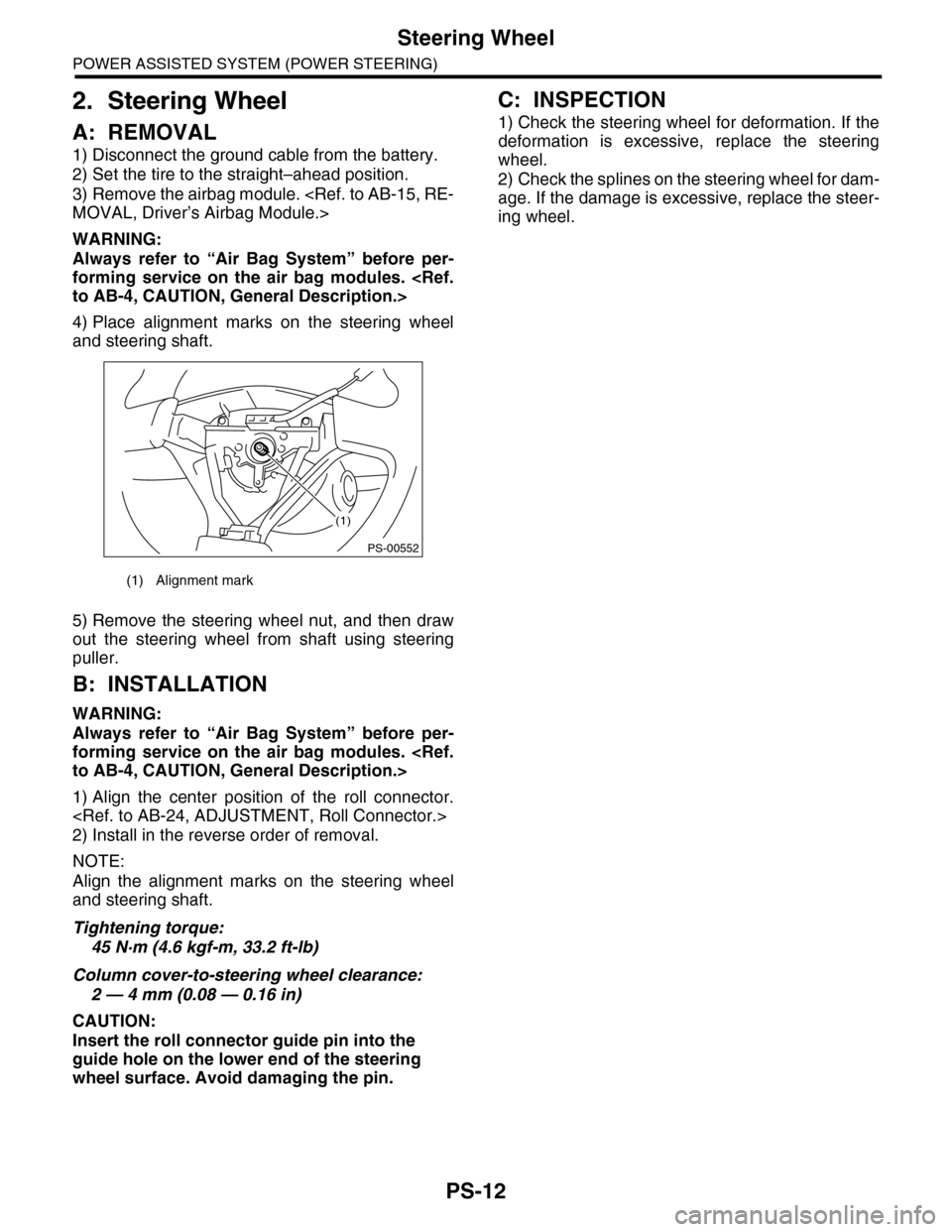
4) Place alignment marks on the steering wheel
and steering shaft.
5) Remove the steering wheel nut, and then draw
out the steering wheel from shaft using steering
puller.
B: INSTALLATION
WARNING:
Always refer to “Air Bag System” before per-
forming service on the air bag modules.
to AB-4, CAUTION, General Description.>
1) Align the center position of the roll connector.
2) Install in the reverse order of removal.
NOTE:
Align the alignment marks on the steering wheel
and steering shaft.
Tightening torque:
45 N·m (4.6 kgf-m, 33.2 ft-lb)
Column cover-to-steering wheel clearance:
2 — 4 mm (0.08 — 0.16 in)
CAUTION:
Insert the roll connector guide pin into the
guide hole on the lower end of the steering
wheel surface. Avoid damaging the pin.
C: INSPECTION
1) Check the steering wheel for deformation. If the
deformation is excessive, replace the steering
wheel.
2) Check the splines on the steering wheel for dam-
age. If the damage is excessive, replace the steer-
ing wheel.
(1) Alignment mark
(1)
PS-00552
Page 893 of 2453

PS-13
Universal Joint
POWER ASSISTED SYSTEM (POWER STEERING)
3. Universal Joint
A: REMOVAL
1) Remove the steering wheel.
MOVAL, Steering Wheel.>
2) Place alignment marks on universal joint.
3) Remove the universal joint bolt, and then re-
move the universal joint.
B: INSTALLATION
1) Align the cutout portion at serrated section of the
column shaft and yoke, then install the universal
joint into column shaft.
2) Install the universal joint to the serrations of
gearbox assembly by matching alignment marks.
3) Tighten the bolt.
Tightening torque:
24 N·m (2.4 kgf-m, 17.4 ft-lb)
CAUTION:
Excessively large tightening torque of univer-
sal joint bolts may lead to heavy steering wheel
operation.
Clearance between coupling of universal joint
to AT level gage:
15 mm (0.59 in) or more
4) Align the center position of the roll connector.
5) Install the steering wheel.
STALLATION, Steering Wheel.>
C: INSPECTION
Check for wear, damage or any other faults. Re-
place as necessary.
Service limit:
Universal joint play: 0 mm (0 in)
Maximum swing torque: 0.3 N (0.03 kgf, 0.07
lb)
Measure the swing torque of universal joint.
Service limit:
Maximum load: 3.8 N (0.39 kgf, 0.86 lb) or less
Service limit:
Maximum load: 3.8 N (0.39 kgf, 0.86 lb) or less
PS-00731
(1) Swing torque
(2) Play
(1) Yoke (Gearbox side)
(1) Yoke (Gearbox side)
PS-00033
(1)
(2)
PS-00034
PS-00035
Page 895 of 2453
PS-15
Tilt Steering Column
POWER ASSISTED SYSTEM (POWER STEERING)
4. Tilt Steering Column
A: REMOVAL
1) Remove the steering wheel.
MOVAL, Steering Wheel.>
2) Remove the universal joint.
MOVAL, Universal Joint.>
3) Remove the instrument panel lower cover under.
4) Remove the instrument panel lower cover upper.
5) Remove all connectors from the steering col-
umn.
6) Remove the two bolts under instrument panel
securing the steering column.
7) Pull out the steering shaft assembly from the
hole on toe board.
CAUTION:
•Be sure to remove the universal joint before
removing steering shaft assembly installing
bolts when removing steering shaft assembly
or when lowering it for servicing other parts.
•Do not loosen the tilt lever when the steering
column is not secured to the vehicle.
(1) Tilt steering column (2) Universal joint
PS-00732
(1)
(2)
PS-00733