Page 709 of 2453

WW-14
Wiper Relay Unit
WIPER AND WASHER SYSTEMS
6. Wiper Relay Unit
A: REMOVAL
1) Disconnect the ground cable from battery.
2) Remove the wiper arm.
MOVAL, Front Wiper Arm.>
3) Remove the cowl panel.
MOVAL, Cowl Panel.>
4) Disconnect connector (A) of the wiper motor as-
sembly.
5) Remove bolt (B) and clip (C).
6) Disconnect connector (D) of the wiper relay unit.
NOTE:
Unit body, bracket, and rubber mount is an assem-
bly component and cannot be disassembled.
B: INSTALLATION
Install in the reverse order of removal.
CAUTION:
•Do not reuse the clips. Always replace them
with new ones.
•Make sure the connector connection and clip
insertion is secure, and confirm the contact
C: INSPECTION
1) Inspect the continuity of 4 pole connector.
2) Connect the battery to the 3 pole connector and
measure the continuity of 4 pole connector.
3) When measurement value is different from the
specification, replace the wiper relay unit.
Te r m i n a l N o . S p e c i f i c a t i o n
1 and 2 Less than 1 Ω
Te r m i n a l N o .Specification3 pole connector 4 pole connector
2 and 3 1 and 4 Less than 1 Ω
1 and 2 3 and 4 Less than 1 Ω
Page 711 of 2453

WW-16
Front Wiper Motor and Link
WIPER AND WASHER SYSTEMS
8. Front Wiper Motor and Link
A: REMOVAL
1) Disconnect the ground cable from battery.
2) Remove the cowl panel.
MOVAL, Cowl Panel.>
3) Disconnect the connector of wiper motor assem-
bly.
4) Remove the bolt, and then remove the wiper as-
sembly.
NOTE:
The wiper motor and wiper link is an assembly part
and is not to be disassembled.
B: INSTALLATION
Install in the reverse order of removal.
Tightening torque:
Refer to “COMPONENT” of “General Descrip-
tion”.
NENT, General Description.>
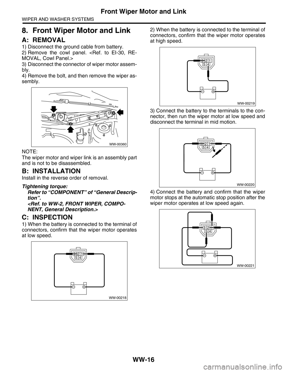
C: INSPECTION
1) When the battery is connected to the terminal of
connectors, confirm that the wiper motor operates
at low speed.
2) When the battery is connected to the terminal of
connectors, confirm that the wiper motor operates
at high speed.
3) Connect the battery to the terminals to the con-
nector, then run the wiper motor at low speed and
disconnect the terminal in mid motion.
4) Connect the battery and confirm that the wiper
motor stops at the automatic stop position after the
wiper motor operates at low speed again.
WW-00360
WW-00218
32541
32541
WW-00219
WW-00220
32541
WW-00221
32541
Page 714 of 2453

WW-19
Rear Wiper Motor
WIPER AND WASHER SYSTEMS
11.Rear Wiper Motor
A: REMOVAL
1) Disconnect the ground cable from battery.
2) Remove the rear wiper arm.
REMOVAL, Rear Wiper Arm.>
3) Remove the rear gate lower trim.
REMOVAL, Rear Gate Trim.>
4) Disconnect the harness connector of wiper mo-
tor assembly.
5) Remove the bolts to remove wiper motor assem-
bly (A).
B: INSTALLATION
1) Install in the reverse order of removal.
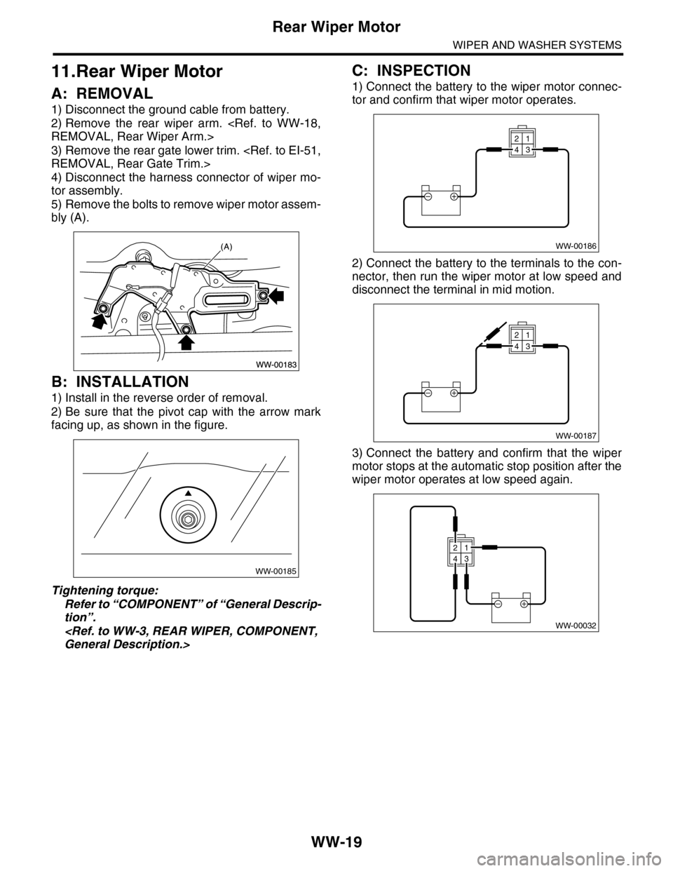
2) Be sure that the pivot cap with the arrow mark
facing up, as shown in the figure.
Tightening torque:
Refer to “COMPONENT” of “General Descrip-
tion”.
General Description.>
C: INSPECTION
1) Connect the battery to the wiper motor connec-
tor and confirm that wiper motor operates.
2) Connect the battery to the terminals to the con-
nector, then run the wiper motor at low speed and
disconnect the terminal in mid motion.
3) Connect the battery and confirm that the wiper
motor stops at the automatic stop position after the
wiper motor operates at low speed again.
WW-00185
WW-00186
21
43
WW-00187
21
43
WW-00032
21
43
Page 721 of 2453
BR-7
General Description
BRAKE
4. FRONT BRAKE PIPES AND HOSE
(1) Front brake pipe ASSY (6) GasketTightening torque: N·m (kgf-m, ft-lb)
(2) Two-way connector (7)
VDC control module and hydraulic
control unit (VDCCM&H/U)
T1: 15 (1.5, 10.8)
(3) Front brake hose RHT2: 18 (1.8, 13.0)
(4) Front brake hose LH (8) BracketT3: 19 (1.9, 14.0)
(5) Clamp (9) Master cylinderT4: 33 (3.4, 24.3)
BR-00493
T1
T2
T4
T2
T2
T2
T4
T1
T3
(8)(2)
(3)
(5)
(6)
(4)
(7)
(6)
(5)
T3
T1
T1
(1)
(9)
T1
Page 722 of 2453
BR-8
General Description
BRAKE
5. CENTER AND REAR BRAKE PIPES AND HOSE
6. BRAKE BOOSTER
(1) Center brake pipe ASSY (6) Rear brake hose bracket RHTightening torque: N·m (kgf-m, ft-lb)
(2) Two-way connector (7) Rear brake hose bracket LHT1: 15 (1.5, 10.8)
(3) Rear brake pipe ASSY (8) ClampT2: 18 (1.8, 13.0)
(4) Rear brake hose RH (9) GasketT3: 33 (3.4, 24.3)
(5) Rear brake hose LH (10) Bracket
(1) Brake booster
BR-00495(1)
Page 731 of 2453

BR-17
Front Disc Brake Assembly
BRAKE
C: DISASSEMBLY
1) Remove mud and foreign matter from the caliper
body assembly and support.
CAUTION:
Be careful not to allow foreign matter to enter
the brake hose connector.
2) Place a wooden block in the caliper body as
shown in the figure to prevent the piston from jump-
ing out and being damaged.
3) Gradually apply compressed air via the brake
hose installation hole to push the piston out.
4) Remove the piston boot.
5) Remove the piston seal from caliper body cylinder.
CAUTION:
Do not damage the cylinder and piston seal
groove.
6) Remove the guide pin and boot from caliper body.
D: ASSEMBLY
1) Clean the inside of the caliper body using brake
fluid.
2) Apply a coat of brake fluid to piston seal and in-
stall piston seal in the groove on caliper body.
3) Apply a coat of brake fluid to the inner surface of
cylinder and the entire outer surface of the piston.
4) Apply a coat of specified grease to the boot, and
fit to the groove on the ends of the cylinder.
Grease:
NIGLUBE RX-2 (Part No. K0779GA102)
5) Insert the piston into cylinder.
CAUTION:
Do not force the piston into cylinder.
6) Position the boot in the grooves on cylinder and
piston.
7) Apply a coat of specified grease to the lock pin
and guide pin outer surface, cylinder inner surface,
and boot grooves.
Grease:
NIGLUBE RX-2 (Part No. K0779GA102)
(1) Place a wood block of 30 mm (1.18 in) width.
(1) Piston seal
(1)BR-00026
BR-00240
(1)
BR-00027
(1) Piston
(2) Piston boot
(1) Piston
(2) Piston boot
(3) Caliper body
(4) Piston seal
BR-00242
(1)
(2)
BR-00243
(1)
(2)
(3)
(4)
Page 736 of 2453

BR-22
Rear Disc Brake Assembly
BRAKE
7. Rear Disc Brake Assembly
A: REMOVAL
CAUTION:
Do not allow brake fluid to come in contact with
vehicle body. If it does, wash off with water and
wipe away completely.
1) Lift-up the vehicle, and then remove the rear
wheels.
2) Disconnect the brake hose from caliper body as-
sembly.
3) Remove the caliper lower bolt.
4) Raise the caliper body, and then move it toward
vehicle center to separate it from the support.
5) Remove the support from housing.
NOTE:
Remove the support only when replacing the rotor
or support. It need not be removed when servicing
the caliper body assembly.
6) Remove mud and foreign matter from the caliper
body assembly and support.
CAUTION:
Be careful not to allow foreign matter to enter
the brake hose connector.
B: INSTALLATION
1) Install the support to the housing.
Tightening torque:
66 N·m (6.7 kgf-m, 48.7 ft-lb)
2) Apply a thin coat of Molykote M7439 to the pad
clip.
3) Apply a thin coat of Molykote AS880N (Part No.
K0777YA010) to the contact surface between the
pad and shim.
4) Install the pad to support.
5) Install the caliper body to the support.
Tightening torque:
27 N·m (2.8 kgf-m, 19.9 ft-lb)
6) Connect the brake hose using a new brake hose
gasket.
Tightening torque:
18 N·m (1.8 kgf-m, 13.0 ft-lb)
7) Bleed air from the brake system.
C: DISASSEMBLY
1) Remove the piston boot.
2) Place a wooden block in the caliper body as
shown in the figure to prevent the piston from jump-
ing out and being damaged.
3) Gradually apply compressed air via the brake
hose installation hole to push the piston out.
BR-00498
BR-00345
(1) Place a wood block of 30 mm (1.18 in) width.
BR-00041
(1)BR-00042
Page 738 of 2453

BR-24
Master Cylinder
BRAKE
8. Master Cylinder
A: REMOVAL
CAUTION:
Do not allow brake fluid to come in contact with
vehicle body. If it does, wash off with water and
wipe away completely.
1) Drain brake fluid from the reservoir tank com-
pletely.
2) Disconnect the harness connector of the fluid
level gauge.
3) Remove the brake pipe from the master cylinder.
4) Remove the master cylinder mounting nuts, and
remove the master cylinder from the brake booster.
B: INSTALLATION
1) Install in the reverse order of removal.
Tightening torque:
Master cylinder mounting nut
25 N·m (2.5 kgf-m, 18.4 ft-lb)
Brake pipe
19 N·m (1.9 kgf-m, 14.0 ft-lb)
CAUTION:
Be sure to use recommended brake fluid.
2) Bleed air from brake system.
PROCEDURE, Air Bleeding.>
C: REPLACEMENT
1) Remove mud and dirt from the surface of brake
master cylinder.
2) Secure the master cylinder in a vise.
NOTE:
To avoid damaging the master cylinder, place be-
tween aluminum plates or other material when
holding with a vise.
3) Remove the pin which secures the master cylin-
der and reservoir tank, then remove the reservoir
tank and seal.
4) While pushing in the primary piston, remove the
C-ring using pliers.
5) While pushing in the primary piston, remove the
straight pin from the port on the reservoir tank at-
tachment location using a magnet pick-up tool.
6) Extract the primary piston assembly and sec-
ondary piston assembly straight out while taking
care not to scratch the inner surface of the cylin-
ders.
7) Clean the inside of master cylinder with brake
fluid. Check the inside of the cylinder for damage,
deformation and wear. Replace the master cylinder
as assembly if faulty.
8) Apply brake fluid to the inner surface of master
cylinder and piston assembly.
9) Make sure that the inner surface of master cylin-
der and the piston assembly are free of foreign
matter. Install the primary piston assembly and the
secondary piston assembly to master cylinder,
while taking care not to scratch the master cylinder
inner surface.
10) While pushing-in the primary piston, install the
cylinder pin.
BR-00499
(1) Straight pin
BR-00169
(1)
BR-00069