Page 741 of 2453

BR-27
Brake Booster
BRAKE
B: INSTALLATION
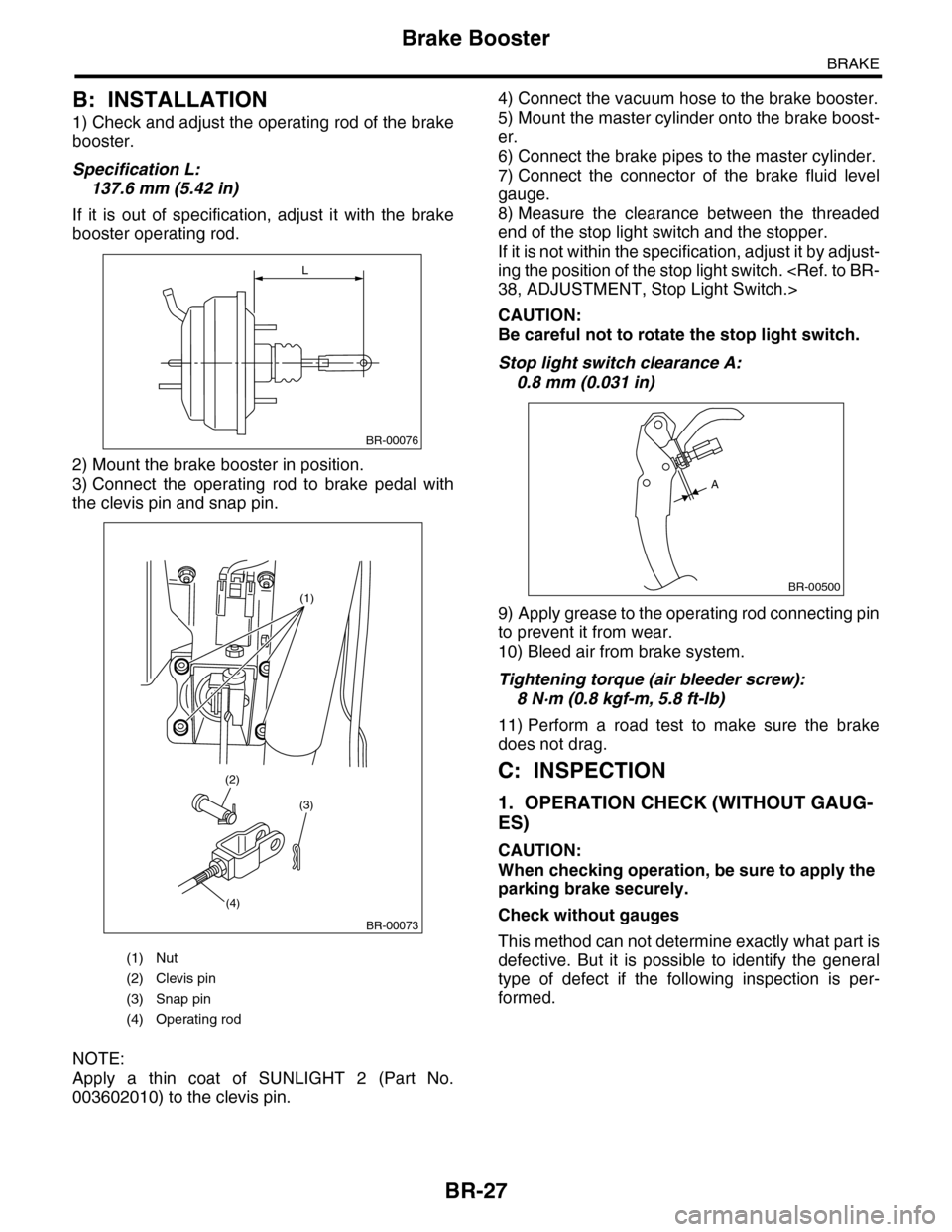
1) Check and adjust the operating rod of the brake
booster.
Specification L:
137.6 mm (5.42 in)
If it is out of specification, adjust it with the brake
booster operating rod.
2) Mount the brake booster in position.
3) Connect the operating rod to brake pedal with
the clevis pin and snap pin.
NOTE:
Apply a thin coat of SUNLIGHT 2 (Part No.
003602010) to the clevis pin.
4) Connect the vacuum hose to the brake booster.
5) Mount the master cylinder onto the brake boost-
er.
6) Connect the brake pipes to the master cylinder.
7) Connect the connector of the brake fluid level
gauge.
8) Measure the clearance between the threaded
end of the stop light switch and the stopper.
If it is not within the specification, adjust it by adjust-
ing the position of the stop light switch.
38, ADJUSTMENT, Stop Light Switch.>
CAUTION:
Be careful not to rotate the stop light switch.
Stop light switch clearance A:
0.8 mm (0.031 in)
9) Apply grease to the operating rod connecting pin
to prevent it from wear.
10) Bleed air from brake system.
Tightening torque (air bleeder screw):
8 N·m (0.8 kgf-m, 5.8 ft-lb)
11) Perform a road test to make sure the brake
does not drag.
C: INSPECTION
1. OPERATION CHECK (WITHOUT GAUG-
ES)
CAUTION:
When checking operation, be sure to apply the
parking brake securely.
Check without gauges
This method can not determine exactly what part is
defective. But it is possible to identify the general
type of defect if the following inspection is per-
formed.
(1) Nut
(2) Clevis pin
(3) Snap pin
(4) Operating rod
L
BR-00076
(1)
(3)
(4)
(2)
BR-00073
BR-00500
A
Page 750 of 2453

BR-36
Brake Pedal
BRAKE
14.Brake Pedal
A: REMOVAL
1) Remove the steering shaft.
2) Disconnect the connector (stop light switch etc.)
from the pedal bracket.
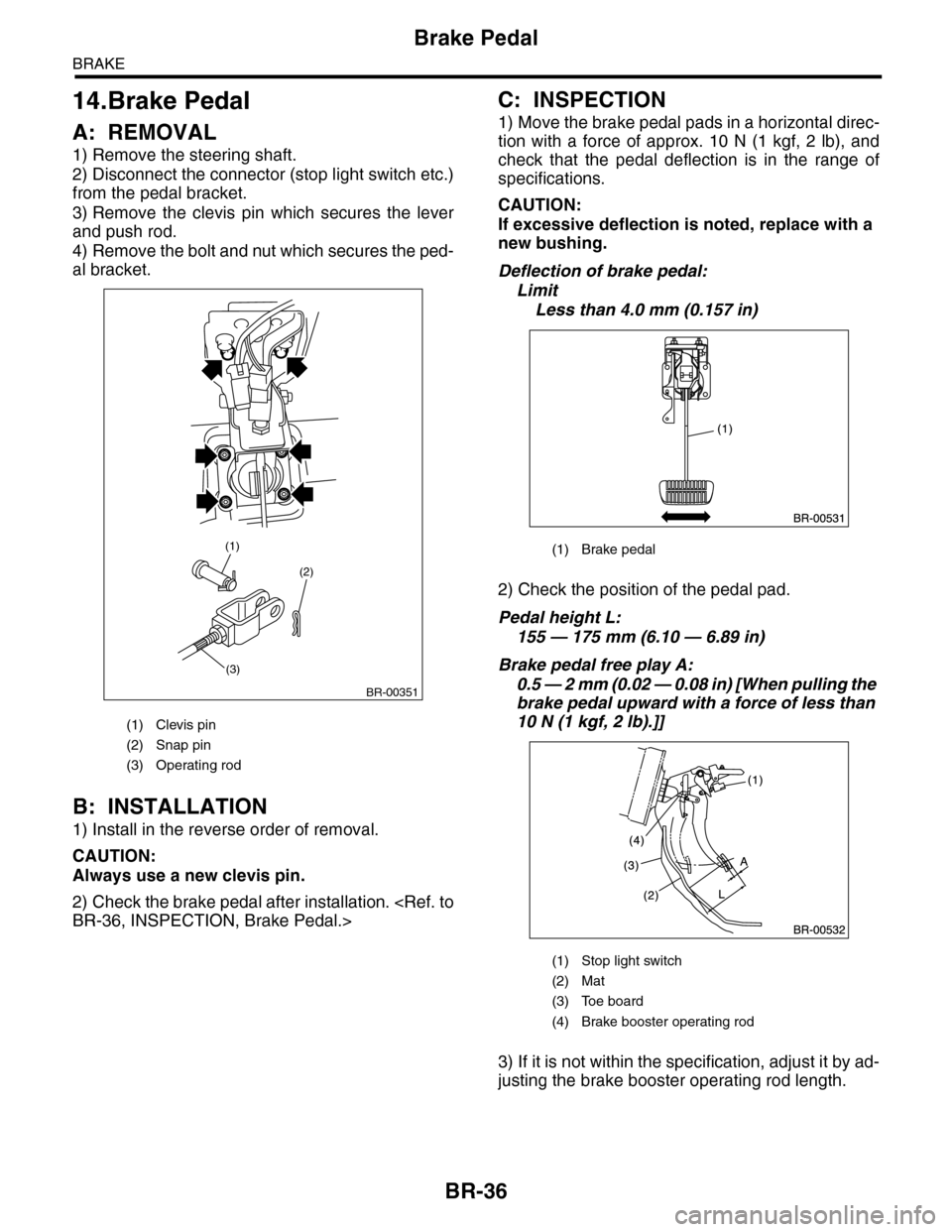
3) Remove the clevis pin which secures the lever
and push rod.
4) Remove the bolt and nut which secures the ped-
al bracket.
B: INSTALLATION
1) Install in the reverse order of removal.
CAUTION:
Always use a new clevis pin.
2) Check the brake pedal after installation.
BR-36, INSPECTION, Brake Pedal.>
C: INSPECTION
1) Move the brake pedal pads in a horizontal direc-
tion with a force of approx. 10 N (1 kgf, 2 lb), and
check that the pedal deflection is in the range of
specifications.
CAUTION:
If excessive deflection is noted, replace with a
new bushing.
Deflection of brake pedal:
Limit
Less than 4.0 mm (0.157 in)
2) Check the position of the pedal pad.
Pedal height L:
155 — 175 mm (6.10 — 6.89 in)
Brake pedal free play A:
0.5 — 2 mm (0.02 — 0.08 in) [When pulling the
brake pedal upward with a force of less than
10 N (1 kgf, 2 lb).]]
3) If it is not within the specification, adjust it by ad-
justing the brake booster operating rod length.
(1) Clevis pin
(2) Snap pin
(3) Operating rod
(2)
(3)
(1)
BR-00351
(1) Brake pedal
(1) Stop light switch
(2) Mat
(3) Toe board
(4) Brake booster operating rod
Page 751 of 2453

BR-37
Stop Light Switch
BRAKE
15.Stop Light Switch
A: REMOVAL
1) Disconnect the ground cable from the battery.
2) Disconnect the stop light switch connector.
3) Loosen the nuts, unscrew the stop light switch,
and remove stop light switch.
B: INSTALLATION
1) Install the stop light switch onto the bracket with
screws and position it with the nut.
2) Adjust the stop light switch position, and then
tighten the nut.
Switch.>
Tightening torque:
8 N·m (0.8 kgf-m, 5.8 ft-lb)
C: INSPECTION
1) If the stop light switch does not operate properly
(or if it is not secured at the specified position), re-
place with a new part.
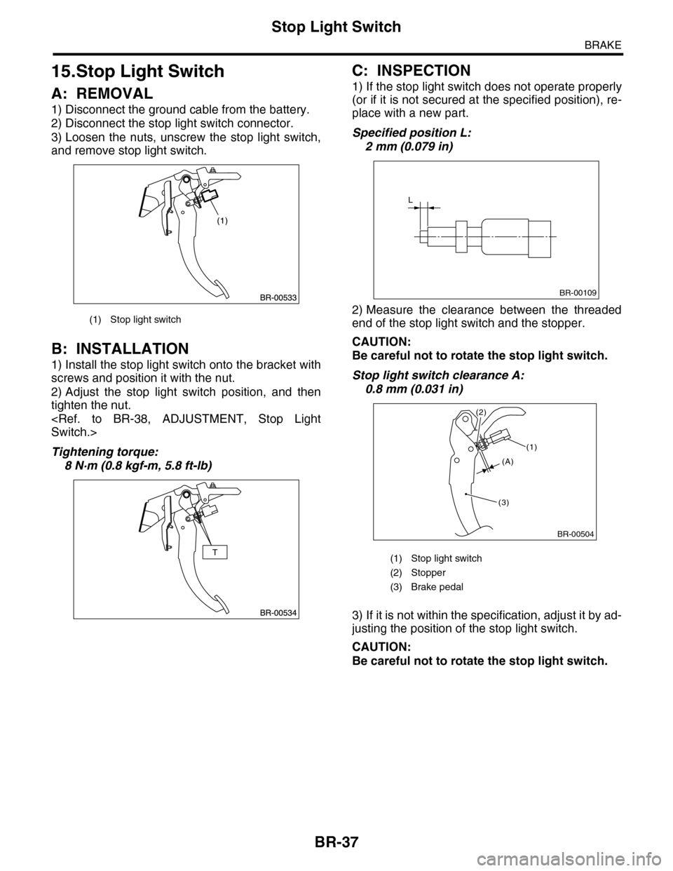
Specified position L:
2 mm (0.079 in)
2) Measure the clearance between the threaded
end of the stop light switch and the stopper.
CAUTION:
Be careful not to rotate the stop light switch.
Stop light switch clearance A:
0.8 mm (0.031 in)
3) If it is not within the specification, adjust it by ad-
justing the position of the stop light switch.
CAUTION:
Be careful not to rotate the stop light switch.
(1) Stop light switch
(1) Stop light switch
(2) Stopper
(3) Brake pedal
L
BR-00109
BR-00504
(1)
(3)
(2)
(A)
Page 753 of 2453

BR-39
Brake Vacuum Pump
BRAKE
16.Brake Vacuum Pump
A: REMOVAL
1. BRAKE VACUUM PUMP
1) Disconnect the ground cable from the battery.
2) Disconnect the brake vacuum pump connector.
3) Remove the vacuum hose.
4) Remove the bolt, and remove the brake vacuum
pump.
2. VACUUM HOSE
Remove the clip and remove the vacuum hose.
B: INSTALLATION
1. BRAKE VACUUM PUMP
Install in the reverse order of removal.
Tightening torque:
7.5 N·m (0.76 kgf-m, 5.5 ft-lb)
2. VACUUM HOSE
Install in the reverse order of removal.
CAUTION:
The vacuum hose has an installation direction.
Make sure to install in the proper direction.
C: INSPECTION
1. BRAKE VACUUM PUMP
Inspect for whether or not the pump operates when
battery voltage is applied to the connector terminal.
2. VACUUM HOSE
Check to see that air only flows in one direction,
when air is blown into or sucked from the hose.
(1) To engine
(2) Vacuum hose
(3) Vacuum pipe
(4) Marking (Marking to vacuum pipe side)
BR-00506
BR-00507
(1)
(2)(2)
(4)
(3)
ENG
Page 754 of 2453
BR-40
Brake Vacuum Sensor
BRAKE
17.Brake Vacuum Sensor
A: REMOVAL
1) Disconnect the ground cable from the battery.
2) Disconnect the brake vacuum sensor connector.
3) Remove the vacuum hose from the brake vacu-
um sensor.
4) Remove the bolt, and remove the brake vacuum
sensor.
B: INSTALLATION
Install in the reverse order of removal.
Tightening torque:
7.5 N·m (0.76 kgf-m, 5.5 ft-lb)
BR-00509
Page 757 of 2453

BVC(diag)-2
Basic Diagnostic Procedure
BRAKE VACUUM CONTROL (BVC) (DIAGNOSTICS)
1. Basic Diagnostic Procedure
A: PROCEDURE
CAUTION:
•Subaru Select Monitor is required for reading DTC, reading the current data and clearing the mem-
ory.
•Remove foreign matter (dust, water, oil, etc.) from the engine control module (ECM) connector
when removing or installing.
NOTE:
•To check the harness for broken wires or short circuits, shake problem spot or connector.
•Refer to “Check List for Interview”.
Step Check Yes No
1CHECK PRE-INSPECTION.
1) Ask the customer when and how the trou-
ble occurred using interview check list.
BVC(diag)-3, Check List for Interview.>
2) Check the error display. (Odo/trip meter)
Is “Er-bb” displayed on the
screen?
Go to step 3.Go to step 2.
2BASIC INSPECTION
Check the components which might affect the
brake vacuum control.
INSPECTION, General Description.>
Is the component that might
affect the vacuum control nor-
mal?
Go to step 3.Repair or replace
each component.
3CHECK INDICATION OF DTC.
1) Turn the ignition switch to OFF.
2) Connect the Subaru Select Monitor to data
link connector.
3) Turn the ignition switch to ON, and the Sub-
aru Select Monitor power switch to ON.
4) Read the DTC.
OPERATION, Read Diagnostic Trouble Code
(DTC).>
5) Record all DTC.
Is DTC displayed? Go to step 5.Go to step 4.
4PERFORM GENERAL DIAGNOSTICS.
Inspect using “General Diagnostic Table”.
Diagnostic Table.>
Is result of inspection OK? Finish the diagno-
sis.
Go to step 5.
5PERFORM THE DIAGNOSIS.
1) Correct the cause of trouble according to
DTC.
nostic Trouble Code (DTC).>
2) Perform the clear memory mode.
BVC(diag)-13, OPERATION, Clear Memory
Mode.>
3) Perform the inspection mode.
BVC(diag)-12, PROCEDURE, Inspection
Mode.>
4) Read the DTC.
OPERATION, Read Diagnostic Trouble Code
(DTC).>
Is DTC displayed? Repeat step 4 until
DTC is not shown.
Finish the diagno-
sis.
Page 760 of 2453

BVC(diag)-5
General Description
BRAKE VACUUM CONTROL (BVC) (DIAGNOSTICS)
3. General Description
A: CAUTION
1. SRS AIRBAG SYSTEM
Airbag system wiring harness is routed near the ABS wheel speed sensor and VDCCM&H/U.
CAUTION:
•All airbag system wiring harness and connectors are colored yellow. Do not use the electrical test
equipment on these circuits.
•Be careful not to damage the airbag system wiring harness.
B: INSPECTION
Before performing diagnosis, check the following items which might affect the brake vacuum control.
1. BATTERY
Measure the battery voltage and check electrolyte.
Standard voltage: 12 V or more
Specific gravity: 1.260 or more
2. BRAKE VACUUM HOSE
Make sure the brake vacuum hose is not cracked or loose.
C: PREPARATION TOOL
1. SPECIAL TOOL
2. GENERAL TOOL
ILLUSTRATION TOOL NUMBER DESCRIPTION REMARKS
18482AA010 CARTRIDGE Troubleshooting for the electrical system.
22771AA030 SUBARU SELECT
MONITOR KIT
Tr o u b l e s h o o t i n g f o r t h e e l e c t r i c a l s y s t e m .
TOOL NAME REMARKS
Circuit tester Used for measuring resistance, voltage and current.
Oscilloscope Used for measuring the sensor.
ST18482AA010
ST22771AA030
Page 761 of 2453
BVC(diag)-6
Electrical Component Location
BRAKE VACUUM CONTROL (BVC) (DIAGNOSTICS)
4. Electrical Component Location
A: LOCATION
(1) Brake vacuum pump relay (4) Test mode connector (6) Data link connector
(2) Brake vacuum pump (5) Engine control module (ECM) (7) Odo/trip meter
(3) Brake vacuum sensor
BR-00520
(1)
(2)(3)
(7)
(4)
(5)
(6)