2009 SUBARU TRIBECA connector
[x] Cancel search: connectorPage 896 of 2453

PS-16
Tilt Steering Column
POWER ASSISTED SYSTEM (POWER STEERING)
B: INSTALLATION
1) Insert the end of the steering shaft into the toe
board.
2) With the tilt lever secured, tighten the steering
shaft mounting bolts under instrument panel.
Tightening torque:
25 N·m (2.5 kgf-m, 18.1 ft-lb)
3) Connect all the connectors under the instrument
panel.
4) Connect the airbag system connector at the har-
ness spool.
NOTE:
Make sure to apply double lock.
5) Install the instrument panel lower cover with tilt
lever held in the lowered position.
6) Install the universal joint.
7) Align the center position of the roll connector.
8) Install the steering wheel.
CAUTION:
Insert the roll connector guide pin into the
guide hole on lower end of steering wheel sur-
face to prevent damage.
C: DISASSEMBLY
Remove the two screws securing the upper steer-
ing column covers, and the two screws securing
the combination switch, and then remove related
parts.
D: ASSEMBLY
Insert the combination switch to the upper column
shaft, and install the upper column cover. Then
route the ignition key harness and combination
switch harness between the column cover mount-
ing bosses.
Tightening torque:
1.2 N·m (0.12 kgf-m, 0.9 ft-lb)
CAUTION:
Do not overtorque the screw.
E: INSPECTION
1. BASIC INSPECTION
Measure the overall length of steering column. If
not within specification, replace it.
Overall length L:
Specification
917.5 +1.3 mm –0.3 mm (36.12 +0.051 in –0.020 in )
2. INSPECTION OF AIRBAG SYSTEM
WARNING:
Refer to “Airbag System” for airbag inspection
procedure.
PS-00734
L
Page 899 of 2453

PS-19
Steering Gearbox
POWER ASSISTED SYSTEM (POWER STEERING)
6) After tightening the castle nut to the specified
tightening torque, tighten it further within 60° until
the cotter pin hole is aligned with slot in the nut. Fit
the cotter pin into the nut, and then bend the pin to
lock.
7) Install the front stabilizer.
8) Install the front crossmember support plate and
jack-up plate.
9) Install the front exhaust pipe assembly. (Non–
turbo model)
10) Install the under cover.
11) Install the front wheels.
12) Tighten the wheel nuts to the specified torque.
Tightening torque:
110 N·m (11.2 kgf-m, 81.1 ft-lb)
13) Lower the vehicle.
14) Remove the steering wheel.
15) Align the center position of the roll connector.
16) Install the steering wheel.
17) Connect the ground cable to the battery.
18) Pour fluid into the oil tank, and bleed air.
19) Check for fluid leaks.
20) Check the fluid level in oil tank.
21) After adjusting toe-in and steering angle, tight-
en the lock nut on tie-rod end.
Tightening torque:
85 N·m (8.7 kgf-m, 62.7 ft-lb)
NOTE:
When adjusting toe-in, hold the boot as shown to
prevent it from being rotated or twisted. If it be-
comes twisted, straighten it.
C: DISASSEMBLY
1. RACK HOUSING ASSEMBLY
1) Disconnect the four pipes from gearbox.
NOTE:
Remove the pipes C and D, which are fixed to
clamp plate, as a unit.
2) Secure the gearbox removed from vehicle in a
vise using ST.
ST1 926200000 STAND
ST2 34199AG000 BOSS D
CAUTION:
Secure the gearbox in a vise using ST as shown
in the figure. Do not secure the gearbox without
this ST.
3) Remove the tie-rod end and lock nut from gear-
box.
(A) Cotter pin
(B) Castle nut
(C) Tie–rod end
DS-00042
(C)
(B)
(A)
(1) Clamp
PS-00051
PS-00492
(1)
ST1
ST2
Page 921 of 2453

PS-41
Oil Pump
POWER ASSISTED SYSTEM (POWER STEERING)
7. Oil Pump
A: REMOVAL
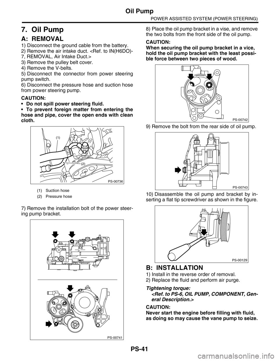
1) Disconnect the ground cable from the battery.
2) Remove the air intake duct.
3) Remove the pulley belt cover.
4) Remove the V-belts.
5) Disconnect the connector from power steering
pump switch.
6) Disconnect the pressure hose and suction hose
from power steering pump.
CAUTION:
•Do not spill power steering fluid.
•To prevent foreign matter from entering the
hose and pipe, cover the open ends with clean
cloth.
7) Remove the installation bolt of the power steer-
ing pump bracket.
8) Place the oil pump bracket in a vise, and remove
the two bolts from the front side of the oil pump.
CAUTION:
When securing the oil pump bracket in a vice,
hold the oil pump bracket with the least possi-
ble force between two pieces of wood.
9) Remove the bolt from the rear side of oil pump.
10) Disassemble the oil pump and bracket by in-
serting a flat tip screwdriver as shown in the figure.
B: INSTALLATION
1) Install in the reverse order of removal.
2) Replace the fluid and perform air purge.
Tightening torque:
CAUTION:
Never start the engine before filling with fluid,
as doing so may cause the vane pump to seize.
(1) Suction hose
(2) Pressure hose
PS-00736
(1)
(2)
PS-00741
PS-00742
PS-00743
PS-00129
Page 952 of 2453

TPM(diag)-2
Basic Diagnostic Procedure
TIRE PRESSURE MONITORING SYSTEM (DIAGNOSTICS)
1. Basic Diagnostic Procedure
A: PROCEDURE
CAUTION:
Remove foreign matter (dust, water, oil etc.) from the tire pressure monitoring control module con-
nector when removing or installing.
NOTE:
To check harness for broken wires or short circuits, shake trouble spot or connector.
Step Check Yes No
1CHECK PRE-INSPECTION.
1) Check with the user regarding when the
warning light lit or started blinking.
2) Before performing diagnostics, check the
components which might mal-affect tire pres-
sure monitor system.
Is the component that might
affect the tire pressure monitor
system normal?
Go to step 2.Repair or replace
each component.
2CHECK DIAGNOSTIC TROUBLE CODE
(DTC).
1) Turn the ignition switch to OFF.
2) Connect the Subaru Select Monitor to data
link connector.
3) Turn the ignition switch to ON and Subaru
Select Monitor to ON.
NOTE:If the communication function of the Subaru Se-
lect Monitor cannot be executed normally,
check the communication circuit.
TIALIZING IMPOSSIBLE, INSPECTION, Sub-
aru Select Monitor.>
4) Read the DTC.
(DTC).>
Is DTC displayed? Go to step 4.Go to step 3.
3PERFORM GENERAL DIAGNOSTICS.
1) Inspect using “General Diagnostic Table”.
2) Perform the clear memory mode.
Subaru Select Monitor.>
3) Perform the inspection mode.
4) Read the DTC.
OPERATION, Subaru Select Monitor.>
Check the DTC is not displayed.
Does the tire pressure warn-
ing light illuminates for about 2
seconds and then foes off after
turning on the ignition switch,
and then go out?
Finish the diagno-
sis.
Check using
“Diagnostic Proce-
dure for TPM”
WITHOUT DTC,
INSPECTION,
Subaru Select
Monitor.>
4PERFORM DIAGNOSIS.
1) Refer to “List of Diagnostic Trouble Code
(DTC).”
2) Correct the cause of trouble.
3) Perform the clear memory mode.
Subaru Select Monitor.>
4) Perform the drive test.
Drive the vehicle at a speed more than 40 km/h
(25 MPH) for at least 10 minutes.
5) Read the DTC.
OPERATION, Subaru Select Monitor.>
Is DTC displayed? Repeat steps 1 to
4 until DTC is not
shown.
Finish the diagno-
sis.
Page 958 of 2453

TPM(diag)-8
Subaru Select Monitor
TIRE PRESSURE MONITORING SYSTEM (DIAGNOSTICS)
5. Subaru Select Monitor
A: OPERATION
1. READ DIAGNOSTIC TROUBLE CODE
(DTC)
1) Prepare the Subaru Select Monitor kit.
TOOL, General Description.>
2) Connect the diagnosis cable to Subaru Select
Monitor.
3) Insert the cartridge to Subaru Select Monitor.
4) Connect the Subaru Select Monitor to data link
connector.
(1) Data link connector is located in the lower
portion of instrument panel (on the driver's
side).
(2) Connect the diagnosis cable to data link
connector.
CAUTION:
Do not connect the scan tools except for Suba-
ru Select Monitor.
5) Turn the ignition switch to ON (engine OFF) and
turn the Subaru Select Monitor switch to ON.
6) On the «Main Menu» display screen, select the
{Each System Check} and press the [YES] key.
7) On the «System Selection Menu» display
screen, select the {Tire Pressure Monitor} and
press the [YES] key.
8) Press the [YES] key after the {Model Year} is
displayed.
9) On the «Tire Pressure Monitor Diagnosis»
screen, select the {DTC Display}, and then press
the [YES] key.
NOTE:
•For details concerning operation procedure, re-
fer to the “SUBARU SELECT MONITOR OPERA-
TION MANUAL”.
•For details concerning DTCs, refer to List of Di-
agnostic Trouble Code (DTC).
•Display all the DTCs detected.
•If a particular DTC is not properly stored in mem-
ory (due to a drop in occupant detection control
module power supply, etc.) when a problem oc-
curs, the DTC which is suffixed with a question
mark appears on the Subaru Select Monitor dis-
play. This shows it may be an unreliable reading.
10) If communication is not possible between the
tire pressure monitoring control module and the
Subaru Select Monitor, check the communication
circuit.
Subaru Select Monitor.>
11) When DTC is not displayed, check the indicator
circuit and communication circuit.
Select Monitor.>
(1) Data link connector
ABS00111
ABS00112
LAN00189
(1) Power switch
ABS00114
(1)
Page 961 of 2453

TPM(diag)-11
Subaru Select Monitor
TIRE PRESSURE MONITORING SYSTEM (DIAGNOSTICS)
B: INSPECTION
1. COMMUNICATION FOR INITIALIZING IMPOSSIBLE
DETECTING CONDITION:
Defective harness connector
TROUBLE SYMPTOM:
Communication is impossible between the tire pressure monitoring control module and the Subaru Select
Monitor.
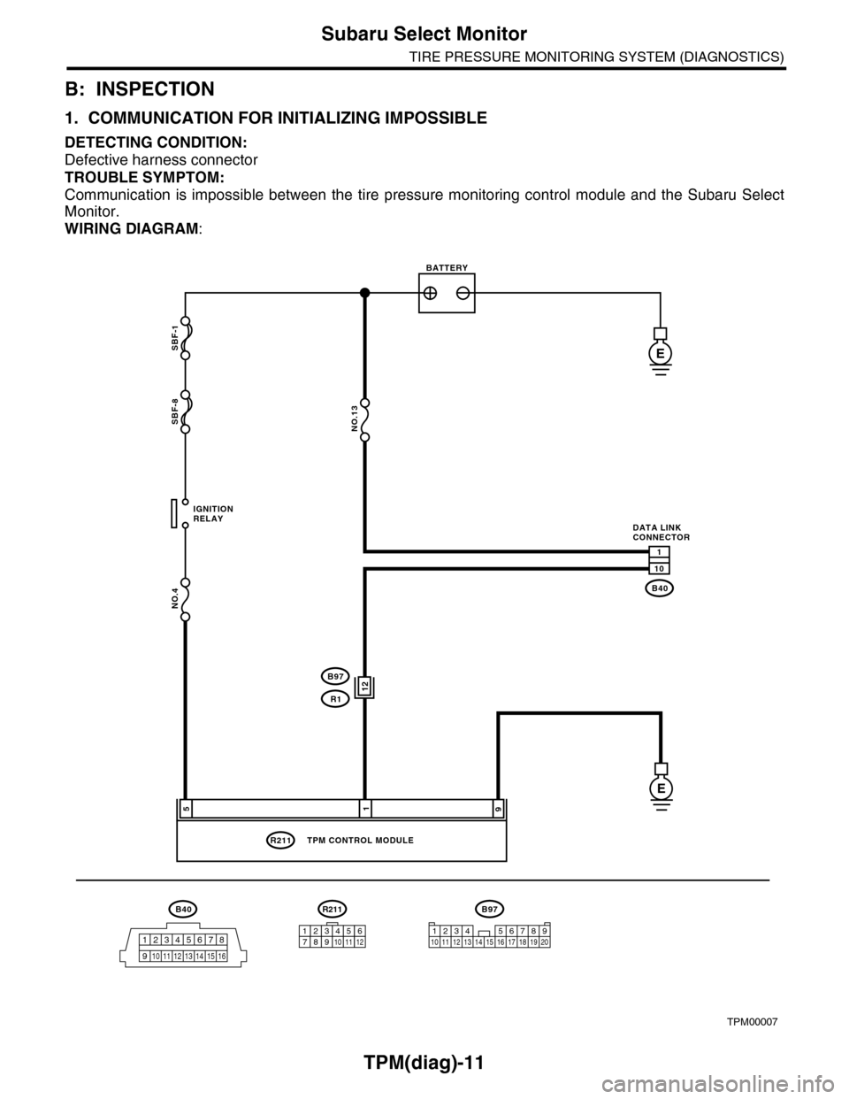
WIRING DIAGRAM:
TPM00007
B40
12345678
910 11 12 13 14 15 16
SBF-1
SBF-8
NO.4
B40
R211
E
E
1
10
195
IGNITIONRELAY
BATTERY
DATA LINKCONNECTOR
NO.13
TPM CONTROL MODULE
R211
123456789101112
12B97
R1
B97
1234 567891011 1213 14 15 16 17 18 19 20
Page 962 of 2453

TPM(diag)-12
Subaru Select Monitor
TIRE PRESSURE MONITORING SYSTEM (DIAGNOSTICS)
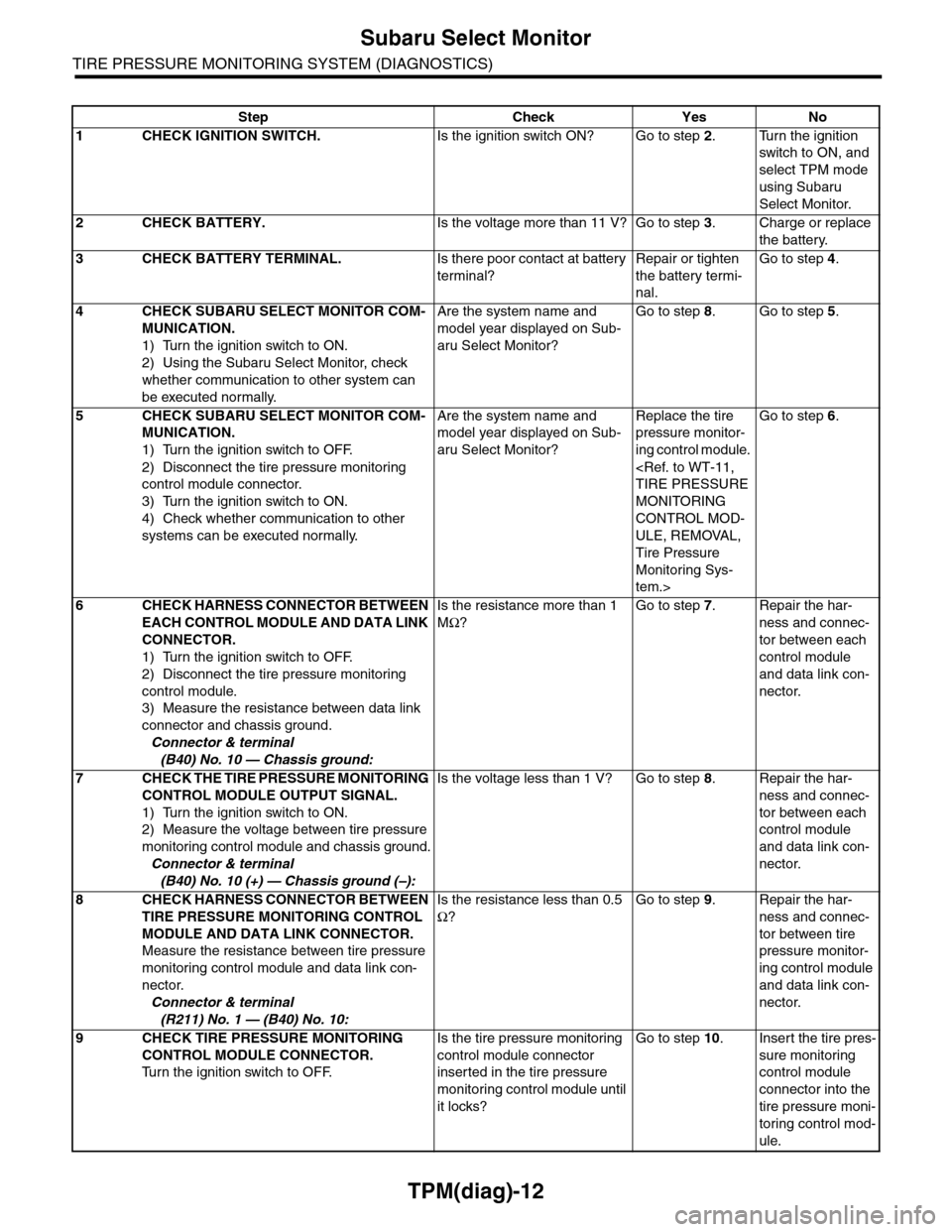
Step Check Yes No
1CHECK IGNITION SWITCH.Is the ignition switch ON? Go to step 2.Turn the ignition
switch to ON, and
select TPM mode
using Subaru
Select Monitor.
2CHECK BATTERY.Is the voltage more than 11 V? Go to step 3.Charge or replace
the battery.
3CHECK BATTERY TERMINAL.Is there poor contact at battery
terminal?
Repair or tighten
the battery termi-
nal.
Go to step 4.
4CHECK SUBARU SELECT MONITOR COM-
MUNICATION.
1) Turn the ignition switch to ON.
2) Using the Subaru Select Monitor, check
whether communication to other system can
be executed normally.
Are the system name and
model year displayed on Sub-
aru Select Monitor?
Go to step 8.Go to step 5.
5CHECK SUBARU SELECT MONITOR COM-
MUNICATION.
1) Turn the ignition switch to OFF.
2) Disconnect the tire pressure monitoring
control module connector.
3) Turn the ignition switch to ON.
4) Check whether communication to other
systems can be executed normally.
Are the system name and
model year displayed on Sub-
aru Select Monitor?
Replace the tire
pressure monitor-
ing control module.
MONITORING
CONTROL MOD-
ULE, REMOVAL,
Tire Pressure
Monitoring Sys-
tem.>
Go to step 6.
6CHECK HARNESS CONNECTOR BETWEEN
EACH CONTROL MODULE AND DATA LINK
CONNECTOR.
1) Turn the ignition switch to OFF.
2) Disconnect the tire pressure monitoring
control module.
3) Measure the resistance between data link
connector and chassis ground.
Connector & terminal
(B40) No. 10 — Chassis ground:
Is the resistance more than 1
MΩ?
Go to step 7.Repair the har-
ness and connec-
tor between each
control module
and data link con-
nector.
7CHECK THE TIRE PRESSURE MONITORING
CONTROL MODULE OUTPUT SIGNAL.
1) Turn the ignition switch to ON.
2) Measure the voltage between tire pressure
monitoring control module and chassis ground.
Connector & terminal
(B40) No. 10 (+) — Chassis ground (–):
Is the voltage less than 1 V? Go to step 8.Repair the har-
ness and connec-
tor between each
control module
and data link con-
nector.
8CHECK HARNESS CONNECTOR BETWEEN
TIRE PRESSURE MONITORING CONTROL
MODULE AND DATA LINK CONNECTOR.
Measure the resistance between tire pressure
monitoring control module and data link con-
nector.
Connector & terminal
(R211) No. 1 — (B40) No. 10:
Is the resistance less than 0.5
Ω?
Go to step 9.Repair the har-
ness and connec-
tor between tire
pressure monitor-
ing control module
and data link con-
nector.
9CHECK TIRE PRESSURE MONITORING
CONTROL MODULE CONNECTOR.
Tu r n t h e i g n i t i o n s w i t c h t o O F F.
Is the tire pressure monitoring
control module connector
inserted in the tire pressure
monitoring control module until
it locks?
Go to step 10.Insert the tire pres-
sure monitoring
control module
connector into the
tire pressure moni-
toring control mod-
ule.
Page 963 of 2453

TPM(diag)-13
Subaru Select Monitor
TIRE PRESSURE MONITORING SYSTEM (DIAGNOSTICS)
10 CHECK POWER SUPPLY CIRCUIT.
1) Turn the ignition switch to ON. (Engine
OFF)
2) Measure the ignition power voltage
between tire pressure monitoring control mod-
ule connector and chassis ground.
Connector & terminal
(R211) No. 5 (+) — Chassis ground (–):
Is the voltage 10 — 15 V? Go to step 11.Repair open circuit
of the harness
between the tire
pressure monitor-
ing control module
and battery.
11 CHECK HARNESS CONNECTOR BETWEEN
TIRE PRESSURE MONITORING CONTROL
MODULE AND CHASSIS GROUND.
1) Turn the ignition switch to OFF.
2) Disconnect the connector from the tire
pressure monitoring control module.
3) Measure the resistance of harness
between tire pressure monitoring control mod-
ule and chassis ground.
Connector & terminal
(R211) No. 9 — Chassis ground:
Is the resistance less than 0.5
Ω?
Go to step 12.Repair open circuit
of the harness of
the tire pressure
monitoring control
module.
12 CHECK POOR CONTACT OF CONNECTOR.Is there poor contact in tire
pressure monitoring control
module power supply, ground
circuit and data link connector?
Repair the con-
nector.
Replace the tire
pressure monitor-
ing control module.
MONITORING
CONTROL MOD-
ULE, REMOVAL,
Tire Pressure
Monitoring Sys-
tem.>
Step Check Yes No