2009 SUBARU TRIBECA connector
[x] Cancel search: connectorPage 1007 of 2453
VDC(diag)-15
Control Module I/O Signal
VEHICLE DYNAMICS CONTROL (VDC) (DIAGNOSTICS)
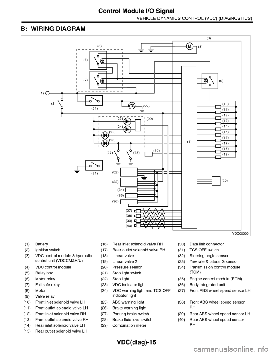
B: WIRING DIAGRAM
(1) Battery (16) Rear inlet solenoid valve RH (30) Data link connector
(2) Ignition switch (17) Rear outlet solenoid valve RH (31) TCS OFF switch
(3) VDC control module & hydraulic
control unit (VDCCM&H/U)
(18) Linear valve 1 (32) Steering angle sensor
(19) Linear valve 2 (33) Yaw rate & lateral G sensor
(4) VDC control module (20) Pressure sensor (34)
Tr a n s m i s s i o n c o n t r o l m o d u l e
(TCM)(5) Relay box (21) Stop light switch
(6) Motor relay (22) Stop light (35) Engine control module (ECM)
(7) Fail safe relay (23) VDC indicator light (36) Body integrated unit
(8) Motor (24) VDC warning light and TCS OFF
indicator light
(37)
Fr o nt A B S w he e l sp ee d se n so r L H
(9) Valve relay
(10) Front inlet solenoid valve LH (25) ABS warning light (38)
Fr o nt A B S w he e l sp e ed se n so r
RH(11) Front outlet solenoid valve LH (26) Brake warning light
(12) Front inlet solenoid valve RH (27) Parking brake switch (39) Rear ABS wheel speed sensor LH
(13) Front outlet solenoid valve RH (28) Brake fluid level switch (40) Rear ABS wheel speed sensor
RH(14) Rear inlet solenoid valve LH (29) Combination meter
(15) Rear outlet solenoid valve LH
VDC00366
M
(17)(4)(16)
(19)
(20)
(18)
(38)
(37)
(32)
(33)
(36)
(34)
(35)
(40)
(39)
(15)
(14)
(13)
(12)
(7)
(22)(21)
(31)
(23)(29)
(24)
(25)
(26)
(27) (28)(30)
(1)
(2)
(6)
(11)
(10)
(9)
(8)
(3)
(5)
Page 1008 of 2453
VDC(diag)-16
Subaru Select Monitor
VEHICLE DYNAMICS CONTROL (VDC) (DIAGNOSTICS)
6. Subaru Select Monitor
A: OPERATION
1. READ DIAGNOSTIC TROUBLE CODE
(DTC)
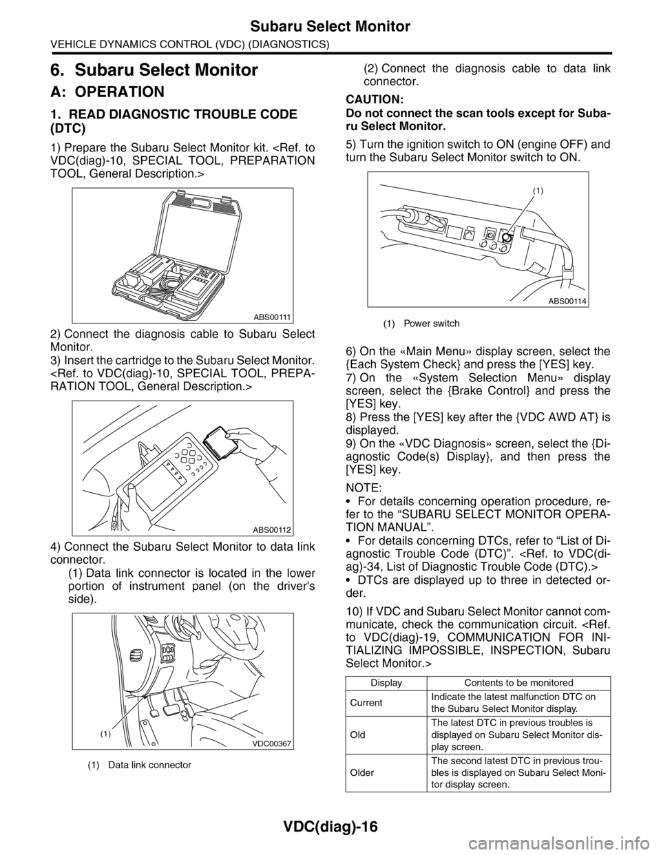
1) Prepare the Subaru Select Monitor kit.
TOOL, General Description.>
2) Connect the diagnosis cable to Subaru Select
Monitor.
3) Insert the cartridge to the Subaru Select Monitor.
4) Connect the Subaru Select Monitor to data link
connector.
(1) Data link connector is located in the lower
portion of instrument panel (on the driver's
side).
(2) Connect the diagnosis cable to data link
connector.
CAUTION:
Do not connect the scan tools except for Suba-
ru Select Monitor.
5) Turn the ignition switch to ON (engine OFF) and
turn the Subaru Select Monitor switch to ON.
6) On the «Main Menu» display screen, select the
{Each System Check} and press the [YES] key.
7) On the «System Selection Menu» display
screen, select the {Brake Control} and press the
[YES] key.
8) Press the [YES] key after the {VDC AWD AT} is
displayed.
9) On the «VDC Diagnosis» screen, select the {Di-
agnostic Code(s) Display}, and then press the
[YES] key.
NOTE:
•For details concerning operation procedure, re-
fer to the “SUBARU SELECT MONITOR OPERA-
TION MANUAL”.
•For details concerning DTCs, refer to “List of Di-
agnostic Trouble Code (DTC)”.
•DTCs are displayed up to three in detected or-
der.
10) If VDC and Subaru Select Monitor cannot com-
municate, check the communication circuit.
TIALIZING IMPOSSIBLE, INSPECTION, Subaru
Select Monitor.>
(1) Data link connector
ABS00111
ABS00112
VDC00367(1)
(1) Power switch
Display Contents to be monitored
CurrentIndicate the latest malfunction DTC on
the Subaru Select Monitor display.
Old
The latest DTC in previous troubles is
displayed on Subaru Select Monitor dis-
play screen.
Older
The second latest DTC in previous trou-
bles is displayed on Subaru Select Moni-
tor display screen.
ABS00114
(1)
Page 1011 of 2453
VDC(diag)-19
Subaru Select Monitor
VEHICLE DYNAMICS CONTROL (VDC) (DIAGNOSTICS)
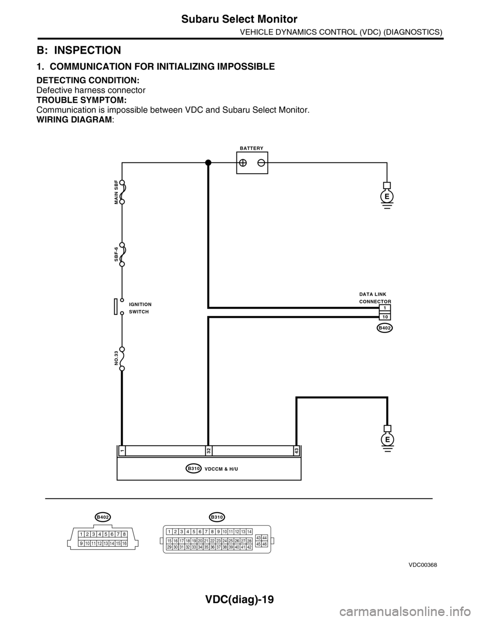
B: INSPECTION
1. COMMUNICATION FOR INITIALIZING IMPOSSIBLE
DETECTING CONDITION:
Defective harness connector
TROUBLE SYMPTOM:
Communication is impossible between VDC and Subaru Select Monitor.
WIRING DIAGRAM:
MAIN SBF
SBF-6
NO.33
B310
E
E
32431
VDCCM & H/U
B402
12345678
910 11 12 13 14 15 16
BATTERY
IGNITIONSWITCH
DATA LINKCONNECTOR
B402
10
1
B310
1234
1516171819202122232425262728293031323334353637383940414245464344568910 11 12 13 147
VDC00368
Page 1012 of 2453
VDC(diag)-20
Subaru Select Monitor
VEHICLE DYNAMICS CONTROL (VDC) (DIAGNOSTICS)
Step Check Yes No
1CHECK IGNITION SWITCH.Is the ignition switch ON? Go to step 2.Turn the ignition
switch to ON, and
select VDC mode
using Subaru
Select Monitor.
2CHECK BATTERY.
1) Turn the ignition switch to OFF.
2) Measure the battery voltage.
Is the voltage more than 11 V? Go to step 3.Charge or replace
the battery.
3CHECK BATTERY TERMINAL.Is there poor contact at battery
terminal?
Repair or tighten
the battery termi-
nal.
Go to step 4.
4CHECK SUBARU SELECT MONITOR COM-
MUNICATION.
1) Turn the ignition switch to ON.
2) Using the Subaru Select Monitor, check
whether communication to other system can
be executed normally.
Are the system name and
model year displayed on Sub-
aru Select Monitor?
Go to step 8.Go to step 5.
5CHECK SUBARU SELECT MONITOR COM-
MUNICATION.
1) Turn the ignition switch to OFF.
2) Disconnect the VDCCM&H/U connector.
3) Turn the ignition switch to ON.
4) Check whether communication to other
systems can be executed normally.
Are the system name and
model year displayed on Sub-
aru Select Monitor?
Replace the
VDCCM&H/U.
ule & Hydraulic
Control Unit
(VDCCM&H/U).>
Go to step 6.
6CHECK HARNESS CONNECTOR BETWEEN
EACH CONTROL MODULE AND DATA LINK
CONNECTOR.
1) Turn the ignition switch to OFF.
2) Disconnect the VDCCM&H/U, ECM and
TCM.
3) Measure the resistance between data link
connector and chassis ground.
Connector & terminal
(B402) No. 10 — Chassis ground:
Is the resistance more than 1
MΩ?
Go to step 7.Repair the har-
ness and connec-
tor between each
control module
and data link con-
nector.
7CHECK THE VDCCM&H/U OUTPUT SIG-
NALS.
1) Turn the ignition switch to ON.
2) Measure the voltage between data link con-
nector and chassis ground.
Connector & terminal
(B402) No. 10 (+) — Chassis ground (–):
Is the voltage less than 1 V? Go to step 8.Repair the har-
ness and connec-
tor between each
control module
and data link con-
nector.
8CHECK THE HARNESS CONNECTOR BE-
TWEEN VDCCM&H/U AND DATA LINK CON-
NECTOR.
Measure the resistance between VDCCM&H/U
connector and data link connector.
Connector & terminal
(B310) No. 32 — (B402) No. 10:
Is the resistance less than 0.5
Ω?
Go to step 9.Repair harness
and connector
between
VDCCM&H/U and
data link connec-
tor.
9CHECK INSTALLATION OF VDCCM&H/U
CONNECTOR.
Tu r n t h e i g n i t i o n s w i t c h t o O F F.
Is the VDCCM&H/U connector
inserted into VDCCM&H/U
until the clamp locks onto it?
Go to step 10.Insert VDCCM&H/
U connector into
VDCCM&H/U.
10 CHECK POWER SUPPLY CIRCUIT.
1) Turn the ignition switch to ON.(Engine OFF)
2) Measure the ignition power supply voltage
between VDCCM&H/U connector and chassis
ground.
Connector & terminal
(B310) No. 1 (+) — Chassis ground (–):
Is the voltage 10 — 15 V? Go to step 11.Repair open circuit
in harness
between
VDCCM&H/U and
battery.
Page 1013 of 2453
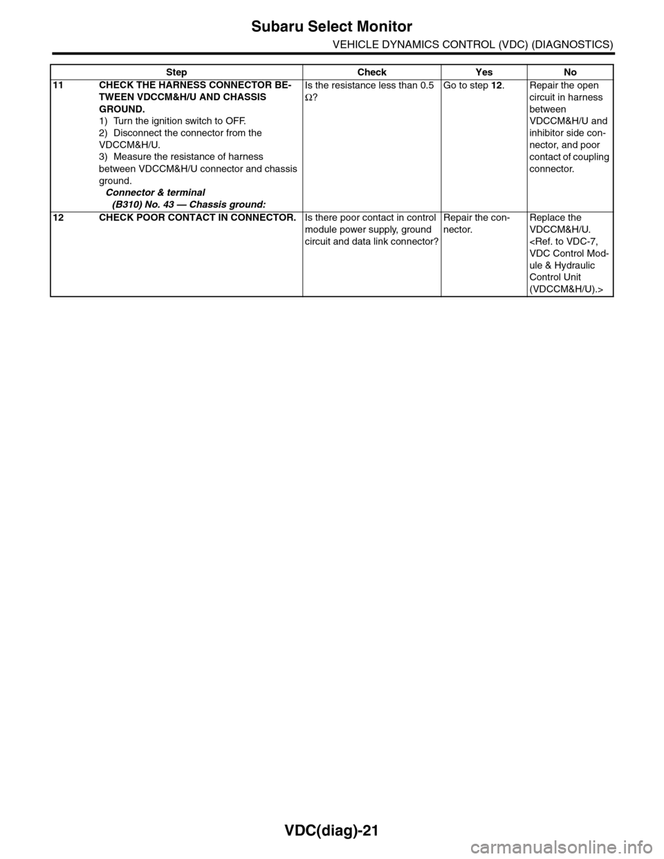
VDC(diag)-21
Subaru Select Monitor
VEHICLE DYNAMICS CONTROL (VDC) (DIAGNOSTICS)
11 CHECK THE HARNESS CONNECTOR BE-
TWEEN VDCCM&H/U AND CHASSIS
GROUND.
1) Turn the ignition switch to OFF.
2) Disconnect the connector from the
VDCCM&H/U.
3) Measure the resistance of harness
between VDCCM&H/U connector and chassis
ground.
Connector & terminal
(B310) No. 43 — Chassis ground:
Is the resistance less than 0.5
Ω?
Go to step 12.Repair the open
circuit in harness
between
VDCCM&H/U and
inhibitor side con-
nector, and poor
contact of coupling
connector.
12 CHECK POOR CONTACT IN CONNECTOR.Is there poor contact in control
module power supply, ground
circuit and data link connector?
Repair the con-
nector.
Replace the
VDCCM&H/U.
ule & Hydraulic
Control Unit
(VDCCM&H/U).>
Step Check Yes No
Page 1020 of 2453
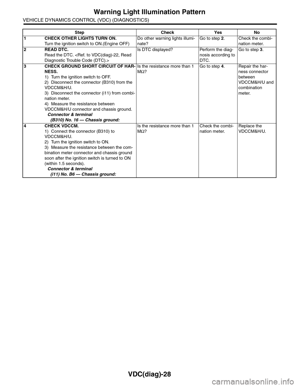
VDC(diag)-28
Warning Light Illumination Pattern
VEHICLE DYNAMICS CONTROL (VDC) (DIAGNOSTICS)
Step Check Yes No
1CHECK OTHER LIGHTS TURN ON.
Tu r n t h e i g n i t i o n s w i t c h t o O N . ( E n g i n e O F F )
Do other warning lights illumi-
nate?
Go to step 2.Check the combi-
nation meter.
2READ DTC.
Read the DTC.
Is DTC displayed? Perform the diag-
nosis according to
DTC.
Go to step 3.
3CHECK GROUND SHORT CIRCUIT OF HAR-
NESS.
1) Turn the ignition switch to OFF.
2) Disconnect the connector (B310) from the
VDCCM&H/U.
3) Disconnect the connector (i11) from combi-
nation meter.
4) Measure the resistance between
VDCCM&H/U connector and chassis ground.
Connector & terminal
(B310) No. 16 — Chassis ground:
Is the resistance more than 1
MΩ?
Go to step 4.Repair the har-
ness connector
between
VDCCM&H/U and
combination
meter.
4CHECK VDCCM.
1) Connect the connector (B310) to
VDCCM&H/U.
2) Turn the ignition switch to ON.
3) Measure the resistance between the com-
bination meter connector and chassis ground
soon after the ignition switch is turned to ON
(within 1.5 seconds).
Connector & terminal
(i11) No. B6 — Chassis ground:
Is the resistance more than 1
MΩ?
Check the combi-
nation meter.
Replace the
VDCCM&H/U.
Page 1022 of 2453
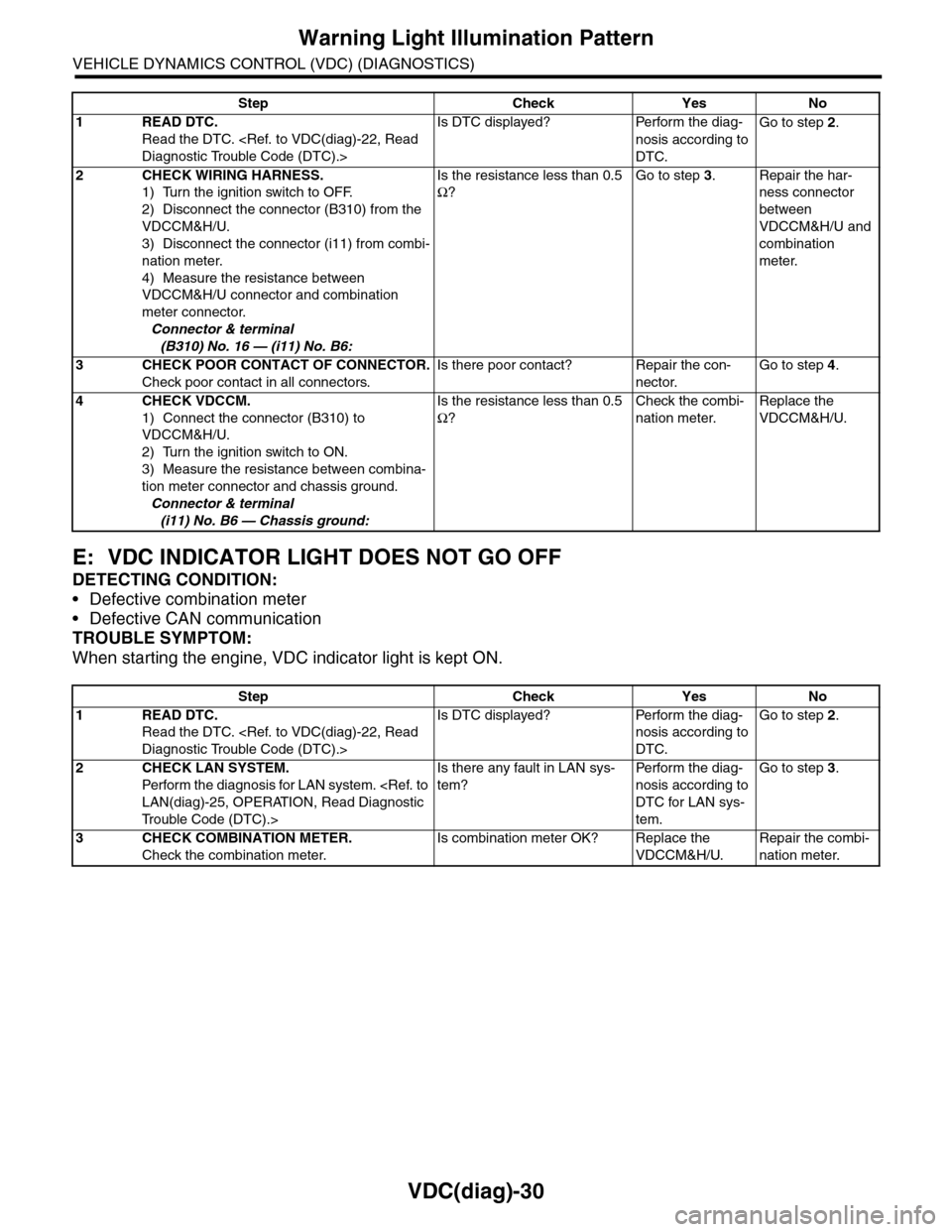
VDC(diag)-30
Warning Light Illumination Pattern
VEHICLE DYNAMICS CONTROL (VDC) (DIAGNOSTICS)
E: VDC INDICATOR LIGHT DOES NOT GO OFF
DETECTING CONDITION:
•Defective combination meter
•Defective CAN communication
TROUBLE SYMPTOM:
When starting the engine, VDC indicator light is kept ON.
Step Check Yes No
1READ DTC.
Read the DTC.
Is DTC displayed? Perform the diag-
nosis according to
DTC.
Go to step 2.
2CHECK WIRING HARNESS.
1) Turn the ignition switch to OFF.
2) Disconnect the connector (B310) from the
VDCCM&H/U.
3) Disconnect the connector (i11) from combi-
nation meter.
4) Measure the resistance between
VDCCM&H/U connector and combination
meter connector.
Connector & terminal
(B310) No. 16 — (i11) No. B6:
Is the resistance less than 0.5
Ω?
Go to step 3.Repair the har-
ness connector
between
VDCCM&H/U and
combination
meter.
3CHECK POOR CONTACT OF CONNECTOR.
Check poor contact in all connectors.
Is there poor contact? Repair the con-
nector.
Go to step 4.
4CHECK VDCCM.
1) Connect the connector (B310) to
VDCCM&H/U.
2) Turn the ignition switch to ON.
3) Measure the resistance between combina-
tion meter connector and chassis ground.
Connector & terminal
(i11) No. B6 — Chassis ground:
Is the resistance less than 0.5
Ω?
Check the combi-
nation meter.
Replace the
VDCCM&H/U.
Step Check Yes No
1READ DTC.
Read the DTC.
Is DTC displayed? Perform the diag-
nosis according to
DTC.
Go to step 2.
2CHECK LAN SYSTEM.
Perfor m the diagnosis for LAN system.
Tr o u b l e C o d e ( D T C ) . >
Is there any fault in LAN sys-
tem?
Pe r for m t h e d ia g -
nosis according to
DTC for LAN sys-
tem.
Go to step 3.
3CHECK COMBINATION METER.
Check the combination meter.
Is combination meter OK? Replace the
VDCCM&H/U.
Repair the combi-
nation meter.
Page 1024 of 2453
VDC(diag)-32
Warning Light Illumination Pattern
VEHICLE DYNAMICS CONTROL (VDC) (DIAGNOSTICS)
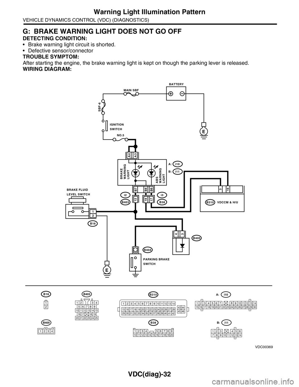
G: BRAKE WARNING LIGHT DOES NOT GO OFF
DETECTING CONDITION:
•Brake warning light circuit is shorted.
•Defective sensor/connector
TROUBLE SYMPTOM:
After starting the engine, the brake warning light is kept on though the parking lever is released.
WIRING DIAGRAM:
B16
12
B38
E
MAIN SBF
SBF-6
E
NO.5
B16
B404
A3A4
12
34B405
1234 5678910 11 12 13 14 15 16 17 18 19 20
BATTERY
IGNITIONSWITCH
BRAKE FLUIDLEVEL SWITCH
PARKING BRAKESWITCH
BRAKEWARNINGLIGHTABSWARNINGLIGHT
316
B310B38
i3
i10A:
i11B:
VDCCM & H/U
B8
1817B403
i2B7B6
VDC00369
12
B405
1234
B403
567821943
10
2422 23 25
1112131415161718192021
B310
1234
1516171819202122232425262728293031323334353637383940414245464344568910 11 12 13 147
1234567891011121314
i11B:
123456789101112131415161718192021222324252627282930
i10A: