2009 SUBARU TRIBECA torque
[x] Cancel search: torquePage 1923 of 2453
ME(H6DO)-57
Cylinder Head
MECHANICAL
20.Cylinder Head
A: REMOVAL
1) Remove the crank pulley.
2) Remove the front chain cover.
3) Remove the timing chain assembly.
4) Remove the cam sprocket.
5) Remove the crank sprocket.
6) Remove the rear chain cover.
7) Remove the camshaft.
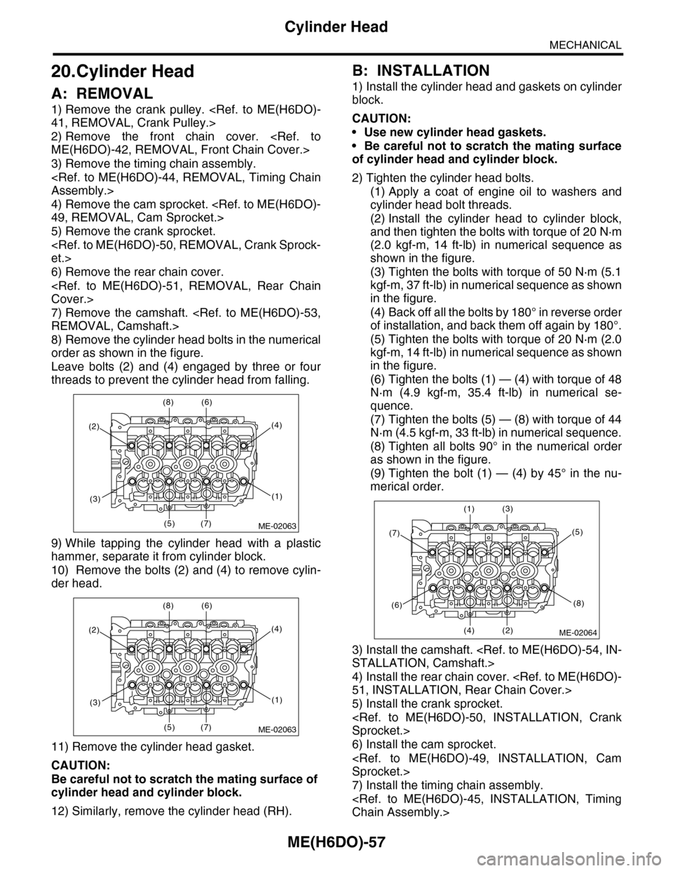
8) Remove the cylinder head bolts in the numerical
order as shown in the figure.
Leave bolts (2) and (4) engaged by three or four
threads to prevent the cylinder head from falling.
9) While tapping the cylinder head with a plastic
hammer, separate it from cylinder block.
10) Remove the bolts (2) and (4) to remove cylin-
der head.
11) Remove the cylinder head gasket.
CAUTION:
Be careful not to scratch the mating surface of
cylinder head and cylinder block.
12) Similarly, remove the cylinder head (RH).
B: INSTALLATION
1) Install the cylinder head and gaskets on cylinder
block.
CAUTION:
•Use new cylinder head gaskets.
•Be careful not to scratch the mating surface
of cylinder head and cylinder block.
2) Tighten the cylinder head bolts.
(1) Apply a coat of engine oil to washers and
cylinder head bolt threads.
(2) Install the cylinder head to cylinder block,
and then tighten the bolts with torque of 20 N·m
(2.0 kgf-m, 14 ft-lb) in numerical sequence as
shown in the figure.
(3) Tighten the bolts with torque of 50 N·m (5.1
kgf-m, 37 ft-lb) in numerical sequence as shown
in the figure.
(4) Back off all the bolts by 180° in reverse order
of installation, and back them off again by 180°.
(5) Tighten the bolts with torque of 20 N·m (2.0
kgf-m, 14 ft-lb) in numerical sequence as shown
in the figure.
(6) Tighten the bolts (1) — (4) with torque of 48
N·m (4.9 kgf-m, 35.4 ft-lb) in numerical se-
quence.
(7) Tighten the bolts (5) — (8) with torque of 44
N·m (4.5 kgf-m, 33 ft-lb) in numerical sequence.
(8) Tighten all bolts 90° in the numerical order
as shown in the figure.
(9) Tighten the bolt (1) — (4) by 45° in the nu-
merical order.
3) Install the camshaft.
4) Install the rear chain cover.
5) Install the crank sprocket.
6) Install the cam sprocket.
7) Install the timing chain assembly.
(2)
(8) (6)
(5) (7)
(4)
(1)(3)
ME-02063
(2)
(8) (6)
(5) (7)
(4)
(1)(3)
ME-02063
(7)
(1) (3)
(4) (2)
(5)
(8)(6)
ME-02064
Page 1925 of 2453
ME(H6DO)-59
Cylinder Head
MECHANICAL
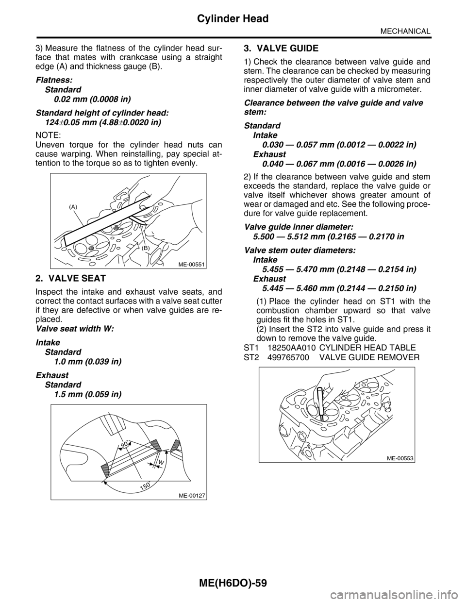
3) Measure the flatness of the cylinder head sur-
face that mates with crankcase using a straight
edge (A) and thickness gauge (B).
Flatness:
Standard
0.02 mm (0.0008 in)
Standard height of cylinder head:
124±0.05 mm (4.88±0.0020 in)
NOTE:
Uneven torque for the cylinder head nuts can
cause warping. When reinstalling, pay special at-
tention to the torque so as to tighten evenly.
2. VALVE SEAT
Inspect the intake and exhaust valve seats, and
correct the contact surfaces with a valve seat cutter
if they are defective or when valve guides are re-
placed.
Valve seat width W:
Intake
Standard
1.0 mm (0.039 in)
Exhaust
Standard
1.5 mm (0.059 in)
3. VALVE GUIDE
1) Check the clearance between valve guide and
stem. The clearance can be checked by measuring
respectively the outer diameter of valve stem and
inner diameter of valve guide with a micrometer.
Clearance between the valve guide and valve
stem:
Standard
Intake
0.030 — 0.057 mm (0.0012 — 0.0022 in)
Exhaust
0.040 — 0.067 mm (0.0016 — 0.0026 in)
2) If the clearance between valve guide and stem
exceeds the standard, replace the valve guide or
valve itself whichever shows greater amount of
wear or damaged and etc. See the following proce-
dure for valve guide replacement.
Valve guide inner diameter:
5.500 — 5.512 mm (0.2165 — 0.2170 in
Valve stem outer diameters:
Intake
5.455 — 5.470 mm (0.2148 — 0.2154 in)
Exhaust
5.445 — 5.460 mm (0.2144 — 0.2150 in)
(1) Place the cylinder head on ST1 with the
combustion chamber upward so that valve
guides fit the holes in ST1.
(2) Insert the ST2 into valve guide and press it
down to remove the valve guide.
ST1 18250AA010 CYLINDER HEAD TABLE
ST2 499765700 VALVE GUIDE REMOVER
(A)
(B)
ME-00551
ME-00127
WME-00553
Page 1930 of 2453
ME(H6DO)-64
Cylinder Block
MECHANICAL
B: INSTALLATION
1) After setting the cylinder block to ST, install the
crankshaft bearing.
ST 18232AA000 ENGINE STAND
NOTE:
Remove oil on the mating surface of bearing and
cylinder block before installation. Apply a coat of
engine oil to crankshaft pins.
2) Position the crankshaft and connecting rod on
#2, #4 and #6 cylinder block.
3) Apply liquid gasket to the mating surface of the
#1, #3 and #5 cylinder blocks, and position it on #2,
#4 and #6 cylinder blocks.
Liquid gasket:
THREE BOND 1215 (Part No. 004403007)
NOTE:
Do not allow liquid gasket to run over to O-ring
grooves, oil passages, bearing grooves, etc.
Applying liquid gasket diameter:
1.0±0.2 mm (0.039±0.008 in)
4) Apply a coat of engine oil to the washer and bolt
thread.
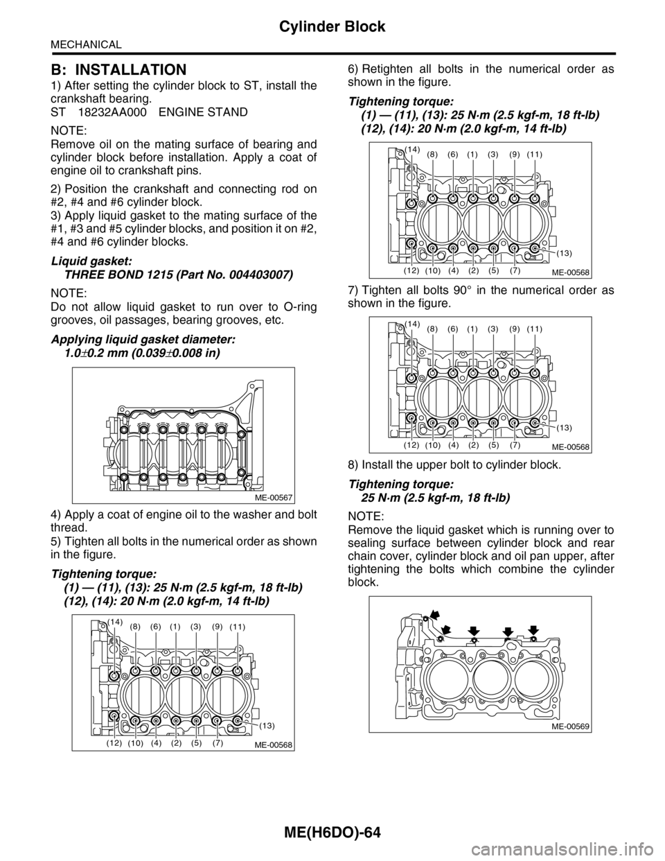
5) Tighten all bolts in the numerical order as shown
in the figure.
Tightening torque:
(1) — (11), (13): 25 N·m (2.5 kgf-m, 18 ft-lb)
(12), (14): 20 N·m (2.0 kgf-m, 14 ft-lb)
6) Retighten all bolts in the numerical order as
shown in the figure.
Tightening torque:
(1) — (11), (13): 25 N·m (2.5 kgf-m, 18 ft-lb)
(12), (14): 20 N·m (2.0 kgf-m, 14 ft-lb)
7) Tighten all bolts 90° in the numerical order as
shown in the figure.
8) Install the upper bolt to cylinder block.
Tightening torque:
25 N·m (2.5 kgf-m, 18 ft-lb)
NOTE:
Remove the liquid gasket which is running over to
sealing surface between cylinder block and rear
chain cover, cylinder block and oil pan upper, after
tightening the bolts which combine the cylinder
block.
ME-00567
(1)(6)(8)(3)(9)
(2)(4)(5)(7)(10)
(11)
(12)
(13)
(14)
ME-00568
(1)(6)(8)(3)(9)
(2)(4)(5)(7)(10)
(11)
(12)
(13)
(14)
ME-00568
(1)(6)(8)(3)(9)
(2)(4)(5)(7)(10)
(11)
(12)
(13)
(14)
ME-00568
ME-00569
Page 1933 of 2453
ME(H6DO)-67
Cylinder Block
MECHANICAL
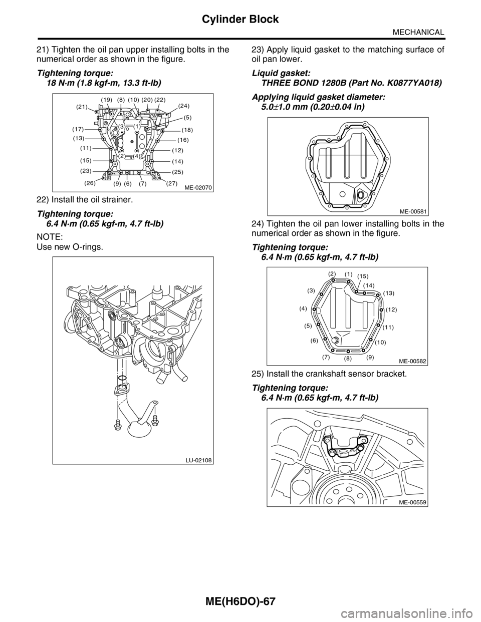
21) Tighten the oil pan upper installing bolts in the
numerical order as shown in the figure.
Tightening torque:
18 N·m (1.8 kgf-m, 13.3 ft-lb)
22) Install the oil strainer.
Tightening torque:
6.4 N·m (0.65 kgf-m, 4.7 ft-lb)
NOTE:
Use new O-rings.
23) Apply liquid gasket to the matching surface of
oil pan lower.
Liquid gasket:
THREE BOND 1280B (Part No. K0877YA018)
Applying liquid gasket diameter:
5.0±1.0 mm (0.20±0.04 in)
24) Tighten the oil pan lower installing bolts in the
numerical order as shown in the figure.
Tightening torque:
6.4 N·m (0.65 kgf-m, 4.7 ft-lb)
25) Install the crankshaft sensor bracket.
Tightening torque:
6.4 N·m (0.65 kgf-m, 4.7 ft-lb)
ME-02070
(19)
(14)
(12)
(16)
(24)(22)
(27)
(25)
(21)
(17)
(13)
(11)
(15)
(23)
(26)
(20)
(18)
(7)(6)(9)
(8) (10)
(5)
(3)
(4)
(1)
(2)
LU-02108
ME-00581
(1)(2)
(3)
(4)
(5)
(6)
(7)(8)(9)
(10)
(11)
(12)
(13)(14)
(15)
ME-00582
ME-00559
Page 1934 of 2453
ME(H6DO)-68
Cylinder Block
MECHANICAL
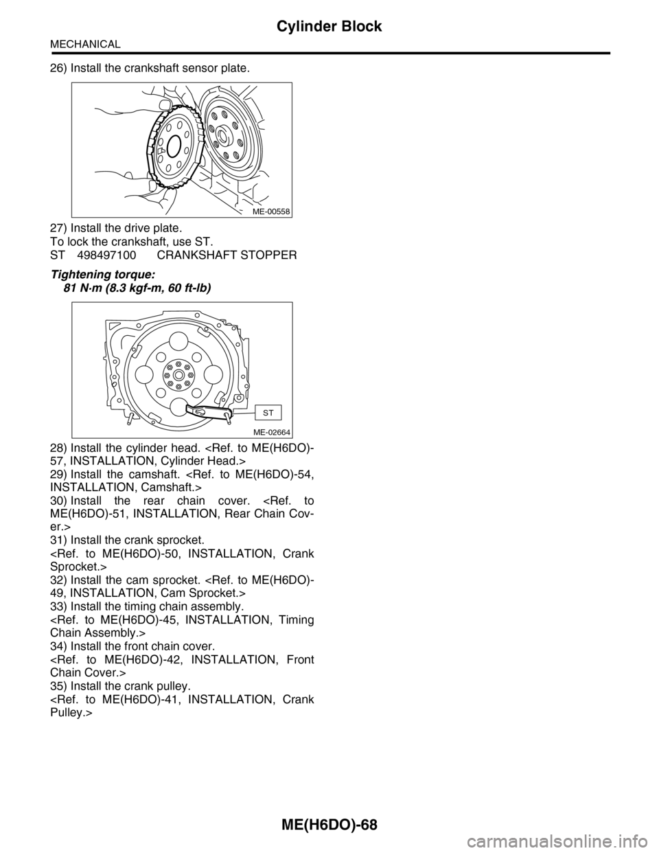
26) Install the crankshaft sensor plate.
27) Install the drive plate.
To lock the crankshaft, use ST.
ST 498497100 CRANKSHAFT STOPPER
Tightening torque:
81 N·m (8.3 kgf-m, 60 ft-lb)
28) Install the cylinder head.
29) Install the camshaft.
30) Install the rear chain cover.
er.>
31) Install the crank sprocket.
32) Install the cam sprocket.
33) Install the timing chain assembly.
34) Install the front chain cover.
35) Install the crank pulley.
ME-00558
ME-02664
ST
Page 1936 of 2453
ME(H6DO)-70
Cylinder Block
MECHANICAL
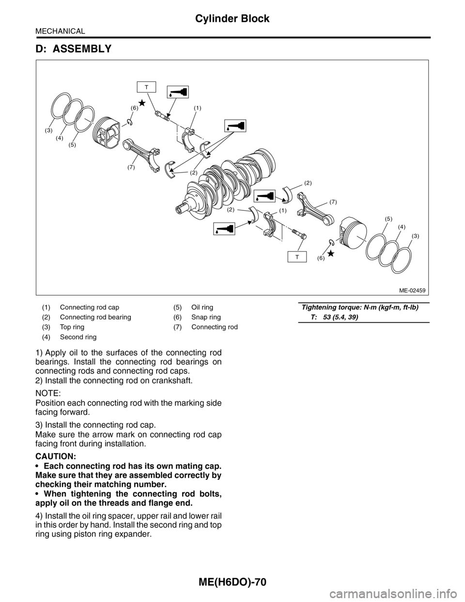
D: ASSEMBLY
1) Apply oil to the surfaces of the connecting rod
bearings. Install the connecting rod bearings on
connecting rods and connecting rod caps.
2) Install the connecting rod on crankshaft.
NOTE:
Position each connecting rod with the marking side
facing forward.
3) Install the connecting rod cap.
Make sure the arrow mark on connecting rod cap
facing front during installation.
CAUTION:
•Each connecting rod has its own mating cap.
Make sure that they are assembled correctly by
checking their matching number.
•When tightening the connecting rod bolts,
apply oil on the threads and flange end.
4) Install the oil ring spacer, upper rail and lower rail
in this order by hand. Install the second ring and top
ring using piston ring expander.
(1) Connecting rod cap (5) Oil ringTightening torque: N·m (kgf-m, ft-lb)
(2) Connecting rod bearing (6) Snap ringT: 53 (5.4, 39)
(3) Top ring (7) Connecting rod
(4) Second ring
(1)
(1)
(2)
(2)
(2)
(7)
(3)
(4)(5)
(7)
(3)
(4)
(5)
(6)
(6)T
T
ME-02459
Page 1944 of 2453
ME(H6DO)-78
Oil Switching Solenoid Valve
MECHANICAL
23.Oil Switching Solenoid Valve
A: REMOVAL
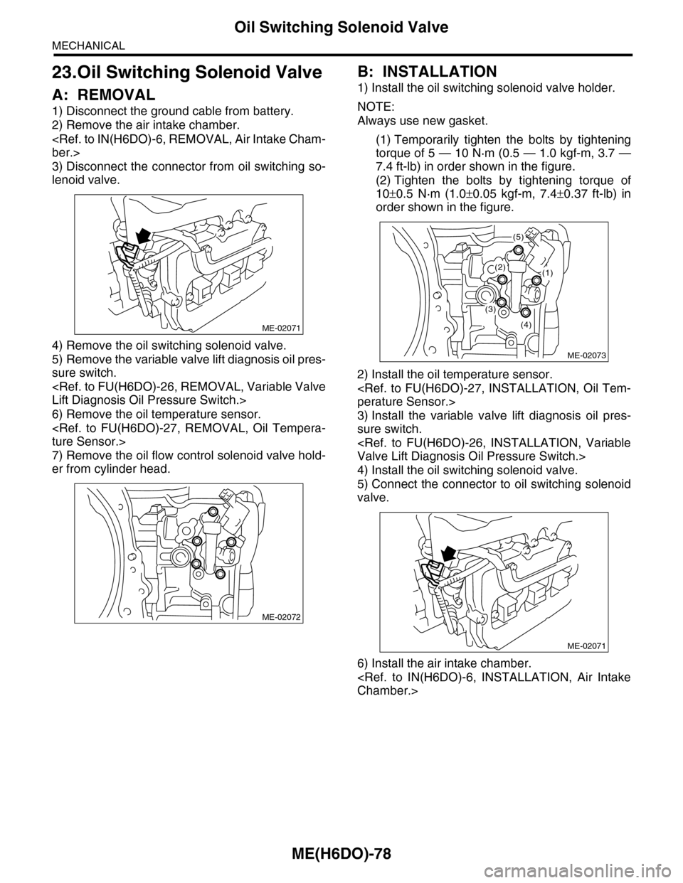
1) Disconnect the ground cable from battery.
2) Remove the air intake chamber.
3) Disconnect the connector from oil switching so-
lenoid valve.
4) Remove the oil switching solenoid valve.
5) Remove the variable valve lift diagnosis oil pres-
sure switch.
6) Remove the oil temperature sensor.
7) Remove the oil flow control solenoid valve hold-
er from cylinder head.
B: INSTALLATION
1) Install the oil switching solenoid valve holder.
NOTE:
Always use new gasket.
(1) Temporarily tighten the bolts by tightening
torque of 5 — 10 N·m (0.5 — 1.0 kgf-m, 3.7 —
7.4 ft-lb) in order shown in the figure.
(2) Tighten the bolts by tightening torque of
10±0.5 N·m (1.0±0.05 kgf-m, 7.4±0.37 ft-lb) in
order shown in the figure.
2) Install the oil temperature sensor.
3) Install the variable valve lift diagnosis oil pres-
sure switch.
4) Install the oil switching solenoid valve.
5) Connect the connector to oil switching solenoid
valve.
6) Install the air intake chamber.
ME-02071
ME-02072
ME-02073
(2)(1)
(5)
(4)
(3)
ME-02071
Page 1957 of 2453
SP(H6DO)-2
General Description
SPEED CONTROL SYSTEMS
1. General Description
A: SPECIFICATION
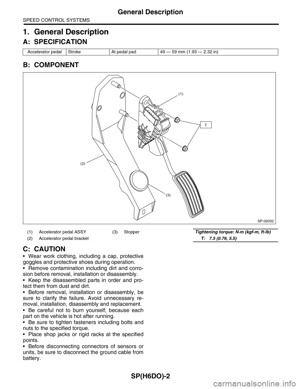
B: COMPONENT
C: CAUTION
•Wear work clothing, including a cap, protective
goggles and protective shoes during operation.
•Remove contamination including dirt and corro-
sion before removal, installation or disassembly.
•Keep the disassembled parts in order and pro-
tect them from dust and dirt.
•Before removal, installation or disassembly, be
sure to clarify the failure. Avoid unnecessary re-
moval, installation, disassembly and replacement.
•Be careful not to burn yourself, because each
part on the vehicle is hot after running.
•Be sure to tighten fasteners including bolts and
nuts to the specified torque.
•Place shop jacks or rigid racks at the specified
points.
•Before disconnecting connectors of sensors or
units, be sure to disconnect the ground cable from
battery.
Accelerator pedal Stroke At pedal pad 49 — 59 mm (1.93 — 2.32 in)
(1) Accelerator pedal ASSY (3) StopperTightening torque: N·m (kgf-m, ft-lb)
(2) Accelerator pedal bracket T: 7.5 (0.76, 5.5)
SP-02032
(1)
(2)
(3)
T