2009 SUBARU TRIBECA torque
[x] Cancel search: torquePage 1976 of 2453
SC(H6DO)-18
Starter
STARTING/CHARGING SYSTEMS
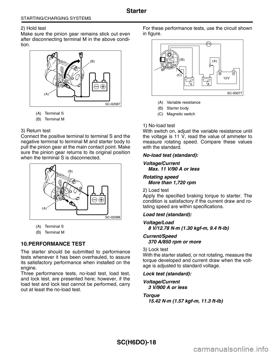
2) Hold test
Make sure the pinion gear remains stick out even
after disconnecting terminal M in the above condi-
tion.
3) Return test
Connect the positive terminal to terminal S and the
negative terminal to terminal M and starter body to
pull the pinion gear at the main contact point. Make
sure the pinion gear returns to its original position
when the terminal S is disconnected.
10.PERFORMANCE TEST
The starter should be submitted to performance
tests whenever it has been overhauled, to assure
its satisfactory performance when installed on the
engine.
Three performance tests, no-load test, load test,
and lock test, are presented here; however, if the
load test and lock test cannot be performed, carry
out at least the no-load test.
For these performance tests, use the circuit shown
in figure.
1) No-load test
With switch on, adjust the variable resistance until
the voltage is 11 V, read the value of ammeter to
measure rotating speed. Compare these values
with the standard.
No-load test (standard):
Voltage/Current
Max. 11 V/90 A or less
Rotating speed
More than 1,720 rpm
2) Load test
Apply the specified braking torque to starter. The
condition is satisfactory if the current draw and ro-
tating speed are within specifications.
Load test (standard):
Voltage/Load
8 V/12.78 N·m (1.30 kgf-m, 9.4 ft-lb)
Current/Speed
370 A/850 rpm or more
3) Lock test
With the starter stalled, or not rotating, measure the
torque developed and current draw when the volt-
age is adjusted to standard voltage.
Lock test (standard):
Voltage/Current
3 V/900 A or less
Torque
15.42 N·m (1.57 kgf-m, 11.3 ft-lb)
(A) Terminal S
(B) Terminal M
(A) Terminal S
(B) Terminal M
SC-02087
(B)
(A)
SC-02088
(A)
(B)
(A) Variable resistance
(B) Starter body
(C) Magnetic switch
SC-00077
(A)(B)
(C)12V
+
AV
BS
M
Page 1977 of 2453
SC(H6DO)-19
Generator
STARTING/CHARGING SYSTEMS
3. Generator
A: REMOVAL
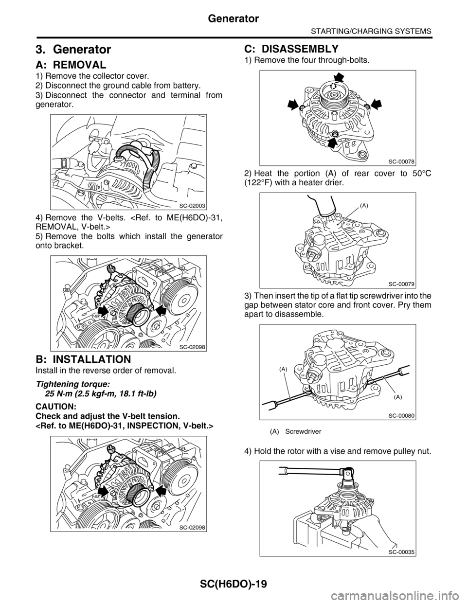
1) Remove the collector cover.
2) Disconnect the ground cable from battery.
3) Disconnect the connector and terminal from
generator.
4) Remove the V-belts.
5) Remove the bolts which install the generator
onto bracket.
B: INSTALLATION
Install in the reverse order of removal.
Tightening torque:
25 N·m (2.5 kgf-m, 18.1 ft-lb)
CAUTION:
Check and adjust the V-belt tension.
C: DISASSEMBLY
1) Remove the four through-bolts.
2) Heat the portion (A) of rear cover to 50°C
(122°F) with a heater drier.
3) Then insert the tip of a flat tip screwdriver into the
gap between stator core and front cover. Pry them
apart to disassemble.
4) Hold the rotor with a vise and remove pulley nut.
SC-02003
SC-02098
SC-02098
(A) Screwdriver
SC-00078
SC-00079
(A)
SC-00080
(A)
(A)
SC-00035
Page 1983 of 2453
SC(H6DO)-25
Battery
STARTING/CHARGING SYSTEMS
4. Battery
A: REMOVAL
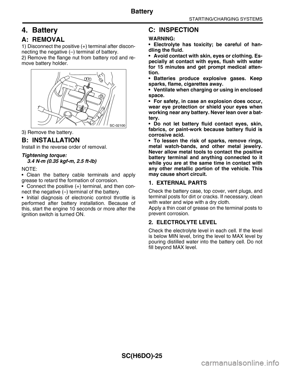
1) Disconnect the positive (+) terminal after discon-
necting the negative (–) terminal of battery.
2) Remove the flange nut from battery rod and re-
move battery holder.
3) Remove the battery.
B: INSTALLATION
Install in the reverse order of removal.
Tightening torque:
3.4 N·m (0.35 kgf-m, 2.5 ft-lb)
NOTE:
•Clean the battery cable terminals and apply
grease to retard the formation of corrosion.
•Connect the positive (+) terminal, and then con-
nect the negative (–) terminal of the battery.
•Initial diagnosis of electronic control throttle is
performed after battery installation. Because of
this, start the engine 10 seconds or more after the
ignition switch is turned ON.
C: INSPECTION
WARNING:
•Electrolyte has toxicity; be careful of han-
dling the fluid.
•Avoid contact with skin, eyes or clothing. Es-
pecially at contact with eyes, flush with water
for 15 minutes and get prompt medical atten-
tion.
•Batteries produce explosive gases. Keep
sparks, flame, cigarettes away.
•Ventilate when charging or using in enclosed
space.
•For safety, in case an explosion does occur,
wear eye protection or shield your eyes when
working near any battery. Never lean over a bat-
tery.
•Do not let battery fluid contact eyes, skin,
fabrics, or paint-work because battery fluid is
corrosive acid.
•To lessen the risk of sparks, remove rings,
metal watch-bands, and other metal jewelry.
Never allow metal tools to contact the positive
battery terminal and anything connected to it
while you are at the same time in contact with
any other metallic portion of the vehicle. This
may cause short circuit.
1. EXTERNAL PARTS
Check the battery case, top cover, vent plugs, and
terminal posts for dirt or cracks. If necessary, clean
with water and wipe with a dry cloth.
Apply a thin coat of grease on the terminal posts to
prevent corrosion.
2. ELECTROLYTE LEVEL
Check the electrolyte level in each cell. If the level
is below MIN level, bring the level to MAX level by
pouring distilled water into the battery cell. Do not
fill beyond MAX level.
SC-02100
Page 1989 of 2453
PM-6
Engine Oil
PERIODIC MAINTENANCE SERVICES
3. Engine Oil
A: REPLACEMENT
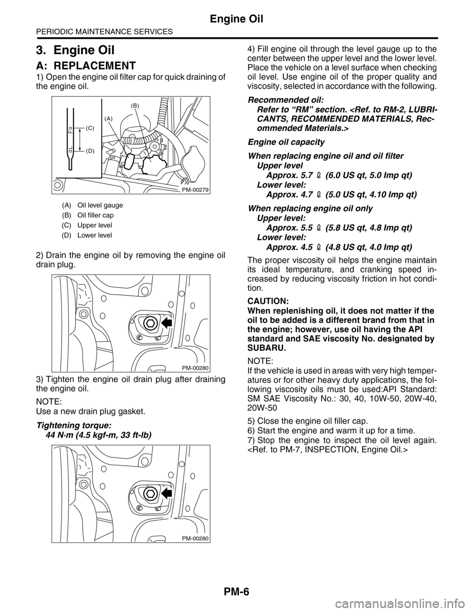
1) Open the engine oil filter cap for quick draining of
the engine oil.
2) Drain the engine oil by removing the engine oil
drain plug.
3) Tighten the engine oil drain plug after draining
the engine oil.
NOTE:
Use a new drain plug gasket.
Tightening torque:
44 N·m (4.5 kgf-m, 33 ft-lb)
4) Fill engine oil through the level gauge up to the
center between the upper level and the lower level.
Place the vehicle on a level surface when checking
oil level. Use engine oil of the proper quality and
viscosity, selected in accordance with the following.
Recommended oil:
Refer to “RM” section.
ommended Materials.>
Engine oil capacity
When replacing engine oil and oil filter
Upper level
Approx. 5.7 2 (6.0 US qt, 5.0 Imp qt)
Lower level:
Approx. 4.7 2 (5.0 US qt, 4.10 Imp qt)
When replacing engine oil only
Upper level:
Approx. 5.5 2 (5.8 US qt, 4.8 Imp qt)
Lower level:
Approx. 4.5 2 (4.8 US qt, 4.0 Imp qt)
The proper viscosity oil helps the engine maintain
its ideal temperature, and cranking speed in-
creased by reducing viscosity friction in hot condi-
tion.
CAUTION:
When replenishing oil, it does not matter if the
oil to be added is a different brand from that in
the engine; however, use oil having the API
standard and SAE viscosity No. designated by
SUBARU.
NOTE:
If the vehicle is used in areas with very high temper-
atures or for other heavy duty applications, the fol-
lowing viscosity oils must be used:API Standard:
SM SAE Viscosity No.: 30, 40, 10W-50, 20W-40,
20W-50
5) Close the engine oil filler cap.
6) Start the engine and warm it up for a time.
7) Stop the engine to inspect the oil level again.
(A) Oil level gauge
(B) Oil filler cap
(C) Upper level
(D) Lower level
PM-00279
(A)
(B)
(C)
(D)
PM-00280
PM-00280
Page 1992 of 2453

PM-9
Spark Plug
PERIODIC MAINTENANCE SERVICES
5. Spark Plug
A: REPLACEMENT
1) Remove the battery and battery carrier.
2) Remove the air cleaner case.
3) Detach the connector from ignition coil.
4) Remove the ignition coil.
5) Remove the spark plug with a spark plug socket.
6) Tighten the new spark plug lightly with hand, and
then secure with a spark plug socket to the speci-
fied torque.
Recommended spark plug:
NGK: ILFR6B
Tightening torque:
21 N·m (2.1 kgf-m, 15.2 ft-lb)
7) Tighten the ignition coil.
Tightening torque:
16 N·m (1.6 kgf-m, 11.7 ft-lb)
NOTE:
•Be sure to place the gasket between the cylinder
head and spark plug.
•If the torque wrench is not available, tighten the
spark plug until gasket contacts cylinder head; then
tighten further 1/4 to 1/2 turns.
(A) Bracket
(B) Connector
IG-02004(B)
(A)
PM-00112
Page 1999 of 2453
PM-16
Automatic Transmission Fluid
PERIODIC MAINTENANCE SERVICES
11. Automatic Transmission Fluid
A: INSPECTION
CAUTION:
The level of ATF varies with fluid temperature.
Pay attention to the fluid temperature when
checking ATF level.
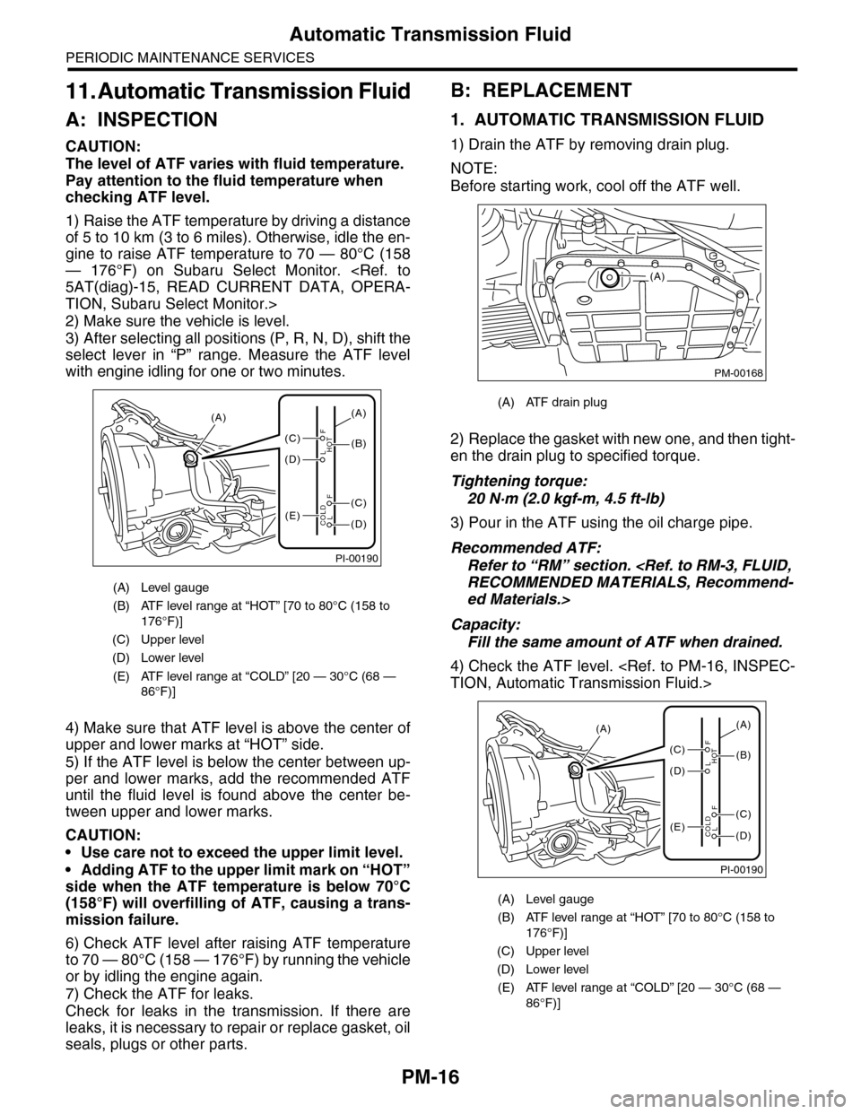
1) Raise the ATF temperature by driving a distance
of 5 to 10 km (3 to 6 miles). Otherwise, idle the en-
gine to raise ATF temperature to 70 — 80°C (158
— 176°F) on Subaru Select Monitor.
TION, Subaru Select Monitor.>
2) Make sure the vehicle is level.
3) After selecting all positions (P, R, N, D), shift the
select lever in “P” range. Measure the ATF level
with engine idling for one or two minutes.
4) Make sure that ATF level is above the center of
upper and lower marks at “HOT” side.
5) If the ATF level is below the center between up-
per and lower marks, add the recommended ATF
until the fluid level is found above the center be-
tween upper and lower marks.
CAUTION:
•Use care not to exceed the upper limit level.
•Adding ATF to the upper limit mark on “HOT”
side when the ATF temperature is below 70°C
(158°F) will overfilling of ATF, causing a trans-
mission failure.
6) Check ATF level after raising ATF temperature
to 70 — 80°C (158 — 176°F) by running the vehicle
or by idling the engine again.
7) Check the ATF for leaks.
Check for leaks in the transmission. If there are
leaks, it is necessary to repair or replace gasket, oil
seals, plugs or other parts.
B: REPLACEMENT
1. AUTOMATIC TRANSMISSION FLUID
1) Drain the ATF by removing drain plug.
NOTE:
Before starting work, cool off the ATF well.
2) Replace the gasket with new one, and then tight-
en the drain plug to specified torque.
Tightening torque:
20 N·m (2.0 kgf-m, 4.5 ft-lb)
3) Pour in the ATF using the oil charge pipe.
Recommended ATF:
Refer to “RM” section.
ed Materials.>
Capacity:
Fill the same amount of ATF when drained.
4) Check the ATF level.
(A) Level gauge
(B) ATF level range at “HOT” [70 to 80°C (158 to
176°F)]
(C) Upper level
(D) Lower level
(E) ATF level range at “COLD” [20 — 30°C (68 —
86°F)]
PI-00190
(A)
(C)
(D)
(E)(D)
(C)
(B)
(A)
F
L
F
HOT
LCOLD
(A) ATF drain plug
(A) Level gauge
(B) ATF level range at “HOT” [70 to 80°C (158 to
176°F)]
(C) Upper level
(D) Lower level
(E) ATF level range at “COLD” [20 — 30°C (68 —
86°F)]
PM-00168
(A)
PI-00190
(A)
(C)
(D)
(E)(D)
(C)
(B)
(A)
F
L
F
HOT
LCOLD
Page 2001 of 2453
PM-18
Front & Rear Differential Oil
PERIODIC MAINTENANCE SERVICES
12.Front & Rear Differential Oil
A: REPLACEMENT
1. FRONT DIFFERENTIAL
1) Drain the differential gear oil by removing drain
plug using TORX® BIT T70.
NOTE:
•Before starting work, cool off the differential gear
oil well.
•If front differential gear oil adheres to the exhaust
pipe, wipe it off completely.
2) Replace the gasket with new one, and then tight-
en the drain plug to specified torque.
Tightening torque:
70 N·m (7.1 kgf-m, 51.6 ft-lb)
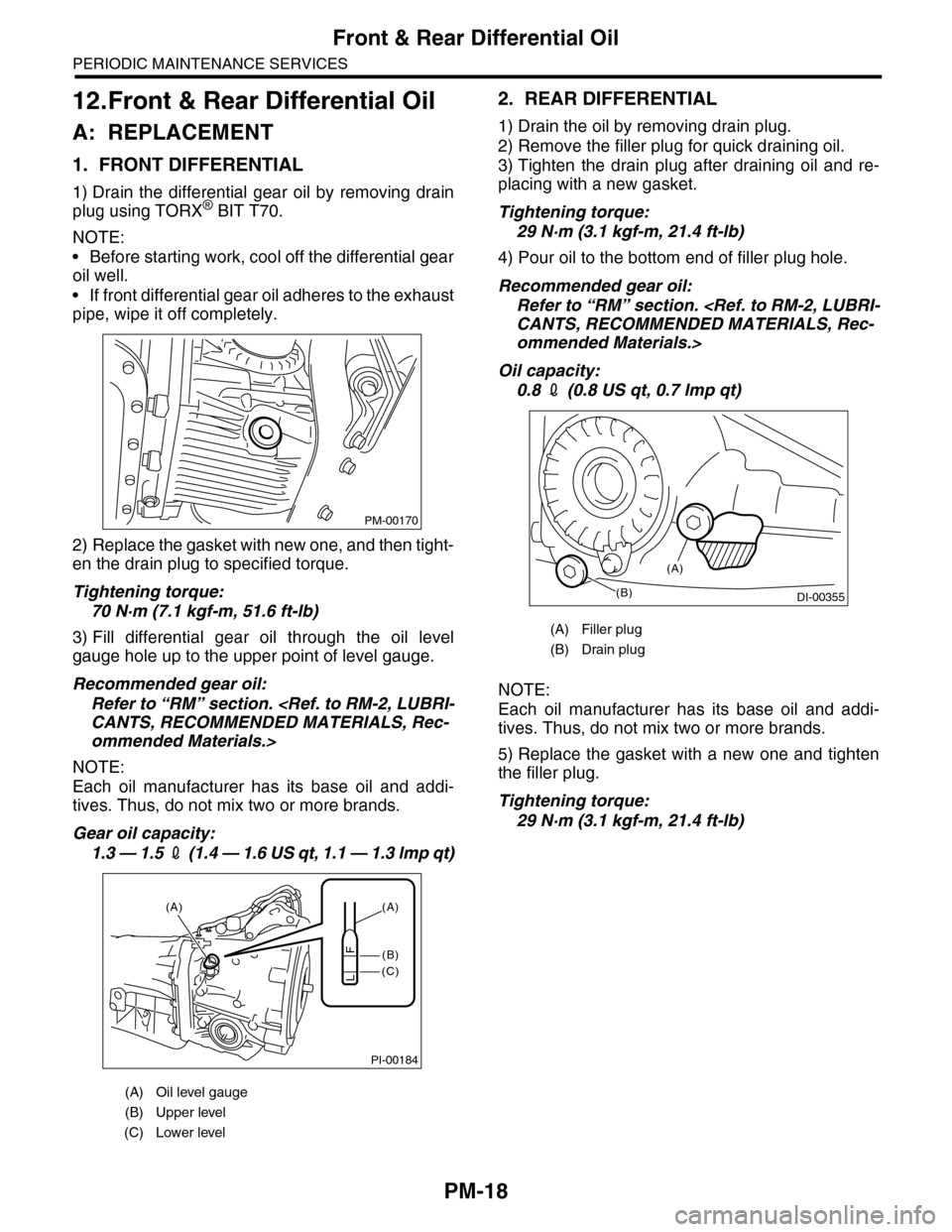
3) Fill differential gear oil through the oil level
gauge hole up to the upper point of level gauge.
Recommended gear oil:
Refer to “RM” section.
ommended Materials.>
NOTE:
Each oil manufacturer has its base oil and addi-
tives. Thus, do not mix two or more brands.
Gear oil capacity:
1.3 — 1.5 2 (1 . 4 — 1 .6 U S q t , 1 . 1 — 1 .3 lmp q t)
2. REAR DIFFERENTIAL
1) Drain the oil by removing drain plug.
2) Remove the filler plug for quick draining oil.
3) Tighten the drain plug after draining oil and re-
placing with a new gasket.
Tightening torque:
29 N·m (3.1 kgf-m, 21.4 ft-lb)
4) Pour oil to the bottom end of filler plug hole.
Recommended gear oil:
Refer to “RM” section.
ommended Materials.>
Oil capacity:
0.8 2 (0.8 US qt, 0.7 lmp qt)
NOTE:
Each oil manufacturer has its base oil and addi-
tives. Thus, do not mix two or more brands.
5) Replace the gasket with a new one and tighten
the filler plug.
Tightening torque:
29 N·m (3.1 kgf-m, 21.4 ft-lb)
(A) Oil level gauge
(B) Upper level
(C) Lower level
PM-00170
PI-00184
(A)
(C)
(B)
(A)
F
L
(A) Filler plug
(B) Drain plug
(B)DI-00355
(A)
Page 2004 of 2453
PM-21
Brake Fluid
PERIODIC MAINTENANCE SERVICES
14.Brake Fluid
A: REPLACEMENT
1) Either jack-up the vehicle and place a rigid rack
under it, or lift-up the vehicle.
2) Remove all the wheels.
3) Drain the brake fluid from master cylinder.
4) Refill the reservoir tank with recommended
brake fluid.
Recommended brake fluid:
Refer to “RM” section.
ed Materials.>
NOTE:
•Avoid mixing different brands of brake fluid to
prevent degrading the quality of fluid.
•Be careful not to allow dirt or dust to get into the
reservoir tank.
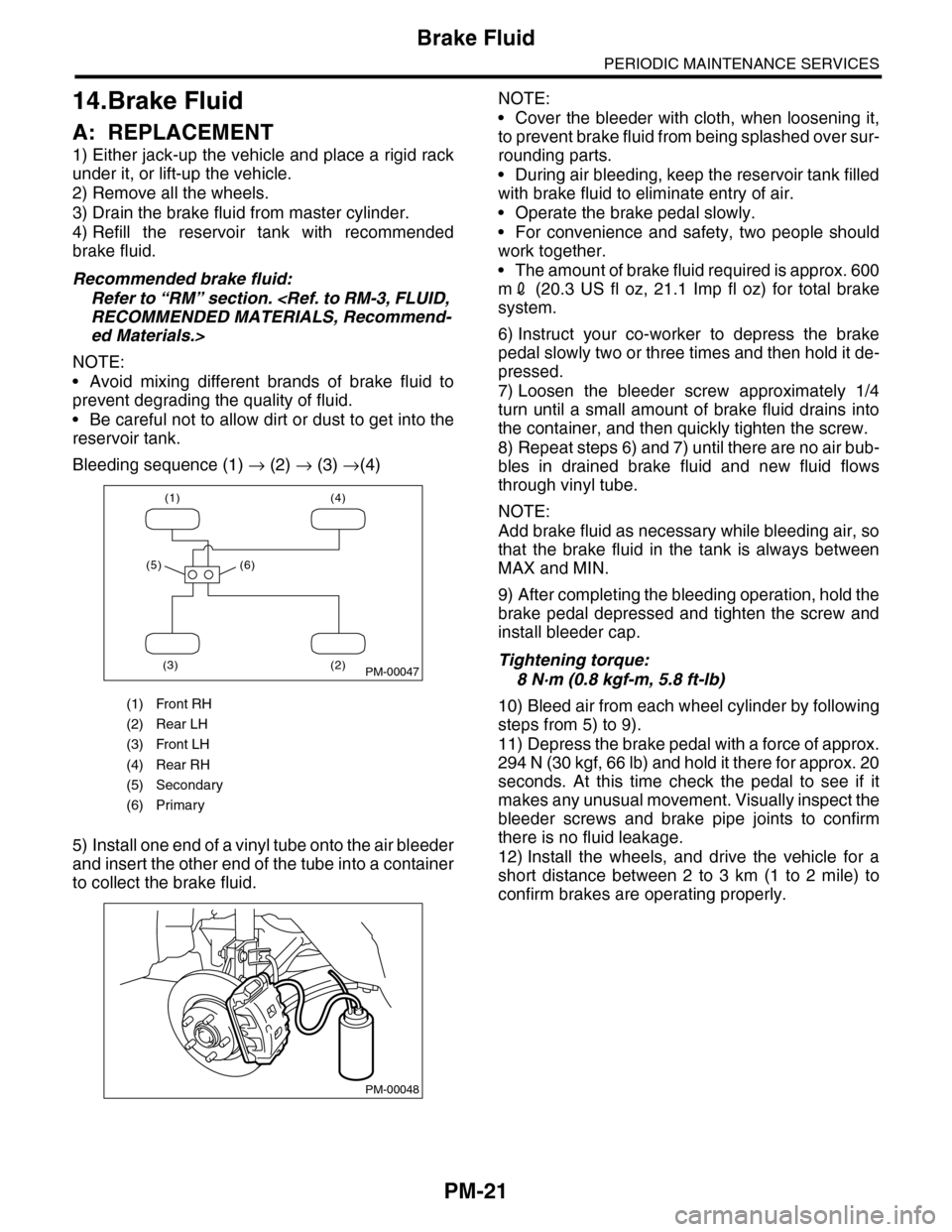
Bleeding sequence (1) → (2) → (3) →(4)
5) Install one end of a vinyl tube onto the air bleeder
and insert the other end of the tube into a container
to collect the brake fluid.
NOTE:
•Cover the bleeder with cloth, when loosening it,
to prevent brake fluid from being splashed over sur-
rounding parts.
•During air bleeding, keep the reservoir tank filled
with brake fluid to eliminate entry of air.
•Operate the brake pedal slowly.
•For convenience and safety, two people should
work together.
•The amount of brake fluid required is approx. 600
m2 (20.3 US fl oz, 21.1 Imp fl oz) for total brake
system.
6) Instruct your co-worker to depress the brake
pedal slowly two or three times and then hold it de-
pressed.
7) Loosen the bleeder screw approximately 1/4
turn until a small amount of brake fluid drains into
the container, and then quickly tighten the screw.
8) Repeat steps 6) and 7) until there are no air bub-
bles in drained brake fluid and new fluid flows
through vinyl tube.
NOTE:
Add brake fluid as necessary while bleeding air, so
that the brake fluid in the tank is always between
MAX and MIN.
9) After completing the bleeding operation, hold the
brake pedal depressed and tighten the screw and
install bleeder cap.
Tightening torque:
8 N·m (0.8 kgf-m, 5.8 ft-lb)
10) Bleed air from each wheel cylinder by following
steps from 5) to 9).
11) Depress the brake pedal with a force of approx.
294 N (30 kgf, 66 lb) and hold it there for approx. 20
seconds. At this time check the pedal to see if it
makes any unusual movement. Visually inspect the
bleeder screws and brake pipe joints to confirm
there is no fluid leakage.
12) Install the wheels, and drive the vehicle for a
short distance between 2 to 3 km (1 to 2 mile) to
confirm brakes are operating properly.
(1) Front RH
(2) Rear LH
(3) Front LH
(4) Rear RH
(5) Secondary
(6) Primary
(1) (4)
(2)(3)
(5) (6)
PM-00047
PM-00048