Page 2063 of 2453
5AT-47
Front Vehicle Speed Sensor
AUTOMATIC TRANSMISSION
14.Front Vehicle Speed Sensor
A: REMOVAL
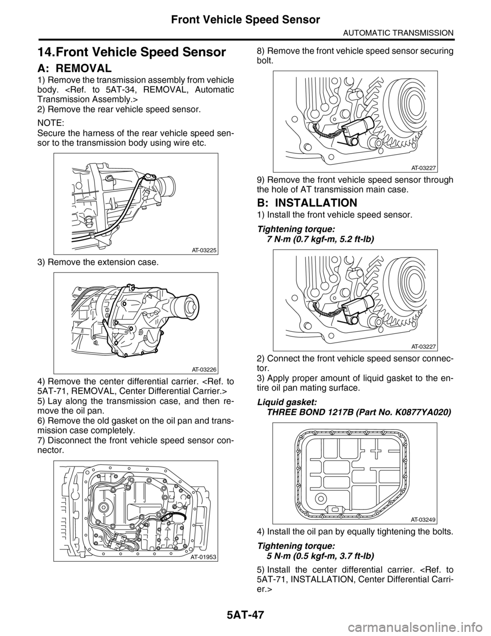
1) Remove the transmission assembly from vehicle
body.
Transmission Assembly.>
2) Remove the rear vehicle speed sensor.
NOTE:
Secure the harness of the rear vehicle speed sen-
sor to the transmission body using wire etc.
3) Remove the extension case.
4) Remove the center differential carrier.
5AT-71, REMOVAL, Center Differential Carrier.>
5) Lay along the transmission case, and then re-
move the oil pan.
6) Remove the old gasket on the oil pan and trans-
mission case completely.
7) Disconnect the front vehicle speed sensor con-
nector.
8) Remove the front vehicle speed sensor securing
bolt.
9) Remove the front vehicle speed sensor through
the hole of AT transmission main case.
B: INSTALLATION
1) Install the front vehicle speed sensor.
Tightening torque:
7 N·m (0.7 kgf-m, 5.2 ft-lb)
2) Connect the front vehicle speed sensor connec-
tor.
3) Apply proper amount of liquid gasket to the en-
tire oil pan mating surface.
Liquid gasket:
THREE BOND 1217B (Part No. K0877YA020)
4) Install the oil pan by equally tightening the bolts.
Tightening torque:
5 N·m (0.5 kgf-m, 3.7 ft-lb)
5) Install the center differential carrier.
5AT-71, INSTALLATION, Center Differential Carri-
er.>
AT-03225
AT-03226
AT-01953
AT-03227
AT-03227
AT-03249
Page 2064 of 2453
5AT-48
Front Vehicle Speed Sensor
AUTOMATIC TRANSMISSION
6) Install the extension case.
Tightening torque:
25 N·m (2.5 kgf-m, 18 ft-lb)
7) Install the rear vehicle speed sensor.
Tightening torque:
7 N·m (0.7 kgf-m, 5.2 ft-lb)
8) Install the transmission assembly to the vehicle.
Transmission Assembly.>
9) Pour ATF from the oil charge pipe.
26, REPLACEMENT, Automatic Transmission Flu-
id.>
10) Check the level and leaks of ATF.
26, INSPECTION, Automatic Transmission Fluid.>
AT-03226
AT-03225
Page 2066 of 2453
5AT-50
Rear Vehicle Speed Sensor
AUTOMATIC TRANSMISSION
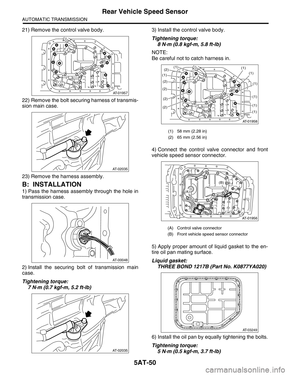
21) Remove the control valve body.
22) Remove the bolt securing harness of transmis-
sion main case.
23) Remove the harness assembly.
B: INSTALLATION
1) Pass the harness assembly through the hole in
transmission case.
2) Install the securing bolt of transmission main
case.
Tightening torque:
7 N·m (0.7 kgf-m, 5.2 ft-lb)
3) Install the control valve body.
Tightening torque:
8 N·m (0.8 kgf-m, 5.8 ft-lb)
NOTE:
Be careful not to catch harness in.
4) Connect the control valve connector and front
vehicle speed sensor connector.
5) Apply proper amount of liquid gasket to the en-
tire oil pan mating surface.
Liquid gasket:
THREE BOND 1217B (Part No. K0877YA020)
6) Install the oil pan by equally tightening the bolts.
Tightening torque:
5 N·m (0.5 kgf-m, 3.7 ft-lb)
AT-01957
AT-02035
AT-00048
AT-02035
(1) 58 mm (2.28 in)
(2) 65 mm (2.56 in)
(A) Control valve connector
(B) Front vehicle speed sensor connector
AT-01958
(1)(1)
(1)
(2)
(2)
(2)
(2)
(1)
(1)
(1)
(1)
(1)
(2)
AT-01956
(B)
(A)
AT-03249
Page 2067 of 2453
5AT-51
Rear Vehicle Speed Sensor
AUTOMATIC TRANSMISSION
7) Install the rear vehicle speed sensor and turbine
speed sensor 1, and then fasten the harness.
Tightening torque:
7 N·m (0.7 kgf-m, 5.2 ft-lb)
8) Install a new aluminum washer and oil cooler
pipe.
Tightening torque:
40 N·m (4.1 kgf-m, 29.5 ft-lb) (ATF inlet pipe)
45 N·m (4.6 kgf-m, 33.2 ft-lb) (ATF outlet pipe)
9) Install the oil charge pipe.
STALLATION, Oil Charge Pipe.>
10) Install the transmission rear crossmember bolt.
Tightening torque:
70 N·m (7.1 kgf-m, 51.6 ft-lb)
11) Install the propeller shaft.
STALLATION, Propeller Shaft.>
12) Install the heat shield cover.
13) Install the rear exhaust pipe and muffler.
to EX(H6DO)-7, INSTALLATION, Rear Exhaust
Pipe.>
Muffler.>
14) Lower the vehicle.
15) Install the transmission connector to the stay,
and then connect the connector.
16) Install the air intake chamber.
IN(H6DO)-6, INSTALLATION, Air Intake Cham-
ber.>
17) Pour ATF from the oil charge pipe.
5AT-26, REPLACEMENT, Automatic Transmis-
sion Fluid.>
18) Check the level and leaks of ATF.
26, INSPECTION, Automatic Transmission Fluid.>
Page 2068 of 2453
5AT-52
Turbine Speed Sensor 1
AUTOMATIC TRANSMISSION
16.Turbine Speed Sensor 1
A: REMOVAL
1) Remove the air intake chamber.
IN(H6DO)-6, REMOVAL, Air Intake Chamber.>
2) Lift-up the vehicle.
3) Disconnect the turbine speed sensor 1 connec-
tor.
4) Remove the turbine speed sensor 1.
B: INSTALLATION
1) Install the turbine speed sensor 1.
Tightening torque:
7 N·m (0.7 kgf-m, 5.2 ft-lb)
2) Connect the turbine speed sensor 1 connector.
3) Lower the vehicle.
4) Install the air intake chamber.
IN(H6DO)-6, INSTALLATION, Air Intake Cham-
ber.>
AT-01387
AT-01387
Page 2069 of 2453
5AT-53
Control Valve Body
AUTOMATIC TRANSMISSION
17.Control Valve Body
A: REMOVAL
1) Set the vehicle on a lift.
2) Disconnect the ground cable from battery.
3) Lift-up the vehicle.
4) Clean the transmission exterior.
5) Remove the ATF drain plug to drain ATF.
CAUTION:
Immediately after the vehicle has been running
or after idling for a long time, the ATF will be
hot. Be careful not to burn yourself.
6) Tighten the ATF drain plug.
NOTE:
Use a new gasket.
Tightening torque:
20 N·m (2.0 kgf-m, 14.8 ft-lb)
7) Remove the oil pan.
CAUTION:
Be sure to prevent the entering of dust and oth-
er foreign matters into oil pan.
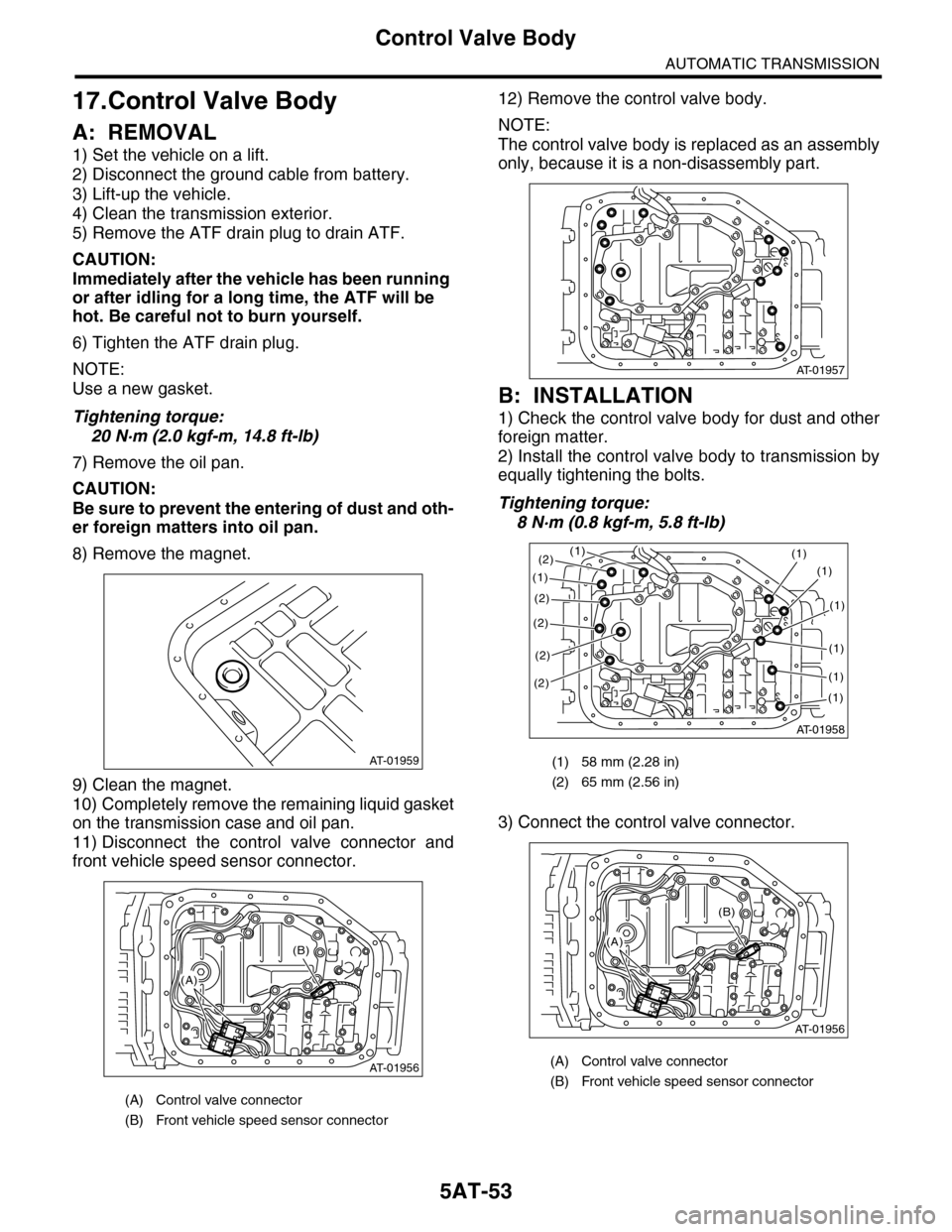
8) Remove the magnet.
9) Clean the magnet.
10) Completely remove the remaining liquid gasket
on the transmission case and oil pan.
11) Disconnect the control valve connector and
front vehicle speed sensor connector.
12) Remove the control valve body.
NOTE:
The control valve body is replaced as an assembly
only, because it is a non-disassembly part.
B: INSTALLATION
1) Check the control valve body for dust and other
foreign matter.
2) Install the control valve body to transmission by
equally tightening the bolts.
Tightening torque:
8 N·m (0.8 kgf-m, 5.8 ft-lb)
3) Connect the control valve connector.
(A) Control valve connector
(B) Front vehicle speed sensor connector
AT-01959
AT-01956
(B)
(A)
(1) 58 mm (2.28 in)
(2) 65 mm (2.56 in)
(A) Control valve connector
(B) Front vehicle speed sensor connector
AT-01957
AT-01958
(1)(1)
(1)
(2)
(2)
(2)
(2)
(1)
(1)
(1)
(1)
(1)
(2)
AT-01956
(B)
(A)
Page 2070 of 2453
5AT-54
Control Valve Body
AUTOMATIC TRANSMISSION
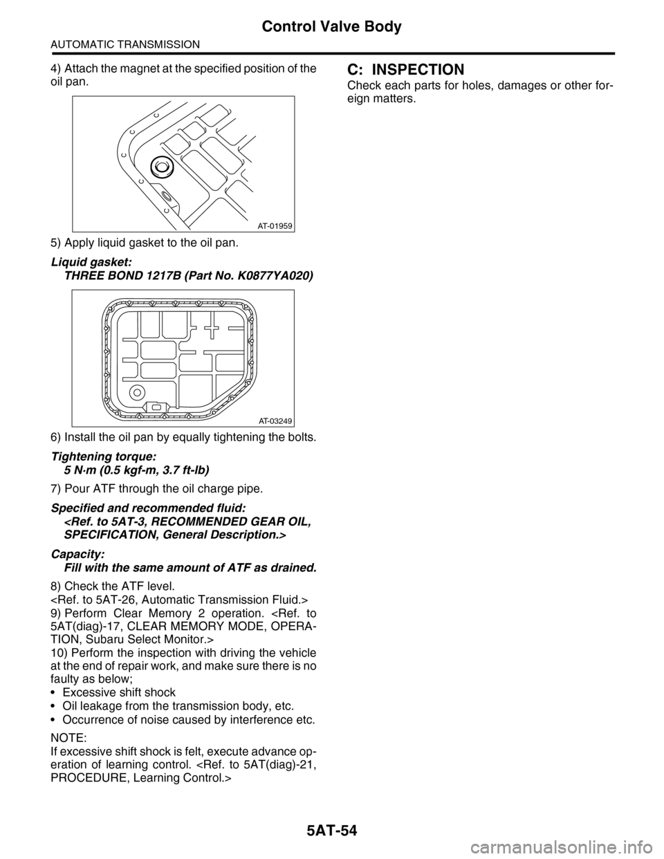
4) Attach the magnet at the specified position of the
oil pan.
5) Apply liquid gasket to the oil pan.
Liquid gasket:
THREE BOND 1217B (Part No. K0877YA020)
6) Install the oil pan by equally tightening the bolts.
Tightening torque:
5 N·m (0.5 kgf-m, 3.7 ft-lb)
7) Pour ATF through the oil charge pipe.
Specified and recommended fluid:
SPECIFICATION, General Description.>
Capacity:
Fill with the same amount of ATF as drained.
8) Check the ATF level.
9) Perform Clear Memory 2 operation.
5AT(diag)-17, CLEAR MEMORY MODE, OPERA-
TION, Subaru Select Monitor.>
10) Perform the inspection with driving the vehicle
at the end of repair work, and make sure there is no
faulty as below;
•Excessive shift shock
•Oil leakage from the transmission body, etc.
•Occurrence of noise caused by interference etc.
NOTE:
If excessive shift shock is felt, execute advance op-
eration of learning control.
PROCEDURE, Learning Control.>
C: INSPECTION
Check each parts for holes, damages or other for-
eign matters.
AT-01959
AT-03249
Page 2071 of 2453
5AT-55
ATF Filter
AUTOMATIC TRANSMISSION
18.ATF Filter
A: REMOVAL
1) Remove the front bumper.
MOVAL, Front Bumper.>
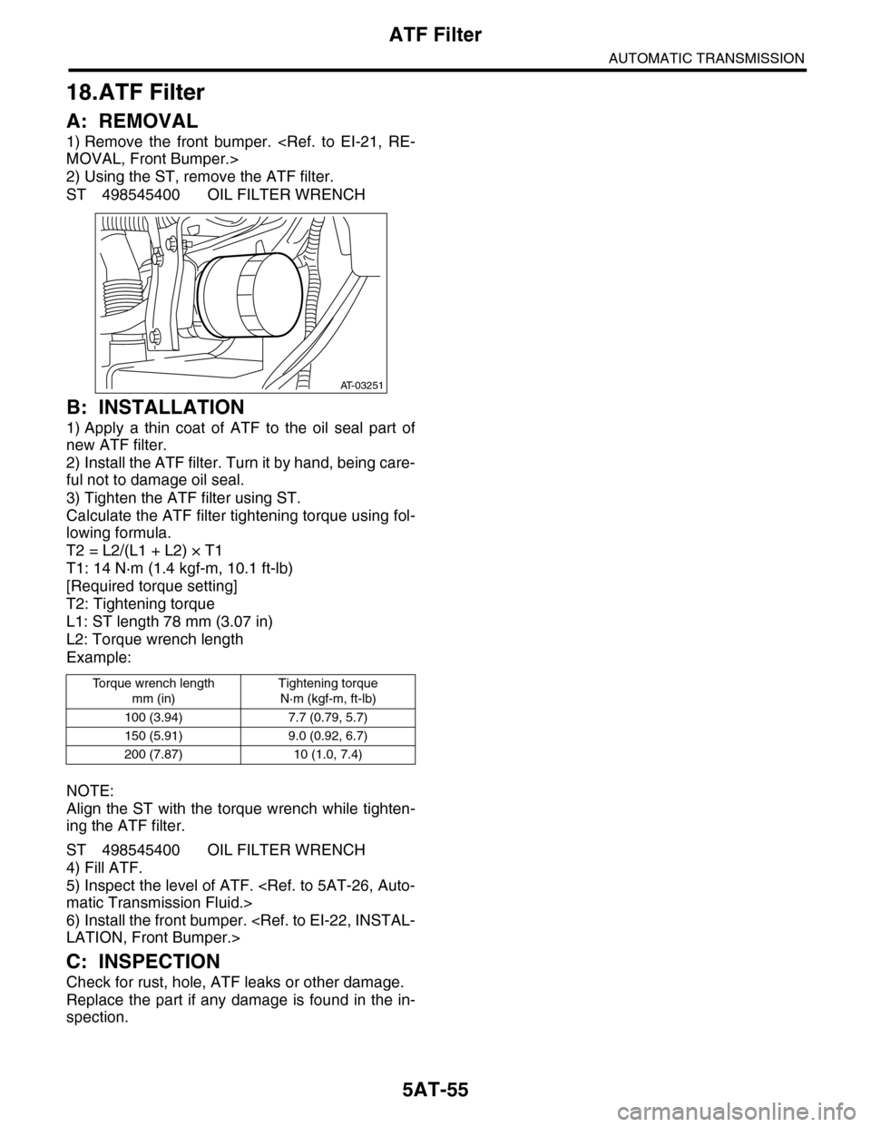
2) Using the ST, remove the ATF filter.
ST 498545400 OIL FILTER WRENCH
B: INSTALLATION
1) Apply a thin coat of ATF to the oil seal part of
new ATF filter.
2) Install the ATF filter. Turn it by hand, being care-
ful not to damage oil seal.
3) Tighten the ATF filter using ST.
Calculate the ATF filter tightening torque using fol-
lowing formula.
T2 = L2/(L1 + L2) × T1
T1: 14 N·m (1.4 kgf-m, 10.1 ft-lb)
[Required torque setting]
T2: Tightening torque
L1: ST length 78 mm (3.07 in)
L2: Torque wrench length
Example:
NOTE:
Align the ST with the torque wrench while tighten-
ing the ATF filter.
ST 498545400 OIL FILTER WRENCH
4) Fill ATF.
5) Inspect the level of ATF.
matic Transmission Fluid.>
6) Install the front bumper.
LATION, Front Bumper.>
C: INSPECTION
Check for rust, hole, ATF leaks or other damage.
Replace the part if any damage is found in the in-
spection.
To r q u e w r e n c h l e n g t h
mm (in)
Tightening torque
N·m (kgf-m, ft-lb)
100 (3.94) 7.7 (0.79, 5.7)
150 (5.91) 9.0 (0.92, 6.7)
200 (7.87) 10 (1.0, 7.4)
AT-03251