2009 SUBARU TRIBECA torque
[x] Cancel search: torquePage 2008 of 2453
PM-25
Suspension
PERIODIC MAINTENANCE SERVICES
4. WHEEL ALIGNMENT OF FRONT SUS-
PENSION
1) Check the alignment of front suspension to en-
sure that following items conform to standard val-
ues.
•Toe-in
•Camber
•Caster
•Steering angle
2) When the caster angle does not conform to ref-
erence obviously, visually inspect the following
components and replace deformed parts.
•Suspension components [Strut assembly, cross-
member, front arm, etc.]
•Parts connecting suspension and body
3) When the toe-in and camber are out of standard
value, adjust them so that they conform to standard
value.
4) When the right-and-left turning angles of tire are
out of standard, adjust to standard value.
5. WHEEL ALIGNMENT OF REAR SUS-
PENSION
1) Check the alignment of rear suspension to en-
sure that following items are within standard val-
ues.
•Toe-in
•Camber
•Thrust angle
2) When the camber angle does not conform to
standard value, visually inspect the following com-
ponents. If the deformation is observed, replace the
damaged parts.
•Suspension components [Shock absorber, rear
upper arm, front lateral link, rear lateral link, rear
trailing link, sub frame]
•Parts connecting suspension and body
3) When the toe-in and thrust angle are out of stan-
dard value, adjust them so that they conform to
standard value.
6. OIL LEAKAGE OF STRUT AND SHOCK
ABSORBER
Visually inspect the front strut and rear shock ab-
sorber for oil leakage. Replace the front strut and
rear shock absorber if oil leaks excessively.
7. TIGHTNESS OF BOLTS AND NUTS
Check the bolts and nuts for looseness. Retighten
the bolts and nuts to specified torque. If the self-
locking nuts and bolts are removed, replace them
with new ones.
•Front suspension
•Rear suspension
8. DAMAGE TO SUSPENSION PARTS
Check the following parts and the fastening portion
of the vehicle body for deformation or excessive
rusting which impairs the suspension. If necessary,
replace the damaged parts with new ones. If minor
rust formation, pitting, etc. are noted, remove the
rust and take rust prevention measure.
•Front suspension
•Front arm
•Crossmember
•Strut
•Rear suspension
•Upper arm
•Front lateral link
•Rear lateral link
•Rear trailing link
•Rear sub frame
•Shock absorber
•In the area where salt is sprayed to melt snow on
a road in winter, check suspension parts for dam-
age caused by rust every 12 months after lapse of
60 months. Take rust prevention measures as re-
quired.
Page 2012 of 2453
PM-29
Steering System (Power Steering)
PERIODIC MAINTENANCE SERVICES
21.Steering System (Power
Steering)
A: INSPECTION
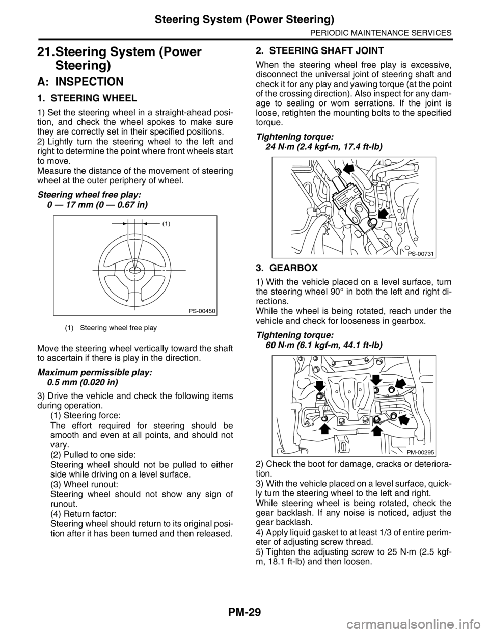
1. STEERING WHEEL
1) Set the steering wheel in a straight-ahead posi-
tion, and check the wheel spokes to make sure
they are correctly set in their specified positions.
2) Lightly turn the steering wheel to the left and
right to determine the point where front wheels start
to move.
Measure the distance of the movement of steering
wheel at the outer periphery of wheel.
Steering wheel free play:
0 — 17 mm (0 — 0.67 in)
Move the steering wheel vertically toward the shaft
to ascertain if there is play in the direction.
Maximum permissible play:
0.5 mm (0.020 in)
3) Drive the vehicle and check the following items
during operation.
(1) Steering force:
The effort required for steering should be
smooth and even at all points, and should not
vary.
(2) Pulled to one side:
Steering wheel should not be pulled to either
side while driving on a level surface.
(3) Wheel runout:
Steering wheel should not show any sign of
runout.
(4) Return factor:
Steering wheel should return to its original posi-
tion after it has been turned and then released.
2. STEERING SHAFT JOINT
When the steering wheel free play is excessive,
disconnect the universal joint of steering shaft and
check it for any play and yawing torque (at the point
of the crossing direction). Also inspect for any dam-
age to sealing or worn serrations. If the joint is
loose, retighten the mounting bolts to the specified
torque.
Tightening torque:
24 N·m (2.4 kgf-m, 17.4 ft-lb)
3. GEARBOX
1) With the vehicle placed on a level surface, turn
the steering wheel 90° in both the left and right di-
rections.
While the wheel is being rotated, reach under the
vehicle and check for looseness in gearbox.
Tightening torque:
60 N·m (6.1 kgf-m, 44.1 ft-lb)
2) Check the boot for damage, cracks or deteriora-
tion.
3) With the vehicle placed on a level surface, quick-
ly turn the steering wheel to the left and right.
While steering wheel is being rotated, check the
gear backlash. If any noise is noticed, adjust the
gear backlash.
4) Apply liquid gasket to at least 1/3 of entire perim-
eter of adjusting screw thread.
5) Tighten the adjusting screw to 25 N·m (2.5 kgf-
m, 18.1 ft-lb) and then loosen.
(1) Steering wheel free play
(1)
PS-00450
PS-00731
PM-00295
Page 2013 of 2453
PM-30
Steering System (Power Steering)
PERIODIC MAINTENANCE SERVICES
6) Tighten the adjusting screw to 3.9 N·m (0.40 kgf-
m, 2.9 ft-lb) and then loosen 20°.
7) Install the lock nut. While holding the adjusting
screw with wrench, tighten the lock nut using ST.
ST 926230000 SPANNER
Tightening torque (lock nut):
25 N·m (2.5 kgf-m, 18.1 ft-lb)
Hold the adjusting screw with wrench to prevent it
from turning while tightening the lock nut.
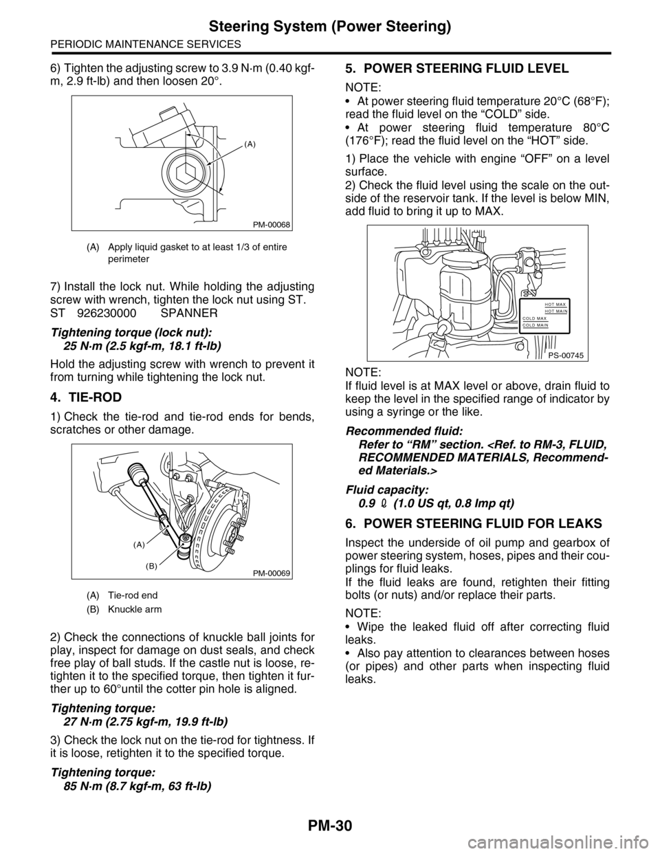
4. TIE-ROD
1) Check the tie-rod and tie-rod ends for bends,
scratches or other damage.
2) Check the connections of knuckle ball joints for
play, inspect for damage on dust seals, and check
free play of ball studs. If the castle nut is loose, re-
tighten it to the specified torque, then tighten it fur-
ther up to 60°until the cotter pin hole is aligned.
Tightening torque:
27 N·m (2.75 kgf-m, 19.9 ft-lb)
3) Check the lock nut on the tie-rod for tightness. If
it is loose, retighten it to the specified torque.
Tightening torque:
85 N·m (8.7 kgf-m, 63 ft-lb)
5. POWER STEERING FLUID LEVEL
NOTE:
•At power steering fluid temperature 20°C (68°F);
read the fluid level on the “COLD” side.
•At power steering fluid temperature 80°C
(176°F); read the fluid level on the “HOT” side.
1) Place the vehicle with engine “OFF” on a level
surface.
2) Check the fluid level using the scale on the out-
side of the reservoir tank. If the level is below MIN,
add fluid to bring it up to MAX.
NOTE:
If fluid level is at MAX level or above, drain fluid to
keep the level in the specified range of indicator by
using a syringe or the like.
Recommended fluid:
Refer to “RM” section.
ed Materials.>
Fluid capacity:
0.9 2 (1.0 US qt, 0.8 Imp qt)
6. POWER STEERING FLUID FOR LEAKS
Inspect the underside of oil pump and gearbox of
power steering system, hoses, pipes and their cou-
plings for fluid leaks.
If the fluid leaks are found, retighten their fitting
bolts (or nuts) and/or replace their parts.
NOTE:
•Wipe the leaked fluid off after correcting fluid
leaks.
•Also pay attention to clearances between hoses
(or pipes) and other parts when inspecting fluid
leaks.
(A) Apply liquid gasket to at least 1/3 of entire
perimeter
(A) Tie-rod end
(B) Knuckle arm
PM-00068
(A)
PM-00069
(A)
(B)
PS-00745
HOT MAXHOT MAINCOLD MAXCOLD MAIN
Page 2018 of 2453
5AT-2
General Description
AUTOMATIC TRANSMISSION
1. General Description
A: SPECIFICATION
1. TORQUE CONVERTER CLUTCH
2. OIL PUMP
3. TRANSMISSION CONTROL ELEMENT
4. TRANSMISSION GEAR RATIO
5. PLANETARY GEAR AND PLATE
6. SELECTOR POSITION
7. HYDRAULIC CONTROL AND LUBRICA-
TION
Ty p eSymmetric, 3 element, single stage,
2 phase torque converter
Stall torque ratio 1.9
Nominal diameter 250 mm (9.84 in)
Stall speed (at sea
level)2,300 — 2,800 rpm
One–way clutch Sprague type one-way clutch
Ty p e I n t e r n a l g e a r f i x e d d i s p l a c e m e n t p u m p
Driving method Driven by engine
Number of teethInner rotor 9
Outer rotor 10
Ty p e5-forward, 1-reverse,
double-row planetary gears
Multi–plate clutch 3 sets
Multi–plate brake 4 sets
One-way clutch
(sprague type)3 sets
1st 3.841
2nd 2.352
3rd 1.529
4th 1.000
5th 0.839
Rev. 2.764
Number of front internal gear teeth 102
Number of front carrier teeth 24
Number of front sun gear teeth 54
Number of mid internal gear teeth 78
Number of mid carrier teeth 18
Number of mid sun gear teeth 42
Number of rear internal gear teeth 98
Number of rear carrier teeth 18
Number of rear sun gear teeth 62
Number of front brake drive plates 2
Number of input clutch drive plates 5
Number of high & low reverse clutch
drive plates4
Number of direct clutch drive plates 5
Number of reverse brake drive plates 5
Number of forward brake drive plates 4
Number of low coast brake drive plates 3
P (Park)
Tr a n s m i s s i o n i s i n n e u t r a l , o u t p u t m e m -
ber is immovable, engine start is possi-
ble
R (Reverse) Transmission in reverse for backing
N (Neutral)Tr a n s m i s s i o n i s i n n e u t r a l a n d e n g i n e
start is possible
D (Drive)Automatic gear change
1st ←→ 2nd ←→ 3rd ←→ 4th ←→ 5th
Manual mode (+)Manual gear change
1st→ 2nd→ 3rd→ 4th→ 5th
Manual mode (–)Manual gear change
1st← 2nd← 3rd← 4th← 5th
Control method Wire cable type
Ty p e
Electronic/hydraulic control [5 forward
gear changes made by electronic sig-
nals of vehicle speed and accelerator
(throttle) opening]
Fluid
Specified fluid: SUBARU ATF (Part No.
K0140Y0700)
Recommended fluid: IDEMITSU ATF
HP
CASTROL TRANSMAX J
PENNZOIL QUAKERSTATE • PEN-
NZOIL ATF-J
NOTE:
Using of recommended fluid is permit-
ted only on the area where the speci-
fied is not available.
Fluid capacity
2(US qt, Imp qt)9.6 — 10.0 (10.1 — 10.6, 8.4 — 8.8)
Lubrication system Forced feed lubrication with oil pump
Page 2020 of 2453
5AT-4
General Description
AUTOMATIC TRANSMISSION
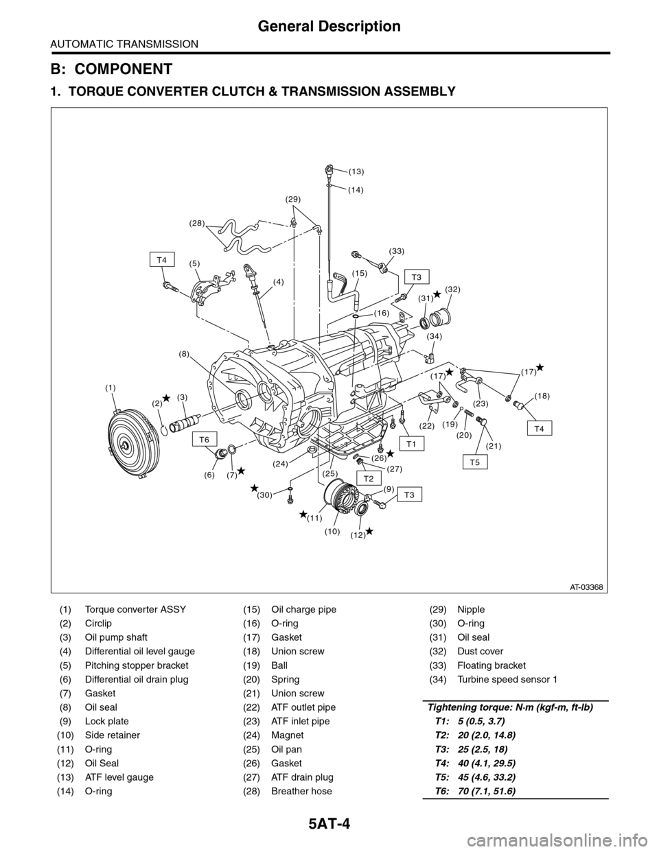
B: COMPONENT
1. TORQUE CONVERTER CLUTCH & TRANSMISSION ASSEMBLY
(1) Torque converter ASSY (15) Oil charge pipe (29) Nipple
(2) Circlip (16) O-ring (30) O-ring
(3) Oil pump shaft (17) Gasket (31) Oil seal
(4) Differential oil level gauge (18) Union screw (32) Dust cover
(5) Pitching stopper bracket (19) Ball (33) Floating bracket
(6) Differential oil drain plug (20) Spring (34) Turbine speed sensor 1
(7) Gasket (21) Union screw
(8) Oil seal (22) ATF outlet pipeTightening torque: N·m (kgf-m, ft-lb)
(9) Lock plate (23) ATF inlet pipeT1: 5 (0.5, 3.7)
(10) Side retainer (24) MagnetT2: 20 (2.0, 14.8)
(11) O-ring (25) Oil panT3: 25 (2.5, 18)
(12) Oil Seal (26) GasketT4: 40 (4.1, 29.5)
(13) ATF level gauge (27) ATF drain plugT5: 45 (4.6, 33.2)
(14) O-ring (28) Breather hoseT6: 70 (7.1, 51.6)
T6
T4
T3
T5
T1
T2
T4
T3
(12)
(11)
(7)(6)
(10)
(21)
(20)
(23)
(26)
(25)(24)(27)
(30)
(19)(22)
(18)
(17)
(34)
(32)
(16)
(15)
(14)
(13)
(28)
(4)
(5)
(1)
(2)(3)
(8)
(29)
(33)
(31)
(9)
(17)
AT-03368
Page 2025 of 2453
5AT-9
General Description
AUTOMATIC TRANSMISSION
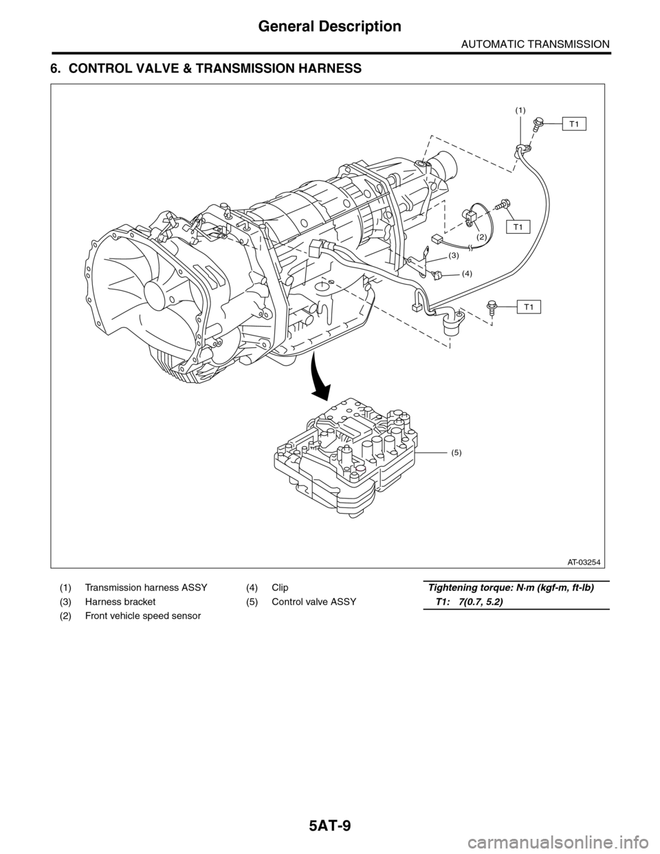
6. CONTROL VALVE & TRANSMISSION HARNESS
(1) Transmission harness ASSY (4) ClipTightening torque: N·m (kgf-m, ft-lb)
(3) Harness bracket (5) Control valve ASSYT1: 7(0.7, 5.2)
(2) Front vehicle speed sensor
(1)
(2)
(3)
(4)
(5)
T1
T1
T1
AT-03254
Page 2029 of 2453
5AT-13
General Description
AUTOMATIC TRANSMISSION
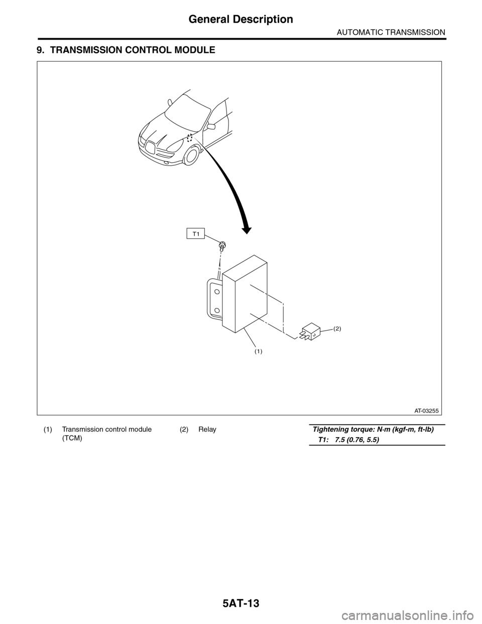
9. TRANSMISSION CONTROL MODULE
(1) Transmission control module
(TCM)
(2) RelayTightening torque: N·m (kgf-m, ft-lb)
T1: 7.5 (0.76, 5.5)
(2)
(1)
T1
AT-03255
Page 2030 of 2453
5AT-14
General Description
AUTOMATIC TRANSMISSION
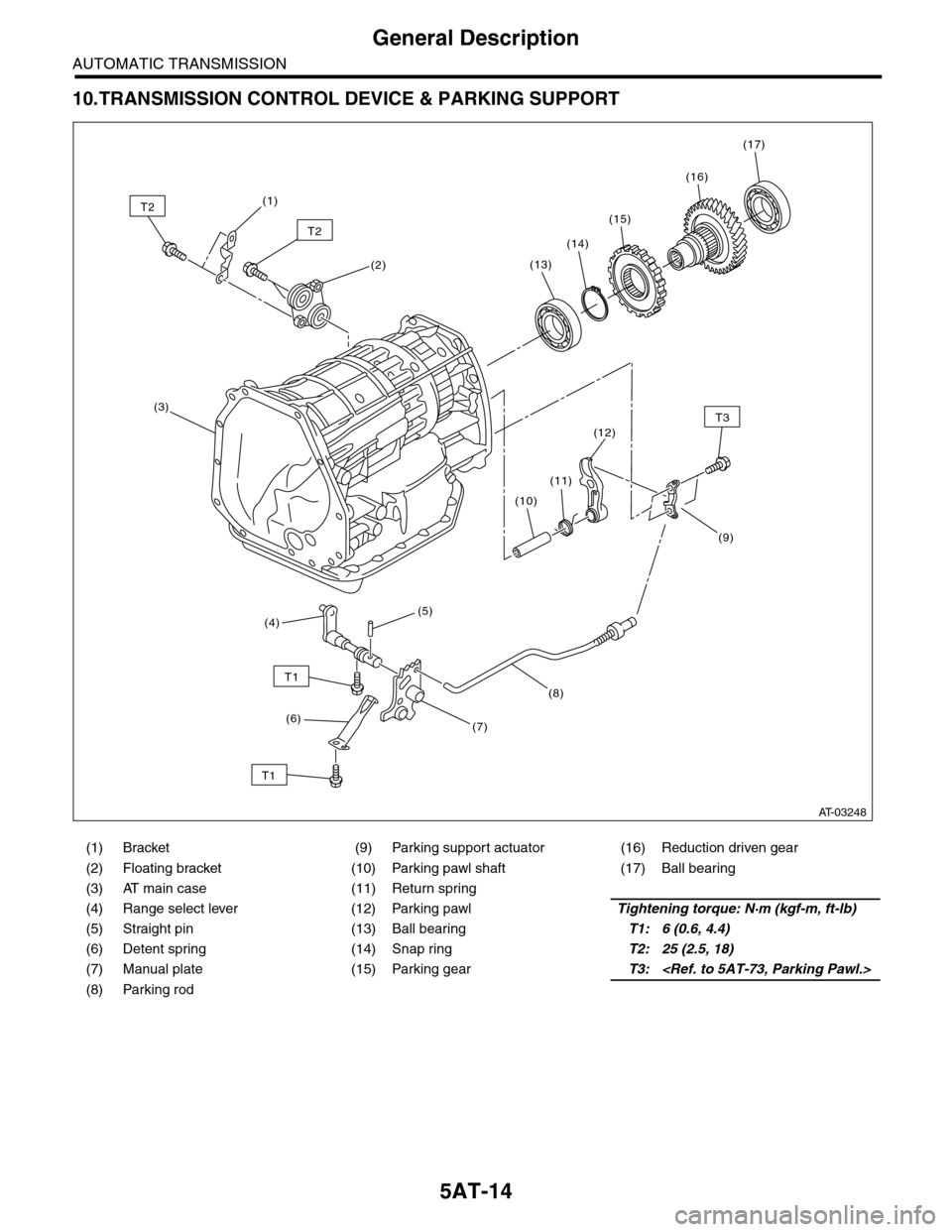
10.TRANSMISSION CONTROL DEVICE & PARKING SUPPORT
(1) Bracket (9) Parking support actuator (16) Reduction driven gear
(2) Floating bracket (10) Parking pawl shaft (17) Ball bearing
(3) AT main case (11) Return spring
(4) Range select lever (12) Parking pawlTightening torque: N·m (kgf-m, ft-lb)
(5) Straight pin (13) Ball bearingT1: 6 (0.6, 4.4)
(6) Detent spring (14) Snap ringT2: 25 (2.5, 18)
(7) Manual plate (15) Parking gearT3:
(8) Parking rod
T2
T2
T3
T1
T1
(1)
(2)
(3)
(10)
(11)
(8)
(7)
(5)(4)
(6)
(12)
(13)
(14)
(15)
(16)
(17)
(9)
AT-03248