Page 1958 of 2453
SP(H6DO)-3
Accelerator Pedal
SPEED CONTROL SYSTEMS
2. Accelerator Pedal
A: REMOVAL
1) Disconnect the ground cable from battery.
2) Disconnect the connector.
3) Remove the nut securing accelerator pedal as-
sembly.
B: INSTALLATION
Install in the reverse order of removal.
Tightening torque:
7.5 N·m (0.76 kgf-m, 5.5 ft-lb)
C: DISASSEMBLY
NOTE:
The accelerator pedal cannot be disassembled.
SP-02035
Page 1961 of 2453
SC(H6DO)-3
General Description
STARTING/CHARGING SYSTEMS
B: COMPONENT
1. STARTER
(1) Front bracket (12) Wave washer (23) Space ring
(2) Front bearing (13) Internal gear (24) Snap ring
(3) Plunger (14) Washer (25) End frame cover
(4) Snap ring (15) Shaft (26) Plunger spring
(5) Stopper (16) Planetary gear (27) Magnet switch
(6) Overrunning clutch (17) Armature plate
(7) Snap ring (18) YokeTightening torque: N·m (kgf-m, ft-lb)
(8) Washer (19) ArmatureT1: 1.4 (0.14, 1.03)
(9) Lever (20) Brush holder ASSYT2: 6 (0.6, 4.4)
(10) Oilless bearing (21) End frameT3: 7.5 (0.8, 5.5)
(11) Shock absorber bearing (22) Rear bearingT4: 10 (1.0, 7.4)
SC-02108
T3
T1
T2
(1)
(2)
T4
(4)(21)
(22)
(23)
(24)
(25)(5)(6)
(7)
(8)
(15)
(14)(13)
(12)(11)
(10)(9)
(3)
(26)
(27)
(16)(17)
(18)
(19)
(20)
Page 1962 of 2453
SC(H6DO)-4
General Description
STARTING/CHARGING SYSTEMS
2. GENERATOR
(1) Pulley nut (7) Bearing (13) Terminals
(2) Pulley (8) Stator coil
(3) Front cover (9) IC regulator with brushTightening torque: N·m (kgf-m, ft-lb)
(4) Ball bearing (10) BrushT1: 3.9 (0.4, 2.9)
(5) Bearing retainer (11) RectifierT2: 4.6 (0.47, 3.4)
(6) Rotor (12) Rear coverT3: 103 (10.5, 76)
Page 1963 of 2453
SC(H6DO)-5
General Description
STARTING/CHARGING SYSTEMS
C: CAUTION
•Wear work clothing, including a cap, protective
goggles and protective shoes during operation.
•Remove contamination including dirt and corro-
sion before removal, installation or disassembly.
•Keep the disassembled parts in order and pro-
tect them from dust and dirt.
•Before removal, installation or disassembly, be
sure to clarify the failure. Avoid unnecessary re-
moval, installation, disassembly and replacement.
•Be careful not to burn yourself, because each
part on the vehicle is hot after running.
•Be sure to tighten fasteners including bolts and
nuts to the specified torque.
•Place shop jacks or rigid racks at the specified
points.
•Before disconnecting connectors of sensors or
units, be sure to disconnect the ground cable from
battery.
Page 1964 of 2453

SC(H6DO)-6
Starter
STARTING/CHARGING SYSTEMS
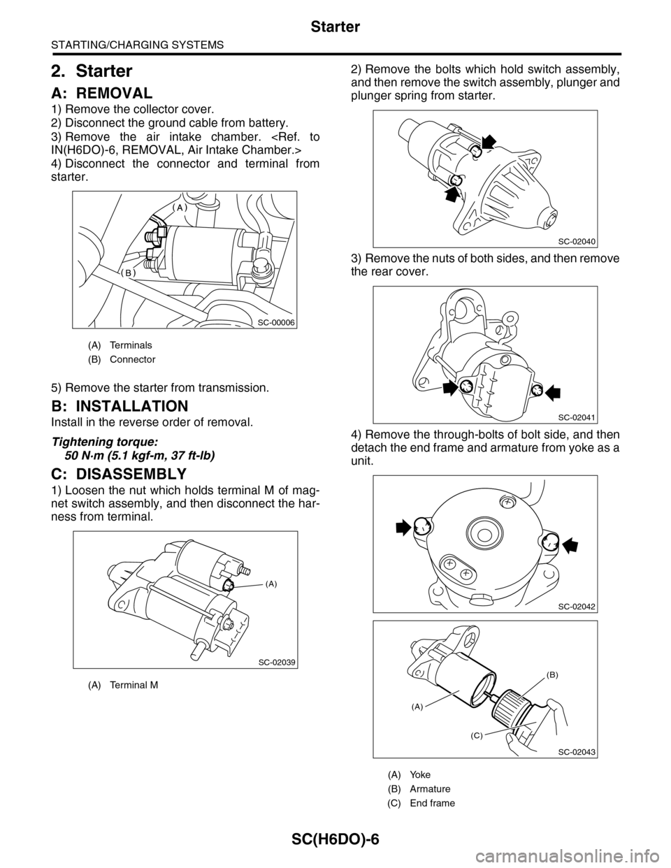
2. Starter
A: REMOVAL
1) Remove the collector cover.
2) Disconnect the ground cable from battery.
3) Remove the air intake chamber.
IN(H6DO)-6, REMOVAL, Air Intake Chamber.>
4) Disconnect the connector and terminal from
starter.
5) Remove the starter from transmission.
B: INSTALLATION
Install in the reverse order of removal.
Tightening torque:
50 N·m (5.1 kgf-m, 37 ft-lb)
C: DISASSEMBLY
1) Loosen the nut which holds terminal M of mag-
net switch assembly, and then disconnect the har-
ness from terminal.
2) Remove the bolts which hold switch assembly,
and then remove the switch assembly, plunger and
plunger spring from starter.
3) Remove the nuts of both sides, and then remove
the rear cover.
4) Remove the through-bolts of bolt side, and then
detach the end frame and armature from yoke as a
unit.
(A) Terminals
(B) Connector
(A) Terminal M
SC-00006
(A)
SC-02039
(A) Yoke
(B) Armature
(C) End frame
SC-02040
SC-02041
SC-02042
SC-02043
(A)
(C)
(B)
Page 1970 of 2453
SC(H6DO)-12
Starter
STARTING/CHARGING SYSTEMS
12) Assemble the brush assembly to end frame.
NOTE:
•Be careful not to allow grease to get on brush.
•Align the rubber seal part with end frame groove.
Tightening torque:
1.4 N·m (0.14 kgf-m, 1.03 ft-lb)
13) Install the armature to end frame.
NOTE:
•Apply grease to the rear bearing inner circumfer-
ence.
•Be careful not to allow grease to attach to com-
mutator.
Grease:
DENSO HL50
14) Set the space ring, then assemble the snap
ring.
NOTE:
•Use new snap rings.
•Check the dimension of (A) in the figure after as-
sembling snap ring. If it exceeds 5.0 mm (0.20 in),
assemble a new snap ring again.
15) Install the end frame cover.
SC-02048
SC-02047
(A) End frame cover
SC-02045
SC-02069
(A)
(A)
SC-02044
Page 1971 of 2453

SC(H6DO)-13
Starter
STARTING/CHARGING SYSTEMS
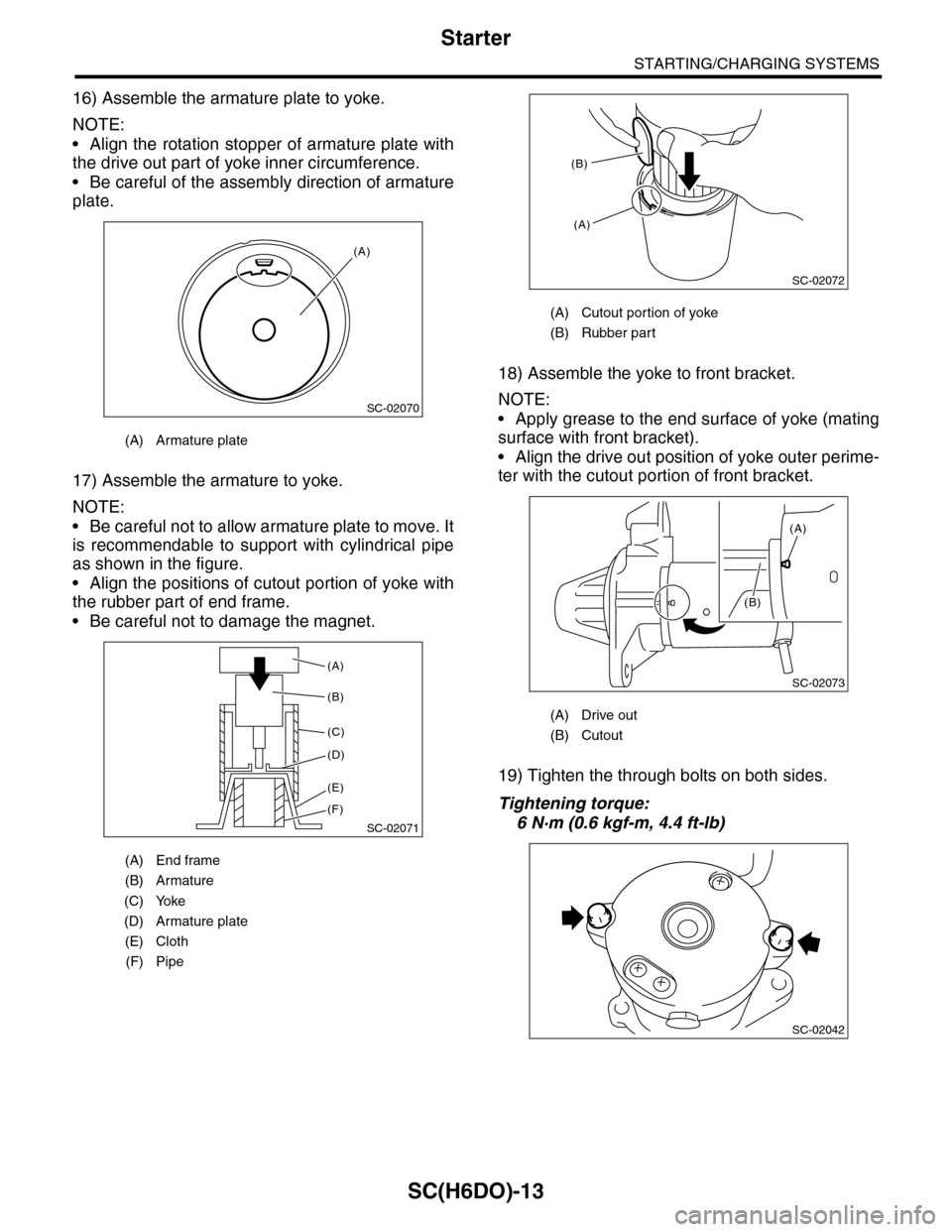
16) Assemble the armature plate to yoke.
NOTE:
•Align the rotation stopper of armature plate with
the drive out part of yoke inner circumference.
•Be careful of the assembly direction of armature
plate.
17) Assemble the armature to yoke.
NOTE:
•Be careful not to allow armature plate to move. It
is recommendable to support with cylindrical pipe
as shown in the figure.
•Align the positions of cutout portion of yoke with
the rubber part of end frame.
•Be careful not to damage the magnet.
18) Assemble the yoke to front bracket.
NOTE:
•Apply grease to the end surface of yoke (mating
surface with front bracket).
•Align the drive out position of yoke outer perime-
ter with the cutout portion of front bracket.
19) Tighten the through bolts on both sides.
Tightening torque:
6 N·m (0.6 kgf-m, 4.4 ft-lb)
(A) Armature plate
(A) End frame
(B) Armature
(C) Yoke
(D) Armature plate
(E) Cloth
(F) Pipe
SC-02070
(A)
SC-02071
(A)
(B)
(C)
(D)
(E)
(F)
(A) Cutout portion of yoke
(B) Rubber part
(A) Drive out
(B) Cutout
SC-02072
(B)
(A)
SC-02073
(A)
(B)
SC-02042
Page 1972 of 2453
SC(H6DO)-14
Starter
STARTING/CHARGING SYSTEMS
20) Install the rear cover.
21) Install the magnet switch assembly to front
bracket.
(1) Assemble the plunger hook to lever.
NOTE:
Apply grease to the plunger hook and sleeve inner
circumference.
Grease:
DENSO HL50
(2) Assemble the plunger spring and magnet
switch to front bracket.
NOTE:
Apply grease to the end surface of magnet switch
as shown in the figure.
Grease:
DENSO HL50
(3) Tighten the bolt.
Tightening torque:
7.5 N·m (0.8 kgf-m, 5.5 ft-lb)
22) Connect the harness to terminal M of magnet
switch assembly.
Tightening torque:
10 N·m (1.0 kgf-m, 7.4 ft-lb)
(A) Lever
(B) Plunger hook
(A) 5 mm
SC-02041
SC-02074
(A)
(B)
SC-02075
(A)
(A) Plunger
(B) Plunger spring
(C) Magnet switch
(A) Terminal M
SC-02076
(C)
(B)(A)
SC-02040
(A)
SC-02039