2009 SUBARU TRIBECA Back up
[x] Cancel search: Back upPage 1797 of 2453
GD(H6DO)-185
Diagnostic Trouble Code (DTC) Detecting Criteria
GENERAL DESCRIPTION
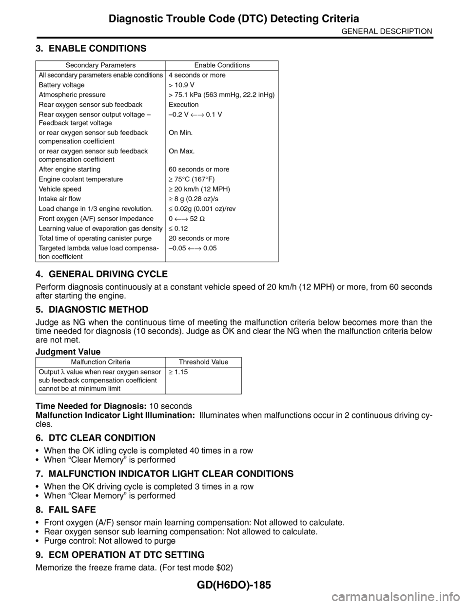
3. ENABLE CONDITIONS
4. GENERAL DRIVING CYCLE
Perform diagnosis continuously at a constant vehicle speed of 20 km/h (12 MPH) or more, from 60 seconds
after starting the engine.
5. DIAGNOSTIC METHOD
Judge as NG when the continuous time of meeting the malfunction criteria below becomes more than the
time needed for diagnosis (10 seconds). Judge as OK and clear the NG when the malfunction criteria below
are not met.
Time Needed for Diagnosis: 10 seconds
Malfunction Indicator Light Illumination: Illuminates when malfunctions occur in 2 continuous driving cy-
cles.
6. DTC CLEAR CONDITION
•When the OK idling cycle is completed 40 times in a row
•When “Clear Memory” is performed
7. MALFUNCTION INDICATOR LIGHT CLEAR CONDITIONS
•When the OK driving cycle is completed 3 times in a row
•When “Clear Memory” is performed
8. FAIL SAFE
•Front oxygen (A/F) sensor main learning compensation: Not allowed to calculate.
•Rear oxygen sensor sub learning compensation: Not allowed to calculate.
•Purge control: Not allowed to purge
9. ECM OPERATION AT DTC SETTING
Memorize the freeze frame data. (For test mode $02)
Secondary Parameters Enable Conditions
All secondary parameters enable conditions4 seconds or more
Battery voltage > 10.9 V
Atmospheric pressure > 75.1 kPa (563 mmHg, 22.2 inHg)
Rear oxygen sensor sub feedback Execution
Rear oxygen sensor output voltage –
Feedback target voltage
–0.2 V ←→ 0.1 V
or rear oxygen sensor sub feedback
compensation coefficient
On Min.
or rear oxygen sensor sub feedback
compensation coefficient
On Max.
After engine starting 60 seconds or more
Engine coolant temperature≥ 75°C (167°F)
Ve h i c l e s p e e d≥ 20 km/h (12 MPH)
Intake air flow≥ 8 g (0.28 oz)/s
Load change in 1/3 engine revolution.≤ 0.02g (0.001 oz)/rev
Fr o nt ox yg e n ( A / F) s en so r im pe d an c e 0 ←→ 52 Ω
Learning value of evaporation gas density≤ 0.12
To t a l t i m e o f o p e r a t i n g c a n i s t e r p u r g e 2 0 s e c o n d s o r m o r e
Ta r g e t e d l a m b d a v a l u e l o a d c o m p e n s a -
tion coefficient
–0.05 ←→ 0.05
Judgment Value
Malfunction Criteria Threshold Value
Output λ value when rear oxygen sensor
sub feedback compensation coefficient
cannot be at minimum limit
≥ 1.15
Page 1804 of 2453
GD(H6DO)-192
Diagnostic Trouble Code (DTC) Detecting Criteria
GENERAL DESCRIPTION
DM:DTC P1560 BACK-UP VOLTAGE CIRCUIT MALFUNCTION
1. OUTLINE OF DIAGNOSIS
Detect the open/short circuit of back-up power supply circuit.
Judge as NG when the backup power voltage is low.
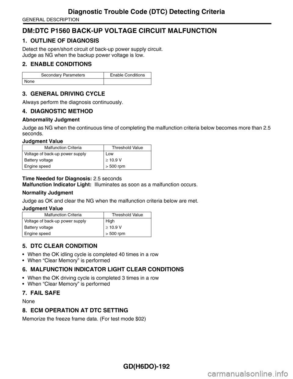
2. ENABLE CONDITIONS
3. GENERAL DRIVING CYCLE
Always perform the diagnosis continuously.
4. DIAGNOSTIC METHOD
Abnormality Judgment
Judge as NG when the continuous time of completing the malfunction criteria below becomes more than 2.5
seconds.
Time Needed for Diagnosis: 2.5 seconds
Malfunction Indicator Light: Illuminates as soon as a malfunction occurs.
Normality Judgment
Judge as OK and clear the NG when the malfunction criteria below are met.
5. DTC CLEAR CONDITION
•When the OK idling cycle is completed 40 times in a row
•When “Clear Memory” is performed
6. MALFUNCTION INDICATOR LIGHT CLEAR CONDITIONS
•When the OK driving cycle is completed 3 times in a row
•When “Clear Memory” is performed
7. FAIL SAFE
None
8. ECM OPERATION AT DTC SETTING
Memorize the freeze frame data. (For test mode $02)
Secondary Parameters Enable Conditions
None
Judgment Value
Malfunction Criteria Threshold Value
Vo l t a g e o f b a c k - u p p o w e r s u p p l y L o w
Battery voltage≥ 10.9 V
Engine speed > 500 rpm
Judgment Value
Malfunction Criteria Threshold Value
Vo l t a g e o f b a c k - u p p o w e r s u p p l y H i g h
Battery voltage≥ 10.9 V
Engine speed > 500 rpm
Page 1809 of 2453
GD(H6DO)-197
Diagnostic Trouble Code (DTC) Detecting Criteria
GENERAL DESCRIPTION
DY:DTC P2096 POST CATALYST FUEL TRIM SYSTEM TOO LEAN (BANK 1)
1. OUTLINE OF DIAGNOSIS
Detect the malfunction of fuel system from the size of the sub feedback learning value.
Control the sub feedback learning and judge as NG when the learning value is in the lean zone.
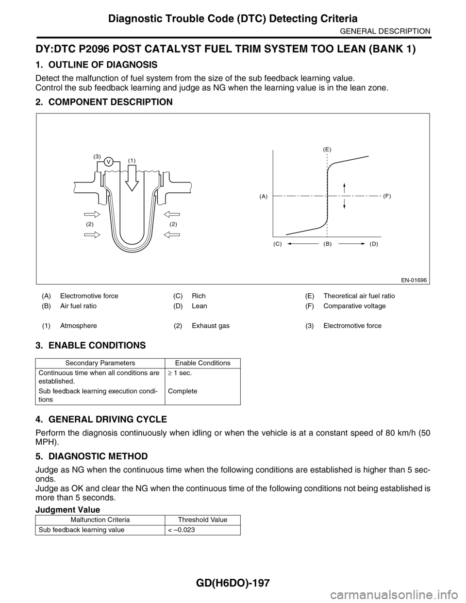
2. COMPONENT DESCRIPTION
3. ENABLE CONDITIONS
4. GENERAL DRIVING CYCLE
Perform the diagnosis continuously when idling or when the vehicle is at a constant speed of 80 km/h (50
MPH).
5. DIAGNOSTIC METHOD
Judge as NG when the continuous time when the following conditions are established is higher than 5 sec-
onds.
Judge as OK and clear the NG when the continuous time of the following conditions not being established is
more than 5 seconds.
(A) Electromotive force (C) Rich (E) Theoretical air fuel ratio
(B) Air fuel ratio (D) Lean (F) Comparative voltage
(1) Atmosphere (2) Exhaust gas (3) Electromotive force
Secondary Parameters Enable Conditions
Continuous time when all conditions are
established.
≥ 1 sec.
Sub feedback learning execution condi-
tions
Complete
Judgment Value
Malfunction Criteria Threshold Value
Sub feedback learning value < –0.023
EN-01696
(3)V(1)
(2) (2)
(E)
(F)
(C) (B) (D)
(A)
Page 1811 of 2453
GD(H6DO)-199
Diagnostic Trouble Code (DTC) Detecting Criteria
GENERAL DESCRIPTION
DZ:DTC P2097 POST CATALYST FUEL TRIM SYSTEM TOO RICH (BANK 1)
1. OUTLINE OF DIAGNOSIS
Detect the malfunction of fuel system from the size of the sub feedback learning value.
Sub feedback learning is being performed. When the learning value goes to the rich side, judge as NG.
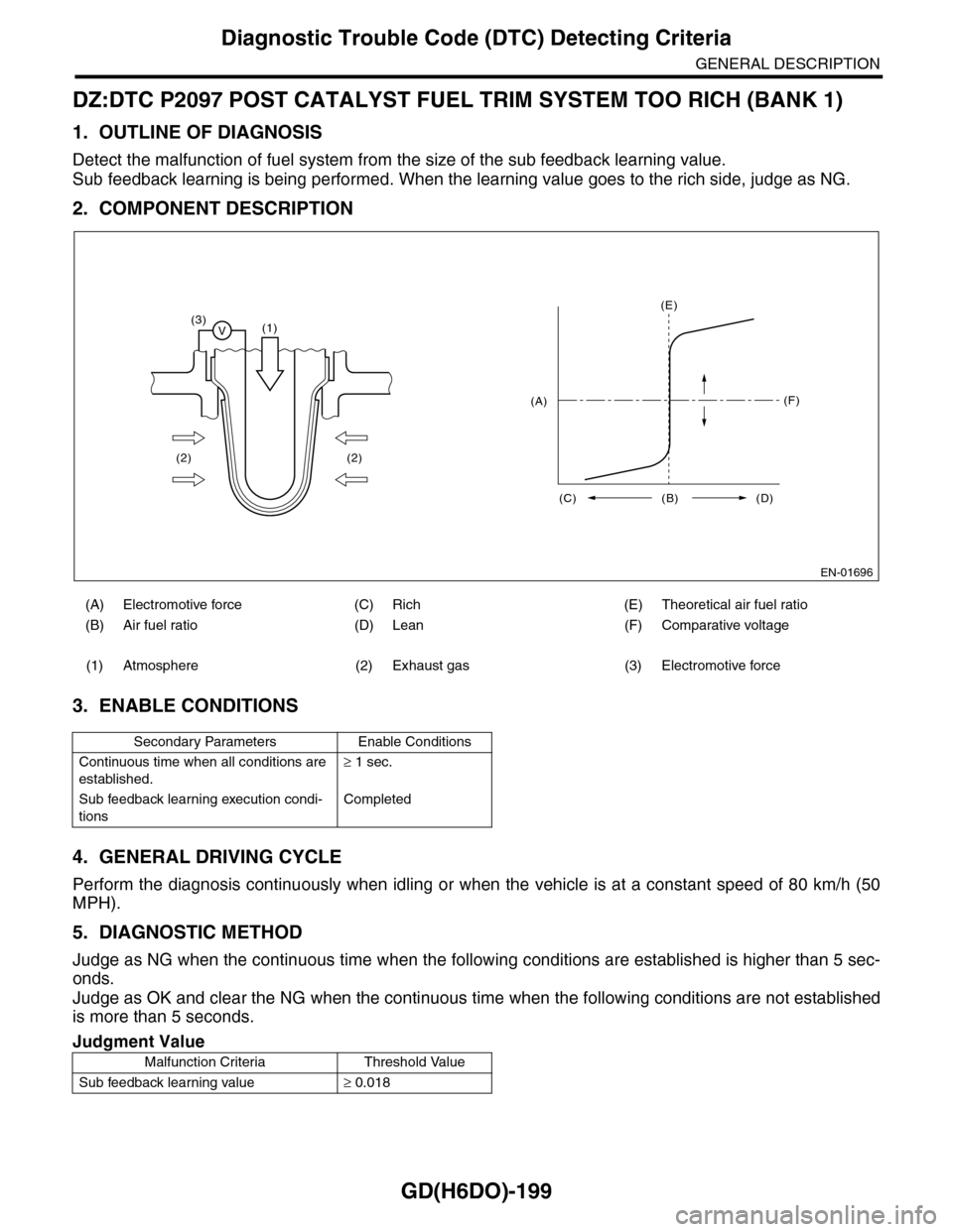
2. COMPONENT DESCRIPTION
3. ENABLE CONDITIONS
4. GENERAL DRIVING CYCLE
Perform the diagnosis continuously when idling or when the vehicle is at a constant speed of 80 km/h (50
MPH).
5. DIAGNOSTIC METHOD
Judge as NG when the continuous time when the following conditions are established is higher than 5 sec-
onds.
Judge as OK and clear the NG when the continuous time when the following conditions are not established
is more than 5 seconds.
(A) Electromotive force (C) Rich (E) Theoretical air fuel ratio
(B) Air fuel ratio (D) Lean (F) Comparative voltage
(1) Atmosphere (2) Exhaust gas (3) Electromotive force
Secondary Parameters Enable Conditions
Continuous time when all conditions are
established.
≥ 1 sec.
Sub feedback learning execution condi-
tions
Completed
Judgment Value
Malfunction Criteria Threshold Value
Sub feedback learning value≥ 0.018
EN-01696
(3)V(1)
(2) (2)
(E)
(F)
(C) (B) (D)
(A)
Page 1846 of 2453
IN(H6DO)-4
Air Cleaner Element
INTAKE (INDUCTION)
2. Air Cleaner Element
A: REMOVAL
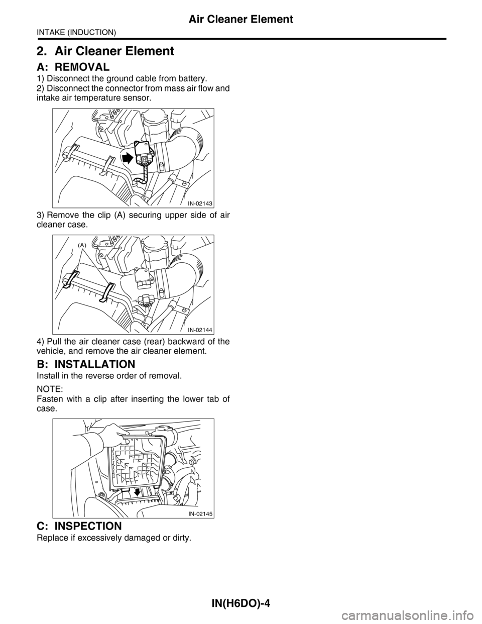
1) Disconnect the ground cable from battery.
2) Disconnect the connector from mass air flow and
intake air temperature sensor.
3) Remove the clip (A) securing upper side of air
cleaner case.
4) Pull the air cleaner case (rear) backward of the
vehicle, and remove the air cleaner element.
B: INSTALLATION
Install in the reverse order of removal.
NOTE:
Fasten with a clip after inserting the lower tab of
case.
C: INSPECTION
Replace if excessively damaged or dirty.
IN-02143
IN-02144
(A)
IN-02145
Page 1920 of 2453
ME(H6DO)-54
Camshaft
MECHANICAL
B: INSTALLATION
1) Apply engine oil to camshaft journals, and install
the camshaft.
2) Install the camshaft cap.
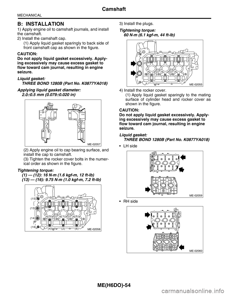
(1) Apply liquid gasket sparingly to back side of
front camshaft cap as shown in the figure.
CAUTION:
Do not apply liquid gasket excessively. Apply-
ing excessively may cause excess gasket to
flow toward cam journal, resulting in engine
seizure.
Liquid gasket:
THREE BOND 1280B (Part No. K0877YA018)
Applying liquid gasket diameter:
2.0±0.5 mm (0.079±0.020 in)
(2) Apply engine oil to cap bearing surface, and
install the cap to camshaft.
(3) Tighten the rocker cover bolts in the numer-
ical order as shown in the figure.
Tightening torque:
(1) — (12): 16 N·m (1.6 kgf-m, 12 ft-lb)
(13) — (16): 9.75 N·m (1.0 kgf-m, 7.2 ft-lb)
3) Install the plugs.
Tightening torque:
60 N·m (6.1 kgf-m, 44 ft-lb)
4) Install the rocker cover.
(1) Apply liquid gasket sparingly to the mating
surface of cylinder head and rocker cover as
shown in the figure.
CAUTION:
Do not apply liquid gasket excessively. Apply-
ing excessively may cause excess gasket to
flow toward cam journal, resulting in engine
seizure.
Liquid gasket:
THREE BOND 1280B (Part No. K0877YA018)
•LH side
•RH side
ME-02057
ME-02058
(1)
(2)
(8)
(7)(9)
(3)
(4)
(5)
(6)
(10)
(11)(13)
(14)
(15)
(16)
(12)
ME-02055
ME-02059
ME-02060
Page 1923 of 2453
ME(H6DO)-57
Cylinder Head
MECHANICAL
20.Cylinder Head
A: REMOVAL
1) Remove the crank pulley.
2) Remove the front chain cover.
3) Remove the timing chain assembly.
4) Remove the cam sprocket.
5) Remove the crank sprocket.
6) Remove the rear chain cover.
7) Remove the camshaft.
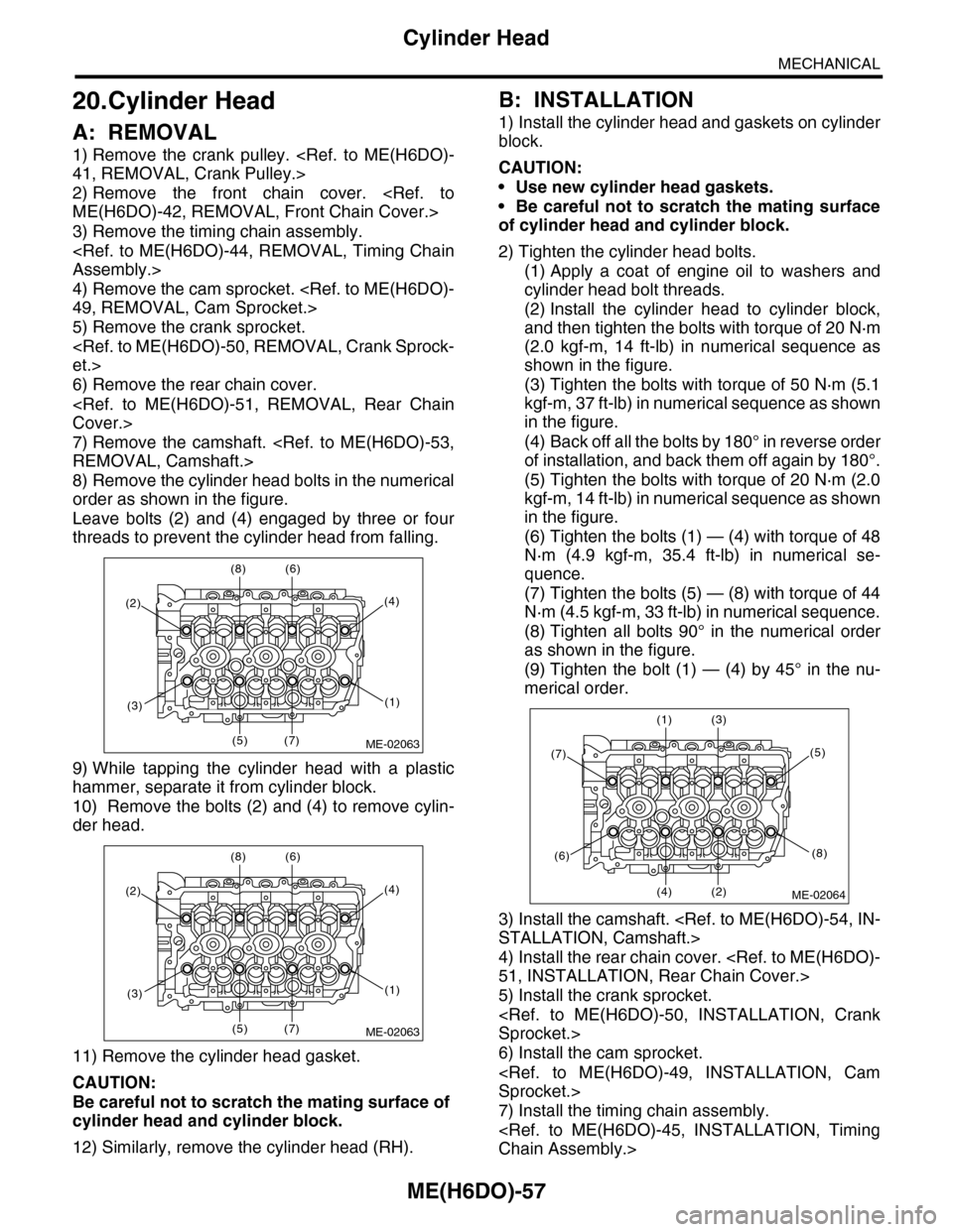
8) Remove the cylinder head bolts in the numerical
order as shown in the figure.
Leave bolts (2) and (4) engaged by three or four
threads to prevent the cylinder head from falling.
9) While tapping the cylinder head with a plastic
hammer, separate it from cylinder block.
10) Remove the bolts (2) and (4) to remove cylin-
der head.
11) Remove the cylinder head gasket.
CAUTION:
Be careful not to scratch the mating surface of
cylinder head and cylinder block.
12) Similarly, remove the cylinder head (RH).
B: INSTALLATION
1) Install the cylinder head and gaskets on cylinder
block.
CAUTION:
•Use new cylinder head gaskets.
•Be careful not to scratch the mating surface
of cylinder head and cylinder block.
2) Tighten the cylinder head bolts.
(1) Apply a coat of engine oil to washers and
cylinder head bolt threads.
(2) Install the cylinder head to cylinder block,
and then tighten the bolts with torque of 20 N·m
(2.0 kgf-m, 14 ft-lb) in numerical sequence as
shown in the figure.
(3) Tighten the bolts with torque of 50 N·m (5.1
kgf-m, 37 ft-lb) in numerical sequence as shown
in the figure.
(4) Back off all the bolts by 180° in reverse order
of installation, and back them off again by 180°.
(5) Tighten the bolts with torque of 20 N·m (2.0
kgf-m, 14 ft-lb) in numerical sequence as shown
in the figure.
(6) Tighten the bolts (1) — (4) with torque of 48
N·m (4.9 kgf-m, 35.4 ft-lb) in numerical se-
quence.
(7) Tighten the bolts (5) — (8) with torque of 44
N·m (4.5 kgf-m, 33 ft-lb) in numerical sequence.
(8) Tighten all bolts 90° in the numerical order
as shown in the figure.
(9) Tighten the bolt (1) — (4) by 45° in the nu-
merical order.
3) Install the camshaft.
4) Install the rear chain cover.
5) Install the crank sprocket.
6) Install the cam sprocket.
7) Install the timing chain assembly.
(2)
(8) (6)
(5) (7)
(4)
(1)(3)
ME-02063
(2)
(8) (6)
(5) (7)
(4)
(1)(3)
ME-02063
(7)
(1) (3)
(4) (2)
(5)
(8)(6)
ME-02064
Page 1926 of 2453
ME(H6DO)-60
Cylinder Head
MECHANICAL
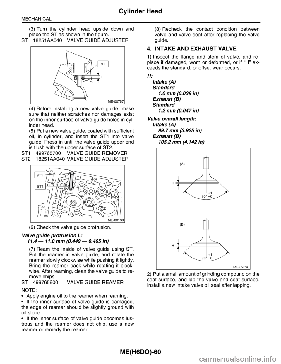
(3) Turn the cylinder head upside down and
place the ST as shown in the figure.
ST 18251AA040 VALVE GUIDE ADJUSTER
(4) Before installing a new valve guide, make
sure that neither scratches nor damages exist
on the inner surface of valve guide holes in cyl-
inder head.
(5) Put a new valve guide, coated with sufficient
oil, in cylinder, and insert the ST1 into valve
guide. Press in until the valve guide upper end
is flush with the upper surface of ST2.
ST1 499765700 VALVE GUIDE REMOVER
ST2 18251AA040 VALVE GUIDE ADJUSTER
(6) Check the valve guide protrusion.
Valve guide protrusion L:
11.4 — 11.8 mm (0.449 — 0.465 in)
(7) Ream the inside of valve guide using ST.
Put the reamer in valve guide, and rotate the
reamer slowly clockwise while pushing it lightly.
Bring the reamer back while rotating it clock-
wise. After reaming, clean the valve guide to re-
move chips.
ST 499765900 VALVE GUIDE REAMER
NOTE:
•Apply engine oil to the reamer when reaming.
•If the inner surface of valve guide is damaged,
the edge of reamer should be slightly ground with
oil stone.
•If the inner surface of valve guide becomes lus-
trous and the reamer does not chip, use a new
reamer or remedy the reamer.
(8) Recheck the contact condition between
valve and valve seat after replacing the valve
guide.
4. INTAKE AND EXHAUST VALVE
1) Inspect the flange and stem of valve, and re-
place if damaged, worn or deformed, or if “H” ex-
ceeds the standard, or offset wear occurs.
H:
Intake (A)
Standard
1.0 mm (0.039 in)
Exhaust (B)
Standard
1.2 mm (0.047 in)
Valve overall length:
Intake (A)
99.7 mm (3.925 in)
Exhaust (B)
105.2 mm (4.142 in)
2) Put a small amount of grinding compound on the
seat surface, and lap the valve and seat surface.
Install a new intake valve oil seal after lapping.
ME-00757
ST
L
ME-00130
ST1
ST2
ME-02096
H
H
(B)
(A)
90 0+1
90 0+1