2009 SUBARU TRIBECA Back up
[x] Cancel search: Back upPage 1149 of 2453
CO(H6DO)-30
Engine Cooling System Trouble in General
COOLING
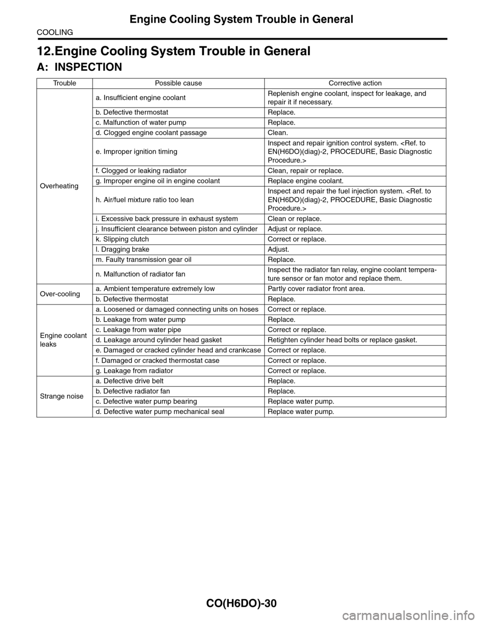
12.Engine Cooling System Trouble in General
A: INSPECTION
Tr o u b l e P o s s i b l e c a u s e C o r r e c t i v e a c t i o n
Overheating
a. Insufficient engine coolantReplenish engine coolant, inspect for leakage, and
repair it if necessary.
b. De fe c ti ve t he r mo st a t Rep la c e.
c. Malfunction of water pump Replace.
d. Clogged engine coolant passage Clean.
e. Improper ignition timing
Inspect and repair ignition control system.
Procedure.>
f. Clogged or leaking radiator Clean, repair or replace.
g. Improper engine oil in engine coolant Replace engine coolant.
h. Air/fuel mixture ratio too lean
Inspect and repair the fuel injection system.
Procedure.>
i. Excessive back pressure in exhaust system Clean or replace.
j. Insufficient clearance between piston and cylinder Adjust or replace.
k. Slipping clutch Correct or replace.
l. Dragging brake Adjust.
m. Faulty transmission gear oil Replace.
n. Malfunction of radiator fanInspect the radiator fan relay, engine coolant tempera-
ture sensor or fan motor and replace them.
Over-coolinga. Ambient temperature extremely low Partly cover radiator front area.
b. De fe c ti ve t he r mo st a t Rep la c e.
Engine coolant
leaks
a. Loosened or damaged connecting units on hoses Correct or replace.
b. L ea k ag e f r o m wat e r pu mp Rep la c e.
c. Leakage from water pipe Correct or replace.
d. Leakage around cylinder head gasket Retighten cylinder head bolts or replace gasket.
e. Damaged or cracked cylinder head and crankcase Correct or replace.
f. Damaged or cracked ther mostat case Correct or replace.
g. Leakage from radiator Correct or replace.
Strange noise
a. Defective drive belt Replace.
b. De fe c ti ve ra di a t or fan Rep la c e.
c. Defective water pump bearing Replace water pump.
d. Defective water pump mechanical seal Replace water pump.
Page 1165 of 2453
EN(H6DO)(diag)-4
Check List for Interview
ENGINE (DIAGNOSTICS)
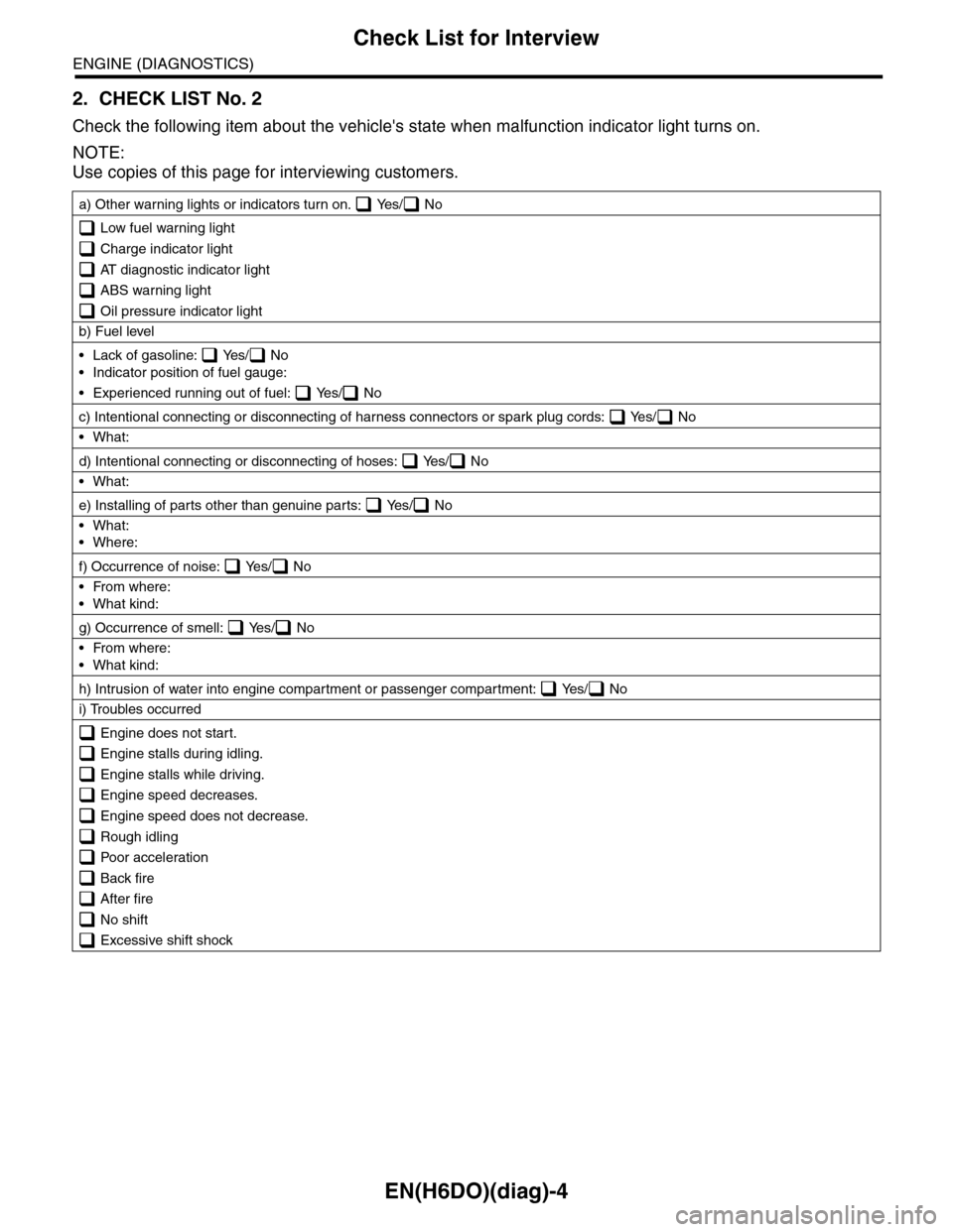
2. CHECK LIST No. 2
Check the following item about the vehicle's state when malfunction indicator light turns on.
NOTE:
Use copies of this page for interviewing customers.
a) Other warning lights or indicators turn on. Yes/ No
Low fuel warning light
Charge indicator light
AT diagnostic indicator light
ABS warning light
Oil pressure indicator light
b) Fuel level
•Lack of gasoline: Yes/ No
•Indicator position of fuel gauge:
•Experienced running out of fuel: Yes/ No
c) Intentional connecting or disconnecting of harness connectors or spark plug cords: Yes/ No
•What:
d) Intentional connecting or disconnecting of hoses: Yes/ No
•What:
e) Installing of parts other than genuine parts: Yes/ No
•What:
•Where:
f) Occurrence of noise: Yes/ No
•From where:
•What kind:
g) Occurrence of smell: Yes/ No
•From where:
•What kind:
h) Intrusion of water into engine compartment or passenger compartment: Yes/ No
i) Troubles occurred
Engine does not start.
Engine stalls during idling.
Engine stalls while driving.
Engine speed decreases.
Engine speed does not decrease.
Rough idling
Poor acceleration
Back fire
After fire
No shift
Excessive shift shock
Page 1178 of 2453
EN(H6DO)(diag)-17
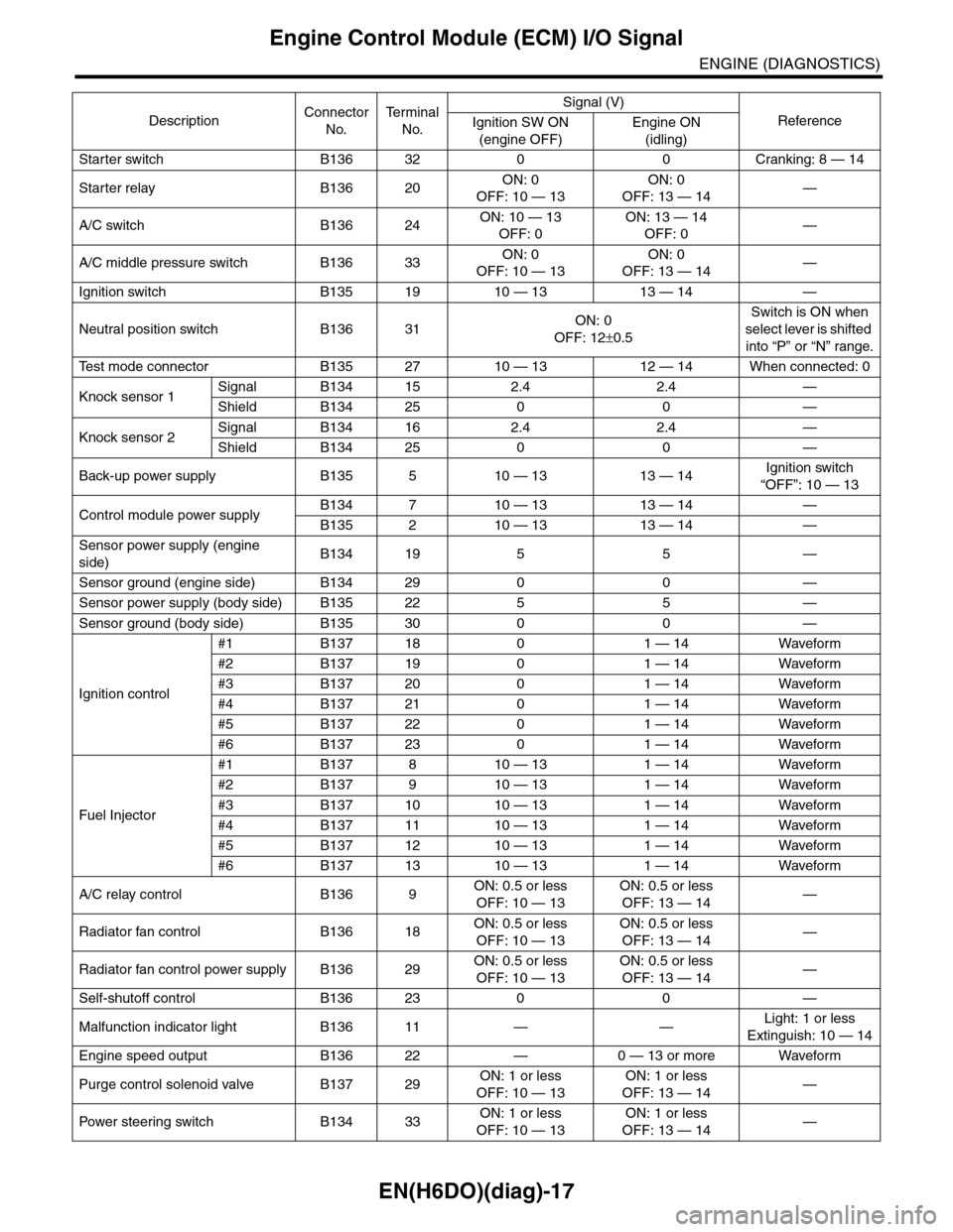
Engine Control Module (ECM) I/O Signal
ENGINE (DIAGNOSTICS)
Starter switch B136 32 0 0 Cranking: 8 — 14
Starter relay B136 20ON: 0
OFF: 10 — 13
ON: 0
OFF: 13 — 14—
A/C switch B136 24ON: 10 — 13
OFF: 0
ON: 13 — 14
OFF: 0—
A/C middle pressure switch B136 33ON: 0
OFF: 10 — 13
ON: 0
OFF: 13 — 14—
Ignition switch B135 19 10 — 13 13 — 14 —
Neutral position switch B136 31ON: 0
OFF: 12±0.5
Switch is ON when
select lever is shifted
into “P” or “N” range.
Te s t m o d e c o n n e c t o r B 1 3 5 2 7 1 0 — 1 3 1 2 — 1 4 W h e n c o n n e c t e d : 0
Knock sensor 1Signal B134 15 2.4 2.4 —
Shield B134 25 0 0 —
Knock sensor 2Signal B134 16 2.4 2.4 —
Shield B134 25 0 0 —
Back-up power supply B135 5 10 — 13 13 — 14Ignition switch
“OFF”: 10 — 13
Control module power supplyB134 7 10 — 13 13 — 14 —
B135 2 10 — 13 13 — 14 —
Sensor power supply (engine
side)B134 19 5 5 —
Sensor ground (engine side) B134 29 0 0 —
Sensor power supply (body side) B135 22 5 5 —
Sensor ground (body side) B135 30 0 0 —
Ignition control
#1 B137 18 0 1 — 14 Waveform
#2 B137 19 0 1 — 14 Waveform
#3 B137 20 0 1 — 14 Waveform
#4 B137 21 0 1 — 14 Waveform
#5 B137 22 0 1 — 14 Waveform
#6 B137 23 0 1 — 14 Waveform
Fuel Injector
#1 B137 8 10 — 13 1 — 14 Waveform
#2 B137 9 10 — 13 1 — 14 Waveform
#3 B137 10 10 — 13 1 — 14 Waveform
#4 B137 11 10 — 13 1 — 14 Waveform
#5 B137 12 10 — 13 1 — 14 Waveform
#6 B137 13 10 — 13 1 — 14 Waveform
A/C relay control B136 9ON: 0.5 or less
OFF: 10 — 13
ON: 0.5 or less
OFF: 13 — 14—
Radiator fan control B136 18ON: 0.5 or less
OFF: 10 — 13
ON: 0.5 or less
OFF: 13 — 14—
Radiator fan control power supply B136 29ON: 0.5 or less
OFF: 10 — 13
ON: 0.5 or less
OFF: 13 — 14—
Self-shutoff control B136 23 0 0 —
Malfunction indicator light B136 11 — —Light: 1 or less
Extinguish: 10 — 14
Engine speed output B136 22 — 0 — 13 or more Waveform
Purge control solenoid valve B137 29ON: 1 or less
OFF: 10 — 13
ON: 1 or less
OFF: 13 — 14—
Pow er s te e r in g sw it c h B 1 3 4 33ON: 1 or less
OFF: 10 — 13
ON: 1 or less
OFF: 13 — 14—
DescriptionConnector
No.
Te r m i n a l
No.
Signal (V)
ReferenceIgnition SW ON
(engine OFF)
Engine ON
(idling)
Page 1197 of 2453
EN(H6DO)(diag)-36
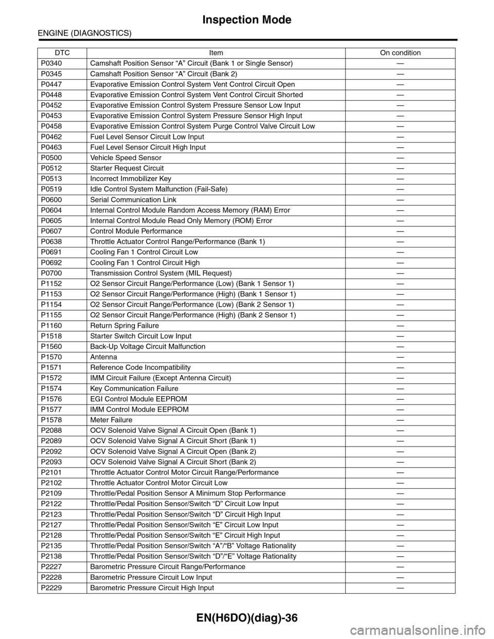
Inspection Mode
ENGINE (DIAGNOSTICS)
P0340 Camshaft Position Sensor “A” Circuit (Bank 1 or Single Sensor) —
P0345 Camshaft Position Sensor “A” Circuit (Bank 2) —
P0447 Evaporative Emission Control System Vent Control Circuit Open —
P0448 Evaporative Emission Control System Vent Control Circuit Shorted —
P0452 Evaporative Emission Control System Pressure Sensor Low Input —
P0453 Evaporative Emission Control System Pressure Sensor High Input —
P0458 Evaporative Emission Control System Purge Control Valve Circuit Low —
P0462 Fuel Level Sensor Circuit Low Input —
P0463 Fuel Level Sensor Circuit High Input —
P0500 Vehicle Speed Sensor—
P0512 Starter Request Circuit—
P0513 Incorrect Immobilizer Key —
P0519 Idle Control System Malfunction (Fail-Safe) —
P0600 Serial Communication Link —
P0604 Internal Control Module Random Access Memory (RAM) Error —
P0605 Internal Control Module Read Only Memory (ROM) Error —
P0607 Control Module Performance —
P0638 Throttle Actuator Control Range/Performance (Bank 1) —
P0691 Cooling Fan 1 Control Circuit Low —
P0692 Cooling Fan 1 Control Circuit High —
P0700 Transmission Control System (MIL Request) —
P1152 O2 Sensor Circuit Range/Performance (Low) (Bank 1 Sensor 1) —
P1153 O2 Sensor Circuit Range/Performance (High) (Bank 1 Sensor 1) —
P1154 O2 Sensor Circuit Range/Performance (Low) (Bank 2 Sensor 1) —
P1155 O2 Sensor Circuit Range/Performance (High) (Bank 2 Sensor 1) —
P1160 Return Spring Failure—
P1518 Starter Switch Circuit Low Input —
P1560 Back-Up Voltage Circuit Malfunction —
P1570 Antenna—
P1571 Reference Code Incompatibility —
P1572 IMM Circuit Failure (Except Antenna Circuit) —
P1574 Key Communication Failure —
P1576 EGI Control Module EEPROM —
P1577 IMM Control Module EEPROM —
P1578 Meter Failure—
P2088 OCV Solenoid Valve Signal A Circuit Open (Bank 1) —
P2089 OCV Solenoid Valve Signal A Circuit Short (Bank 1) —
P2092 OCV Solenoid Valve Signal A Circuit Open (Bank 2) —
P2093 OCV Solenoid Valve Signal A Circuit Short (Bank 2) —
P2101 Throttle Actuator Control Motor Circuit Range/Performance —
P2102 Throttle Actuator Control Motor Circuit Low —
P2109 Throttle/Pedal Position Sensor A Minimum Stop Performance —
P2122 Throttle/Pedal Position Sensor/Switch “D” Circuit Low Input —
P2123 Throttle/Pedal Position Sensor/Switch “D” Circuit High Input —
P2127 Throttle/Pedal Position Sensor/Switch “E” Circuit Low Input —
P2128 Throttle/Pedal Position Sensor/Switch “E” Circuit High Input —
P2135 Throttle/Pedal Position Sensor/Switch “A”/“B” Voltage Rationality —
P2138 Throttle/Pedal Position Sensor/Switch “D”/“E” Voltage Rationality —
P2227 Barometric Pressure Circuit Range/Performance —
P2228 Barometric Pressure Circuit Low Input —
P2229 Barometric Pressure Circuit High Input —
DTC Item On condition
Page 1235 of 2453
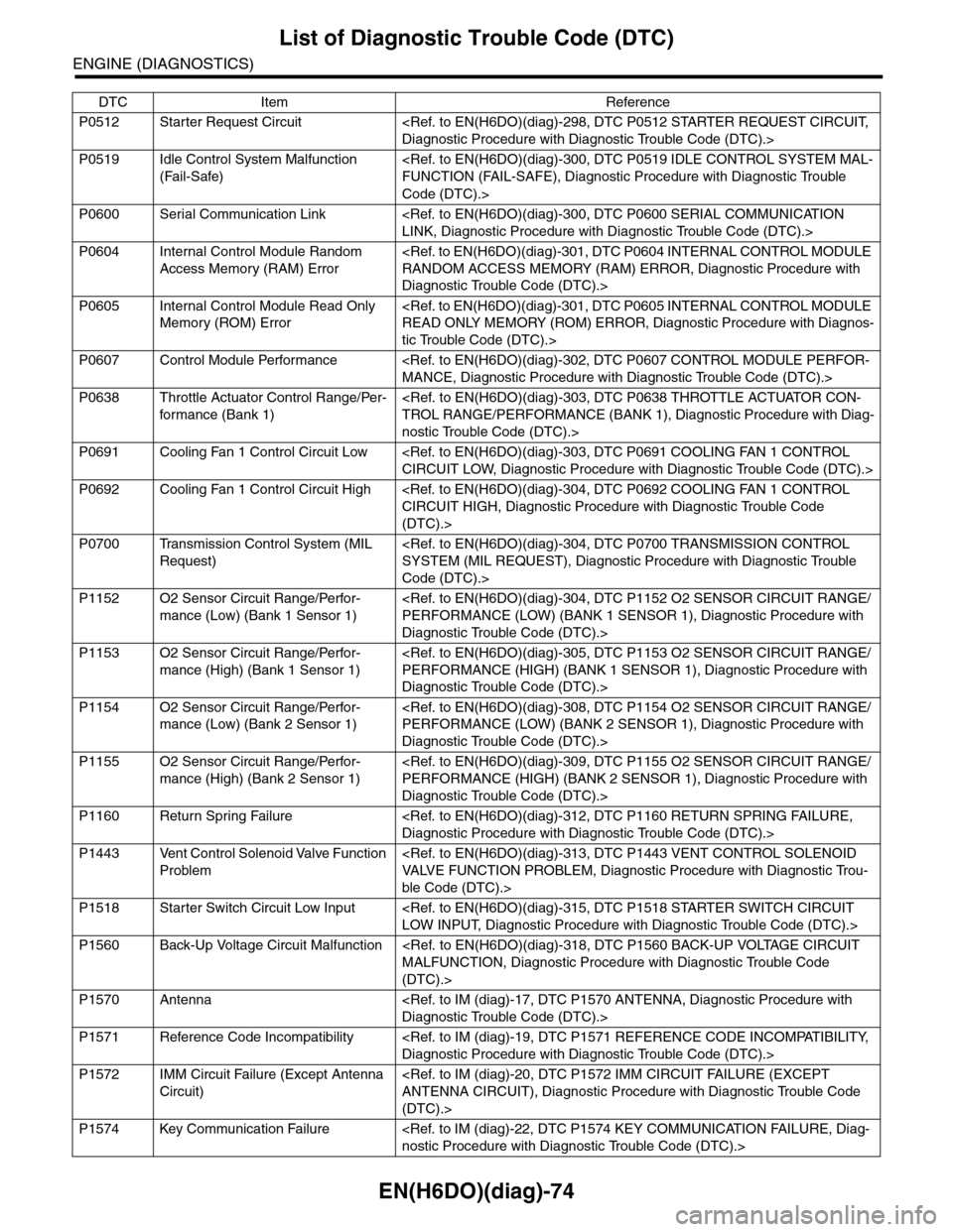
EN(H6DO)(diag)-74
List of Diagnostic Trouble Code (DTC)
ENGINE (DIAGNOSTICS)
P0512 Starter Request Circuit
P0519 Idle Control System Malfunction
(Fail-Safe)
Code (DTC).>
P0600 Serial Communication Link
P0604 Internal Control Module Random
Access Memory (RAM) Error
Diagnostic Trouble Code (DTC).>
P0605 Internal Control Module Read Only
Memory (ROM) Error
tic Trouble Code (DTC).>
P0607 Control Module Performance
P0638 Throttle Actuator Control Range/Per-
for mance (Bank 1)
nostic Trouble Code (DTC).>
P0691 Cooling Fan 1 Control Circuit Low
P0692 Cooling Fan 1 Control Circuit High
(DTC).>
P0700 Transmission Control System (MIL
Request)
Code (DTC).>
P1152 O2 Sensor Circuit Range/Perfor-
mance (Low) (Bank 1 Sensor 1)
Diagnostic Trouble Code (DTC).>
P1153 O2 Sensor Circuit Range/Perfor-
mance (High) (Bank 1 Sensor 1)
Diagnostic Trouble Code (DTC).>
P1154 O2 Sensor Circuit Range/Perfor-
mance (Low) (Bank 2 Sensor 1)
Diagnostic Trouble Code (DTC).>
P1155 O2 Sensor Circuit Range/Perfor-
mance (High) (Bank 2 Sensor 1)
Diagnostic Trouble Code (DTC).>
P1160 Return Spring Failure
P1443 Vent Control Solenoid Valve Function
Problem
ble Code (DTC).>
P1518 Starter Switch Circuit Low Input
P1560 Back-Up Voltage Circuit Malfunction
(DTC).>
P1570 Antenna
P1571 Reference Code Incompatibility
P1572 IMM Circuit Failure (Except Antenna
Circuit)
(DTC).>
P1574 Key Communication Failure
DTC Item Reference
Page 1479 of 2453
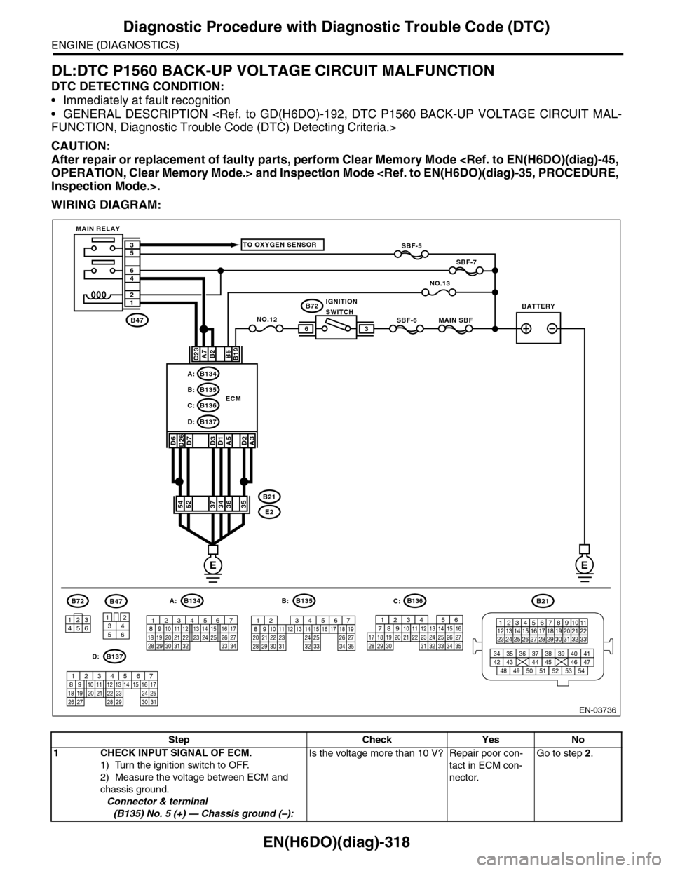
EN(H6DO)(diag)-318
Diagnostic Procedure with Diagnostic Trouble Code (DTC)
ENGINE (DIAGNOSTICS)
DL:DTC P1560 BACK-UP VOLTAGE CIRCUIT MALFUNCTION
DTC DETECTING CONDITION:
•Immediately at fault recognition
•GENERAL DESCRIPTION
CAUTION:
After repair or replacement of faulty parts, perform Clear Memory Mode
WIRING DIAGRAM:
EN-03736
SBF-6MAIN SBF
SBF-7
B72
B2A7C23
D7D3D1A5
B5B19
NO.12B47
E2
B21
12
46
53
ECM
EE
36
B134A:
D:B137
B135B:
B136C:
A3
52373634
3412
56
B47
TO OXYGEN SENSOR
NO.13
D2
35
B21
123412131415567816171819910 1120212223 24 25 2627 28 29 3031 32 33
3534 37363938 41404342 4445 47464948 51505352 54
B72
134562
B134
56 7821943102422 23 2511 12 13 14 1526 2728
16 1718 19 20 2133 34293230 31
A:B135
567821943102422 23 2511 12 13 14 1526 2728
16 17 18 1920 2129 30 31 32 33 34 35
B:
B137
5678219431022 2311 12 13 14 1524 2526
16 1718 19 20 2127 28 29 30 31
D:
SBF-5
D6D26
54
MAIN RELAY
BATTERYIGNITIONSWITCH
B136
16101112131415252430
9871718192028212223293231
123456
2726333435
C:
Step Check Yes No
1CHECK INPUT SIGNAL OF ECM.
1) Turn the ignition switch to OFF.
2) Measure the voltage between ECM and
chassis ground.
Connector & terminal
(B135) No. 5 (+) — Chassis ground (–):
Is the voltage more than 10 V? Repair poor con-
tact in ECM con-
nector.
Go to step 2.
Page 1619 of 2453
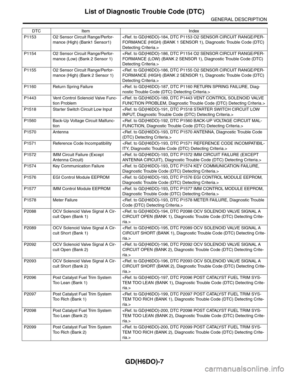
GD(H6DO)-7
List of Diagnostic Trouble Code (DTC)
GENERAL DESCRIPTION
P1153 O2 Sensor Circuit Range/Perfor-
mance (High) (Bank1 Sensor1)
Detecting Criteria.>
P1154 O2 Sensor Circuit Range/Perfor-
mance (Low) (Bank 2 Sensor 1)
Detecting Criteria.>
P1155 O2 Sensor Circuit Range/Perfor-
mance (High) (Bank 2 Sensor 1)
Detecting Criteria.>
P1160 Return Spring Failure
P1443 Vent Control Solenoid Valve Func-
tion Problem
P1518 Starter Switch Circuit Low Input
P1560 Back-Up Voltage Circuit Malfunc-
tion
P1570 Antenna
P1571 Reference Code Incompatibility
P1572 IMM Circuit Failure (Except
Antenna Circuit)
P1574 Key Communication Failure
P1576 EGI Control Module EEPROM
P1577 IMM Control Module EEPROM
P1578 Meter Failure
P2088 OCV Solenoid Valve Signal A Cir-
cuit Open (Bank 1)
ria.>
P2089 OCV Solenoid Valve Signal A Cir-
cuit Short (Bank 1)
ria.>
P2092 OCV Solenoid Valve Signal A Cir-
cuit Open (Bank 2)
ria.>
P2093 OCV Solenoid Valve Signal A Cir-
cuit Short (Bank 2)
ria.>
P2096 Post Catalyst Fuel Trim System
To o L e a n ( B a n k 1 )
ria.>
P2097 Post Catalyst Fuel Trim System
To o R i c h ( B a n k 1 )
ria.>
P2098 Post Catalyst Fuel Trim System
To o L e a n ( B a n k 2 )
ria.>
P2099 Post Catalyst Fuel Trim System
To o R i c h ( B a n k 2 )
ria.>
DTC Item Index
Page 1634 of 2453
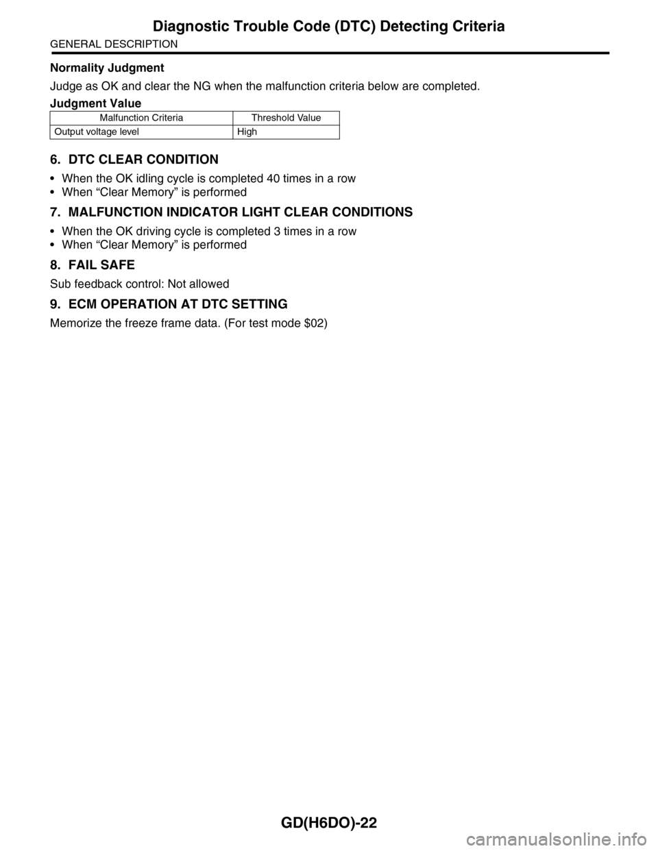
GD(H6DO)-22
Diagnostic Trouble Code (DTC) Detecting Criteria
GENERAL DESCRIPTION
Normality Judgment
Judge as OK and clear the NG when the malfunction criteria below are completed.
6. DTC CLEAR CONDITION
•When the OK idling cycle is completed 40 times in a row
•When “Clear Memory” is performed
7. MALFUNCTION INDICATOR LIGHT CLEAR CONDITIONS
•When the OK driving cycle is completed 3 times in a row
•When “Clear Memory” is performed
8. FAIL SAFE
Sub feedback control: Not allowed
9. ECM OPERATION AT DTC SETTING
Memorize the freeze frame data. (For test mode $02)
Judgment Value
Malfunction Criteria Threshold Value
Output voltage level High