2009 SUBARU TRIBECA Back up
[x] Cancel search: Back upPage 811 of 2453

DI-27
Rear Differential (VA–type)
DIFFERENTIALS
•Flank contact
Check item: Backlash is too small.
Contact pattern
Corrective action: Reduce the thickness of pinion
height adjusting washer according to the procedure for
bringing drive pinion away from hypoid driven gear.
•Toe contact (inner side contact)
Check item: Teeth contact area is too small.
Contact pattern
Corrective action: Reduce the thickness of pinion
height adjusting washer according to the procedure
for bringing drive pinion away from hypoid driven gear.
•Heel contact (outside end contact)
Check item: Teeth contact area is too small.
Contact pattern
Corrective action: Increase thickness of drive pin-
ion height adjusting washer in order to bring drive
pinion close to hypoid driven gear.
20) If proper tooth contact is not obtained, once
again adjust the drive pinion height and the differ-
ential side bearing preload (already mentioned)
and the hypoid gear backlash.
21) Attach a new gasket, rear cover, and ground
stay to the differential carrier.
Tightening torque:
34 N·m (3.5 kgf-m, 25.1 ft-lb)
22) Using new gaskets, install the rear differential
oil temperature switch.
Tightening torque:
60 N·m (6.1 kgf-m, 44.3 ft-lb)
AT-00209
AT-00213
AT-00210
AT-00213
AT-00211
AT-00212
DI-00477
Page 812 of 2453

DI-28
Rear Differential (VA–type)
DIFFERENTIALS
23) Affix with the attachment clip so that the white
marking of the hose is within the range of Z (87°).
E: INSPECTION
Wash all the disassembled parts clean, and exam-
ine them for wear, damage or other defects. Repair
or replace the defective parts as necessary.
1) Hypoid driven gear and drive pinion
•If there is evidently an abnormal tooth contact,
find out the cause and adjust until the teeth contact
correctly. Replace the gear if there is an excessive
worn or an incapable adjustment.
•If crack, cutout or seizure is found, replace the
parts as a set. Slight damage of some teeth can be
corrected by oil stone or the like.
2) Side gear and pinion mate gear
•Replace the differential case assembly if cracks,
scoring or other defects are evident on tooth sur-
face.
3) Bearing
Replace if seizure, peeling, wear, rust, dragging
during rotation, noise or other defect is evident.
4) Oil seal
Replace if deformed or damaged, and at every dis-
assembling.
5) Differential carrier
Replace if the bearing bores are worn or damaged.
6) Differential case
Replace if its sliding surfaces are worn or cracked.
7) Companion flange
Replace if the oil seal lip contact surface shows
cracking.
1. HYPOID DRIVEN GEAR BACKLASH
Using a dial gauge, check the backlash of hypoid
driven gear.
Hypoid driven gear backlash:
0.10 — 0.15 mm (0.0039 — 0.0059 in)
If the hypoid driven gear backlash is not within the
specification, adjust the side bearing preload or re-
pair if necessary.
2. TOOTH CONTACT BETWEEN HYPOID
DRIVEN GEAR AND DRIVE PINION
Inspect the tooth contact between the hypoid driv-
en gear and drive pinion.
3. COMPANION FLANGE
1) If rust or dirt is attached to the companion flange,
remove them.
2) Set a dial gauge at a companion flange surface
(mating surface of propeller shaft and companion
flange), and then measure the companion flange
runout.
Limit of runout:
0.08 mm (0.003 in)
(1) 0 — 1 mm (0 — 0.04 in)
(2) Marking
DI-00478
B
B
A
A
Z
(1)
(2)
DI-00099
DI-00360
Page 813 of 2453

DI-29
Rear Differential (VA–type)
DIFFERENTIALS
3) Set the gauge inside of the companion flange,
and measure the runout.
Limit of runout:
0.08 mm (0.003 in)
4) If either runout exceeds the limit, move the
phase of companion flange and drive pinion 90°
each, and find the point where the runout will be
within the limit.
5) If the runout exceeds the limit when changing
the phase, replace the companion flange and re-
check the runout.
6) If the runout exceeds the limit after replacing the
companion flange, the drive pinion may be assem-
bled incorrectly or bearing is faulty.
4. REAR DIFFERENTIAL OIL TEMPERA-
TURE SWITCH
Inspect the continuity of the rear differential oil tem-
perature switch.
F: ADJUSTMENT
1. HYPOID DRIVEN GEAR BACKLASH
Adjust hypoid driven gear backlash.
2. TOOTH CONTACT BETWEEN HYPOID
DRIVEN GEAR AND DRIVE PINION
Adjust the tooth contact between hypoid driven
gear and drive pinion gear.
Specified resistance Criteria
Less than 1 ΩNormal
1 MΩ or more Replacement
DI-00361
DI-00479
Page 818 of 2453

DI-34
General Diagnostic Table
DIFFERENTIALS
8. General Diagnostic Table
A: INSPECTION
Symptom or trouble Possible cause Remedy
1. Oil leakage(1) Worn, scratched, or incorrectly seated
front or side oil seal. Scored, battered or
excessively wor n sliding surface of com-
panion flange.
Correct or replace.
(2) Clogged or damaged air breather. Clean, repair or replace.
(3) Loose bolts on differential spindle or
side retainer, or incorrectly fitted O-ring.
Tighten the bolts to specified torque.
Replace the O-ring.
(4) Loose rear cover attaching bolts or
damaged gasket.
Tighten the bolts to specified torque.
Replace gasket and apply liquid gasket.
(5) Loose oil filler or drain plug. Retighten and apply liquid gasket.
(6) Wear, damage or incorrect fitting of
spindle, side retainer or oil seal.
Correct or replace.
2. Seizure
NOTE:Seized or damaged parts should be re-
placed, and also other parts should be thor-
oughly checked for any defect and should
be repaired or replaced as required.
(1) Insufficient backlash for hypoid gear. Readjust or replace.
(2) Excessive preload for side, rear or
front bearing.
Readjust or replace.
(3) Insufficient or improper oil used. Replace seized part and fill with speci-
fied oil to specified level.
3. Damage
NOTE:Damaged parts should be replaced, and
also other parts should be thoroughly
checked for any defect and should be re-
paired or replaced as required.
(1) Improper backlash for hypoid gear. Replace.
(2) Insufficient or excessive preload for
side, rear or front bearing.
Readjust or replace.
(3) Excessive backlash for differential
gear.
Replace gear or thrust washer.
(4) Loose bolts and nuts such as hypoid
driven gear bolt
Retighten.
(5) Damage due to overloading. Replace.
4. Noises when starting or shifting
gears
NOTE:
Noises may be caused by differential as-
sembly, universal joint, wheel bearing, etc.
Find out what is actually making noise be-
fore disassembling.
(1) Excessive backlash for hypoid gear. Readjust.
(2) Excessive backlash for differential
gear.
Replace the differential case assembly.
(3) Insufficient preload for front or rear
bearing.
Readjust.
(4) Loose drive pinion nut. Tighten to the specified torque.
(5) Loose bolts and nuts such as side
bearing retainer attaching bolt.
Tighten to the specified torque.
5. Noises when cornering(1) Damaged differential gear. Replace the differential case assembly.
(2) Excessive wear or damage of thrust
washer.
Replace the differential case assembly.
(3) Broken pinion mate shaft. Replace the differential case assembly.
(4) Seized or damaged side bearing. Replace.
6. Gear Noise
NOTE:
Since noises from engine, muffler, trans-
mission, propeller shaft, wheel bearings,
tires, and body are sometimes mistaken for
noises from differential assembly, be care-
ful in checking them. Inspection methods to
locate noises include coasting, accelerat-
ing, cruising, and jacking-up all four wheels.
Perform these inspections according to the
condition of trouble. When listening to nois-
es, shift gears into four wheel drive and
fourth speed position, trying to pick up only
differential noise.
(1) Improper tooth contact of hypoid gear. Readjust or replace hypoid gear set.
(2) Improper backlash of the hypoid gear. Readjust.
(3) Scored or chipped teeth of hypoid
gear.
Replace hypoid gear set.
(4) Seized hypoid gear. Replace hypoid gear set.
(5) Improper preload for front or rear
bearings.
Readjust.
(6) Seized, cut-away or chipped front or
rear bearing.
Replace.
(7) Seized, cut-away or chipped side
bearing.
Replace.
(8) Differential carrier is vibrating. Replace the differential case assembly.
Page 823 of 2453

DS-6
General Description
DRIVE SHAFT SYSTEM
3. REAR AXLE
(1) Baffle plate (DOJ) (8) Boot band (15) Axle nut (olive color)
(2) Outer race (DOJ) (9) Boot (DOJ)
(3) Snap ring (10) EBJ shaft ASSYTightening torque: N·m (kgf-m, ft-lb)
(4) Inner race (11) Rear housingT1: 75 (7.6, 55.3)
(5) Ball (12) Back plateT2: 65 (6.6, 47.9)
(6) Cage (13) Rear hub unit bearingT3: 240 (24.5, 177)
(7) Snap ring (14) Hub bolt
Page 833 of 2453

DS-16
Front Axle
DRIVE SHAFT SYSTEM
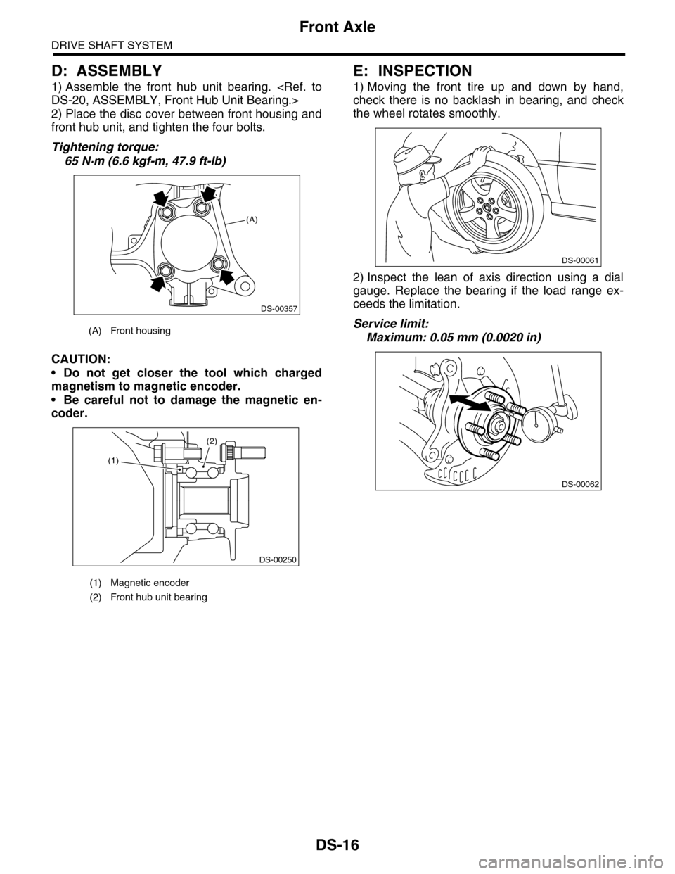
D: ASSEMBLY
1) Assemble the front hub unit bearing.
2) Place the disc cover between front housing and
front hub unit, and tighten the four bolts.
Tightening torque:
65 N·m (6.6 kgf-m, 47.9 ft-lb)
CAUTION:
•Do not get closer the tool which charged
magnetism to magnetic encoder.
•Be careful not to damage the magnetic en-
coder.
E: INSPECTION
1) Moving the front tire up and down by hand,
check there is no backlash in bearing, and check
the wheel rotates smoothly.
2) Inspect the lean of axis direction using a dial
gauge. Replace the bearing if the load range ex-
ceeds the limitation.
Service limit:
Maximum: 0.05 mm (0.0020 in)(A) Front housing
(1) Magnetic encoder
(2) Front hub unit bearing
(A)
DS-00357
(2)
DS-00250
(1)
DS-00061
DS-00062
Page 835 of 2453

DS-18
Rear Axle
DRIVE SHAFT SYSTEM
B: INSTALLATION
NOTE:
•Be sure to use a new self-locking nut.
•Always tighten the stabilizer bushing in the state
where the vehicle is at curb weight and the wheels
are in full contact with the ground.
Install in the reverse order of removal.
Tightening torque:
Refer to COMPONENT of General Description
for tightening torque.
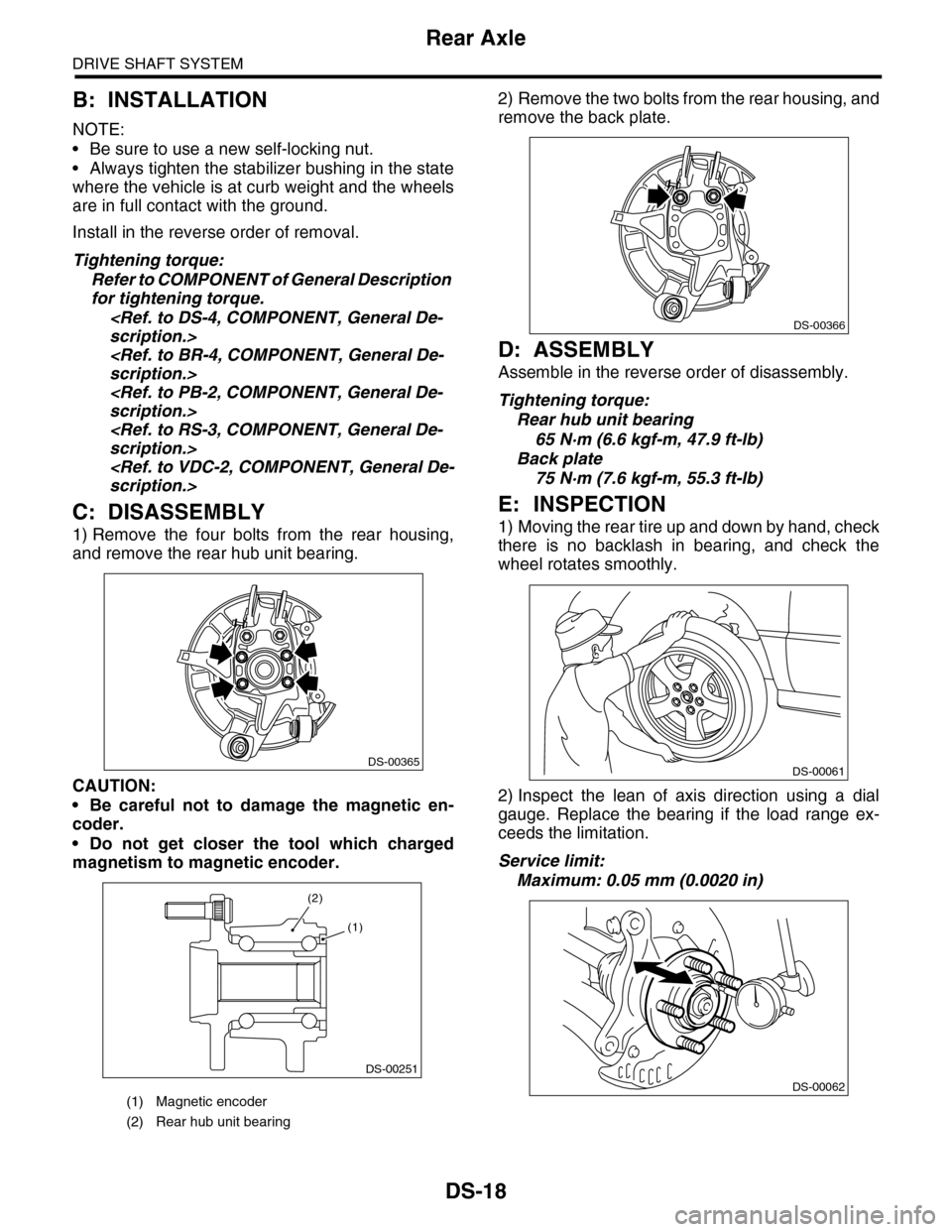
C: DISASSEMBLY
1) Remove the four bolts from the rear housing,
and remove the rear hub unit bearing.
CAUTION:
•Be careful not to damage the magnetic en-
coder.
•Do not get closer the tool which charged
magnetism to magnetic encoder.
2) Remove the two bolts from the rear housing, and
remove the back plate.
D: ASSEMBLY
Assemble in the reverse order of disassembly.
Tightening torque:
Rear hub unit bearing
65 N·m (6.6 kgf-m, 47.9 ft-lb)
Back plate
75 N·m (7.6 kgf-m, 55.3 ft-lb)
E: INSPECTION
1) Moving the rear tire up and down by hand, check
there is no backlash in bearing, and check the
wheel rotates smoothly.
2) Inspect the lean of axis direction using a dial
gauge. Replace the bearing if the load range ex-
ceeds the limitation.
Service limit:
Maximum: 0.05 mm (0.0020 in)
(1) Magnetic encoder
(2) Rear hub unit bearing
DS-00365
DS-00251
(2)
(1)
DS-00366
DS-00061
DS-00062
Page 839 of 2453

DS-22
Rear Hub Unit Bearing
DRIVE SHAFT SYSTEM
NOTE:
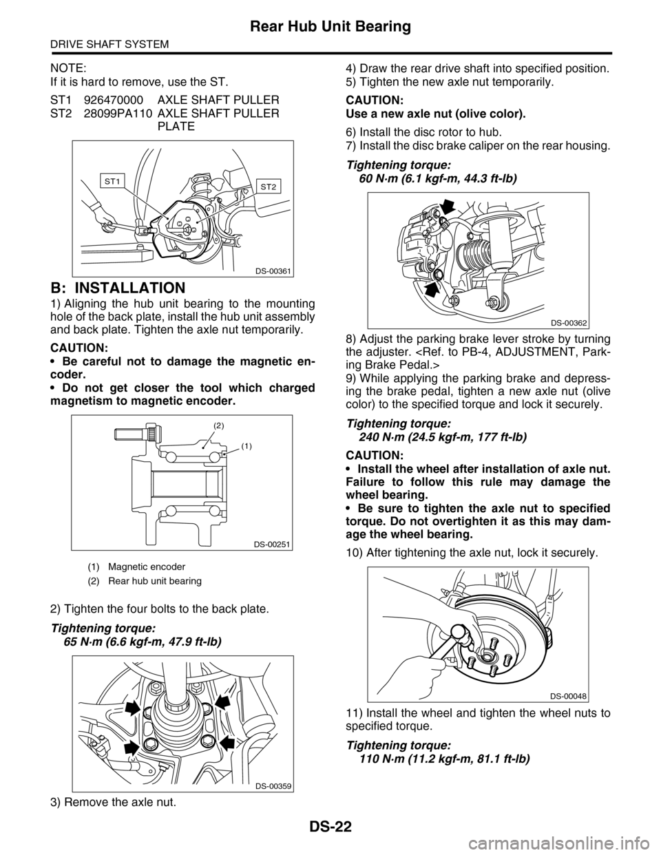
If it is hard to remove, use the ST.
ST1 926470000 AXLE SHAFT PULLER
ST2 28099PA110 AXLE SHAFT PULLER
PLATE
B: INSTALLATION
1) Aligning the hub unit bearing to the mounting
hole of the back plate, install the hub unit assembly
and back plate. Tighten the axle nut temporarily.
CAUTION:
•Be careful not to damage the magnetic en-
coder.
•Do not get closer the tool which charged
magnetism to magnetic encoder.
2) Tighten the four bolts to the back plate.
Tightening torque:
65 N·m (6.6 kgf-m, 47.9 ft-lb)
3) Remove the axle nut.
4) Draw the rear drive shaft into specified position.
5) Tighten the new axle nut temporarily.
CAUTION:
Use a new axle nut (olive color).
6) Install the disc rotor to hub.
7) Install the disc brake caliper on the rear housing.
Tightening torque:
60 N·m (6.1 kgf-m, 44.3 ft-lb)
8) Adjust the parking brake lever stroke by turning
the adjuster.
9) While applying the parking brake and depress-
ing the brake pedal, tighten a new axle nut (olive
color) to the specified torque and lock it securely.
Tightening torque:
240 N·m (24.5 kgf-m, 177 ft-lb)
CAUTION:
•Install the wheel after installation of axle nut.
Failure to follow this rule may damage the
wheel bearing.
•Be sure to tighten the axle nut to specified
torque. Do not overtighten it as this may dam-
age the wheel bearing.
10) After tightening the axle nut, lock it securely.
11) Install the wheel and tighten the wheel nuts to
specified torque.
Tightening torque:
110 N·m (11.2 kgf-m, 81.1 ft-lb)
(1) Magnetic encoder
(2) Rear hub unit bearing
ST2ST1
DS-00361
DS-00251
(2)
(1)
DS-00359
DS-00362
DS-00048