2009 SUBARU TRIBECA Back up
[x] Cancel search: Back upPage 904 of 2453
PS-24
Steering Gearbox
POWER ASSISTED SYSTEM (POWER STEERING)
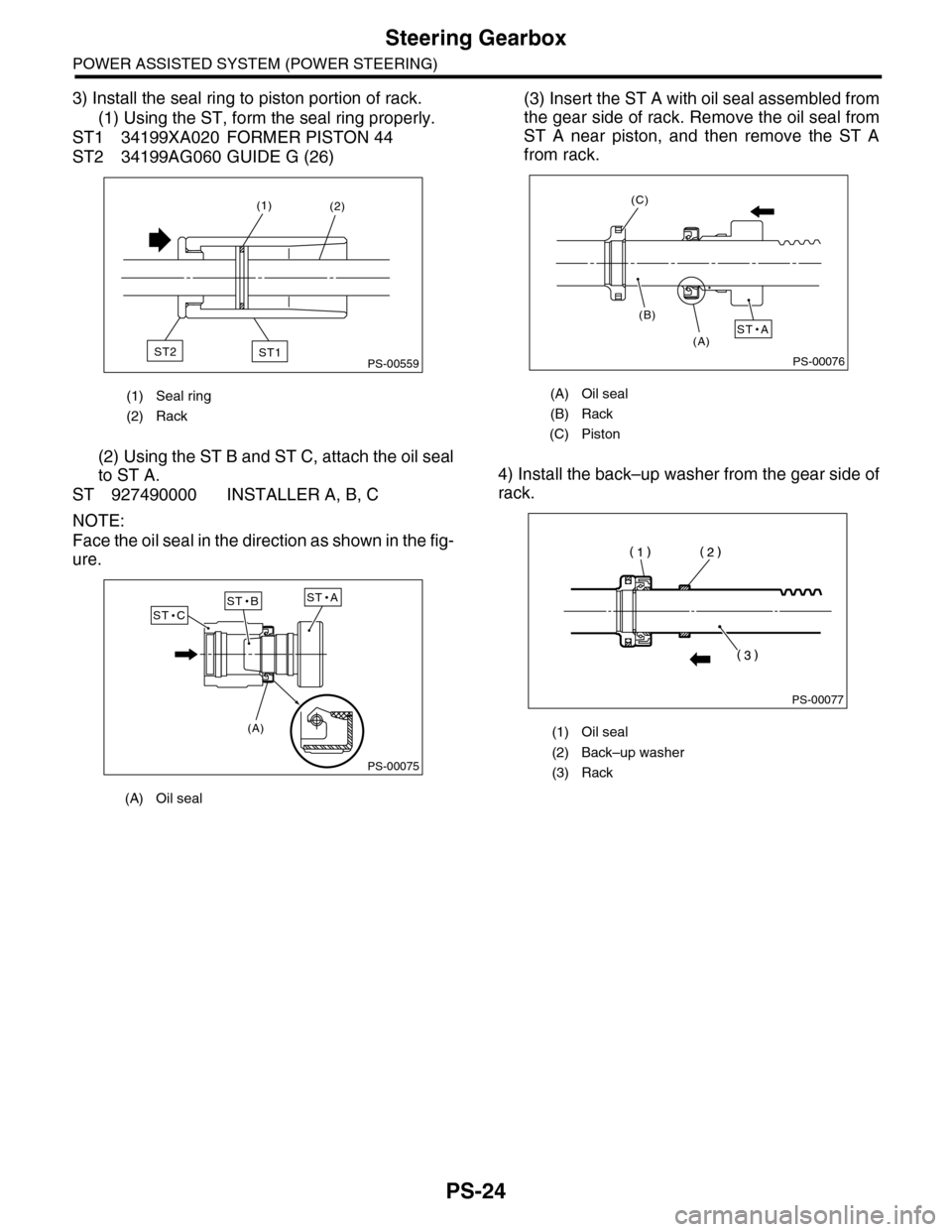
3) Install the seal ring to piston portion of rack.
(1) Using the ST, form the seal ring properly.
ST1 34199XA020 FORMER PISTON 44
ST2 34199AG060 GUIDE G (26)
(2) Using the ST B and ST C, attach the oil seal
to ST A.
ST 927490000 INSTALLER A, B, C
NOTE:
Face the oil seal in the direction as shown in the fig-
ure.
(3) Insert the ST A with oil seal assembled from
the gear side of rack. Remove the oil seal from
ST A near piston, and then remove the ST A
from rack.
4) Install the back–up washer from the gear side of
rack.
(1) Seal ring
(2) Rack
(A) Oil seal
PS-00559
(2)(1)
ST1ST2
PS-00075
ST AST BST C
(A)
(A) Oil seal
(B) Rack
(C) Piston
(1) Oil seal
(2) Back–up washer
(3) Rack
PS-00076
ST A(A)
(B)
(C)
PS-00077
Page 910 of 2453
PS-30
Steering Gearbox
POWER ASSISTED SYSTEM (POWER STEERING)
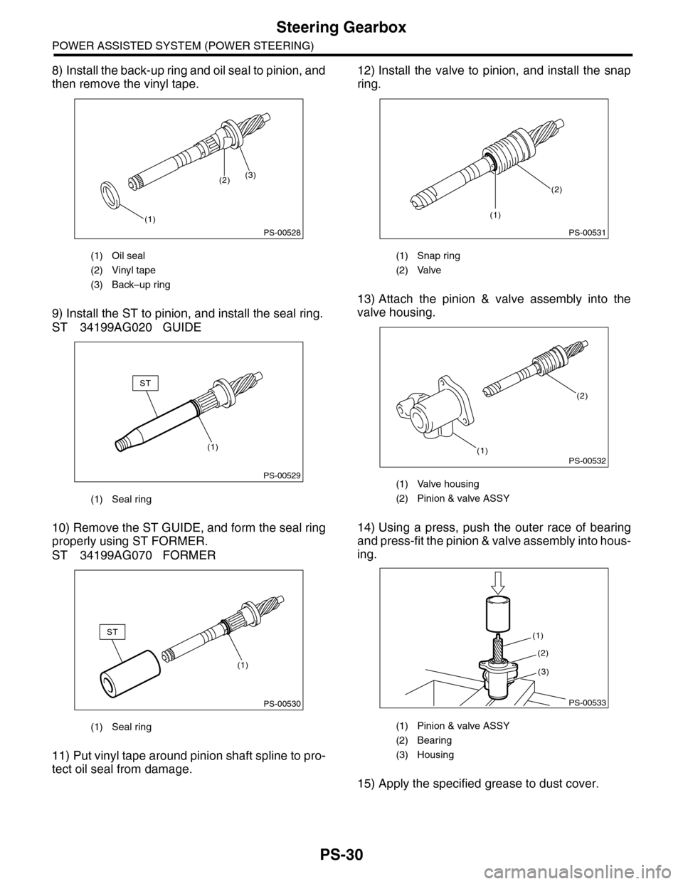
8) Install the back-up ring and oil seal to pinion, and
then remove the vinyl tape.
9) Install the ST to pinion, and install the seal ring.
ST 34199AG020 GUIDE
10) Remove the ST GUIDE, and form the seal ring
properly using ST FORMER.
ST 34199AG070 FORMER
11) Put vinyl tape around pinion shaft spline to pro-
tect oil seal from damage.
12) Install the valve to pinion, and install the snap
ring.
13) Attach the pinion & valve assembly into the
valve housing.
14) Using a press, push the outer race of bearing
and press-fit the pinion & valve assembly into hous-
ing.
15) Apply the specified grease to dust cover.
(1) Oil seal
(2) Vinyl tape
(3) Back–up ring
(1) Seal ring
(1) Seal ring
PS-00528
(1)
(2)(3)
PS-00529
(1)
ST
PS-00530
ST
(1)
(1) Snap ring
(2) Valve
(1) Valve housing
(2) Pinion & valve ASSY
(1) Pinion & valve ASSY
(2) Bearing
(3) Housing
PS-00531
(2)
(1)
PS-00532(1)
(2)
PS-00533
(1)
(2)
(3)
Page 913 of 2453

PS-33
Steering Gearbox
POWER ASSISTED SYSTEM (POWER STEERING)
E: INSPECTION
1. BASIC INSPECTION
1) Clean all the disassembled parts, and check for wear, damage or any other faults, then repair or replace
as necessary.
2) When disassembling, check the inside of gearbox for water. If any water is found, carefully check the boot
for damage, input shaft dust seal, adjusting screw and boot clips for poor sealing. If faulty, replace with new
parts.
No. Parts Inspection Corrective action
1Input shaft(1) Bent input shaft
(2) Damage on serration
If the bend or damage is excessive, replace the entire
gearbox.
2Dust seal(1) Crack or damage
(2) Wear
If the outer wall slips, the lip is worn out or damage is
found, replace it with a new one.
3Rack & pinion Poor mating of rack with pinion
(1) Adjust the backlash properly.
By measuring the turning torque of the gearbox and slid-
ing resistance of rack, check if the rack & pinion engage
uniformly and smoothly with each other. (Refer to “Ser-
vice limit”.)
(2) Pull out the entire rack to allow viewing of the teeth,
and check for damage.
Even if abnormality is found in either (1) or (2), replace
the entire gearbox.
4Gearbox unit
(1) Bending of the rack shaft
(2) Bending of the cylinder portion
(3) Crack or damage on the cast
iron portion
Replace the gearbox with a new one.
(4) Wear or damage on rack bush-
ing
If the free play of rack shaft in radial direction is out of the
specified range, replace the gearbox with new one. (Refer
to “Service limit”.)
(5) Wear on input shaft bearing
If the free play of input shaft in radial and axial direction is
out of the specified range, replace the gearbox with a new
one. (Refer to “Service limit”.)
5Boot Crack, damage or deteriorationReplace.
6Tie–rod(1) Looseness of ball joint
(2) Bend of tie–rodReplace.
7Tie–rod endDamage or deterioration of dust
sealReplace.
8Adjusting screw
springDeterioration Replace.
9Boot clip Deterioration Replace.
10 Sleeve Damage Replace.
11 Pipe
(1) Damage to flared surface
(2) Damage to flare nut
(3) Damage to pipe
Replace.
Page 930 of 2453

PS-50
General Diagnostic Table
POWER ASSISTED SYSTEM (POWER STEERING)
1. NOISE & VIBRATION
CAUTION:
Do not keep the relief valve operated over five seconds at any time or inner parts of the oil pump may
be damaged due to rapid increase of fluid temperature.
NOTE:
•A screeching noise may be heard immediately after the engine start in extremely cold conditions. In this
case, if the noise goes off during warm-up there is no abnormal function in the system. This is due to the fluid
characteristics in extremely cold condition.
•The oil pump normally makes a small whining noise due to its mechanism. Even if a noise is heard when
steering wheel is turned at stand still, there is no abnormal function in the system provided that the noise
eliminates when the vehicle is driving.
•When turning the steering wheel with the brake applied when the vehicle is parked, a screeching noise
may be generated by the brake disc and pads. This is not a fault in the steering system.
•There may be a small vibration around the steering devices when turning the steering wheel at standstill,
even though the component parts are operating properly.
Hydraulic systems are likely to generate this kind of vibration as well as working noise and fluid noise be-
cause of combined conditions, i.e., road surface and tire surface, engine speed and turning speed of steering
wheel, fluid temperature and braking condition.
These conditions do not indicate a problem in the system.
Confirm vibration for an AT model, by applying the parking brake on a concrete surface, shifting into the “D”
range, and turning the steering wheel repeatedly from slow to rapid, step by step.
Tr o u b l e P o s s i b l e c a u s e C o r r e c t i v e a c t i o n
Hiss noise (continuous)
While engine is running.
Relief valve emits operating sound when steering wheel is
completely turned in either direction. (Do not keep this
condition over five seconds.)
Normal
Relief valve emits operating sound when steering wheel is
not turned. This means that the relief valve is defective. Replace the oil pump.
Rattling noise (intermittent)
While engine is running.
Interference with adjacent parts
Check the clearance.
Correct if necessary.
Loosened installation of oil pump, oil tank, pump bracket,
gearbox or crossmemberRetighten.
Loose oil pump pulley or other pulley(s) Retighten.
Looseness of linkage, play of steering, improper tightening
(looseness) of suspension joint or steering columnRetighten or replace.
Sound generates from the inside of gearbox or oil pump.Replace faulty parts in the gear-
box or oil pump.
Knocking
When turning steering wheel in
both directions with small angle
repeatedly at engine ON or OFF.
Excessive backlash
Loosened lock nut for adjusting backlashAdjust and retighten.
Insufficient tightening or play in the tie–rod or tie–rod end Retighten or replace.
Grinding noise (continuous)
While engine is running.
Air in vane pump
Inspect and retighten the fluid
line connection.
Refill the fluid and vent air.
Va n e p u m p s e i z i n g R e p l a c e t h e o i l p u m p.
Oil pump pulley bearing seized Replace the oil pump.
Folded hose, flattened pipe Replace.
Squeal, squeak (intermittent or
continuous)
While engine is running.
Improper adjustment of pulley belt
Damaged or over tensioned pulley belt
Unequal length of pulley belts
Adjust or replace.
(Replace two belts as a set.)
Runout or dirty V–groove surface of oil pump pulley Clean or replace.
Page 932 of 2453

PS-52
General Diagnostic Table
POWER ASSISTED SYSTEM (POWER STEERING)
2. MEASUREMENT OF STEERING EFFORT
Step Check Yes No
1CHECK STEERING EFFORT.
1) Stop the vehicle on paved road.
2) Start the engine.
3) Run the engine at idle.
4) Install a spring scale on the steering wheel.
5) Pull the spring scale at a right angle to the
steering wheel, and measure both right and left
steering wheel efforts.
NOTE:When turning the steering more quickly than
necessary from a direction to the other direction
at an engine speed over 2,000 rpm, steering ef-
fort may be heavy. This is caused by flow char-
acteristic of the fluid in the oil pump and is not a
defect.
Is the steering effort less than
29.4 N (3.0 kgf, 6.6 lb)?
Go to step 2.Adjust the back-
lash.
2CHECK STEERING EFFORT.
1) Stop the engine.
2) Pull the spring scale at a right angle to the
steering wheel, and measure both right and left
steering wheel efforts.
Is the steering effort less than
294.2 N (30 kgf, 66.2 lb)?
Go to step 3.Perform the
adjustment.
3CHECK STEERING WHEEL EFFORT.
1) Remove the universal joint.
2) Measure the steering wheel effort.
Is steering effort less than 2.26
N (0.23 kgf, 0.51 lb)?
Go to step 4.Check, adjust and
replace if neces-
sary.
4CHECK STEERING WHEEL EFFORT.
Measure the steering wheel effort.
Is the difference of steering
effort between right and left
less than 20%?
Go to step 5.Check, adjust and
replace if neces-
sary.
5CHECK UNIVERSAL JOINT.
Measure the swing torque of the joint (yoke of
steering column side).
Is the swing torque of the uni-
versal joint less than 7.3 N
(0.74 kgf, 1.64 lb)?
Go to step 6.Replace with a
new part.
6CHECK UNIVERSAL JOINT.
Measure the swing torque of the joint (yoke of
gearbox side).
Is the swing torque of the uni-
versal joint less than 3.8 N
(0.39 kgf, 0.86 lb)?
Go to step 7.Replace with a
new part.
7CHECK FRONT WHEEL.
Check the front wheels.
Does the front wheels have
unsteady revolution or rattling,
or does the brake drag?
Inspect, readjust
and replace if nec-
essary.
Go to step 8.
8CHECK TIE–ROD ENDS.
Remove the tie–rod ends.
If the tie-rod ends of suspen-
sion have unsteady revolution
or rattling?
Inspect and
replace if neces-
sary.
Go to step 9.
9BALL JOINT CHECK.
Remove the ball joint.
If the ball joints of suspension
have unsteady revolution or
rattling?
Inspect and
replace if neces-
sary.
Go to step 10.
10 CHECK GEARBOX.
Measure the rotating of gearbox.
box.>
Is the rotating resistance of
steering gearbox less than
10.5 N (1.1 kgf, 2.4 lb)? Is the
difference between right and
left sides less than 20%?
Go to step 11.Readjust the back-
lash, and if ineffec-
tive, replace the
faulty par ts.
11 CHECK GEARBOX.
Measure the sliding of gearbox.
Is the sliding resistance of
steering gearbox less than 400
N (41 kgf, 90 lb)? Is the differ-
ence between the right and left
sliding resistance less than
20%?
Steering effort is
normal.
Readjust the back-
lash, and if ineffec-
tive, replace the
faulty par ts.
Page 936 of 2453
RS-3
General Description
REAR SUSPENSION
B: COMPONENT
1. REAR SUSPENSION
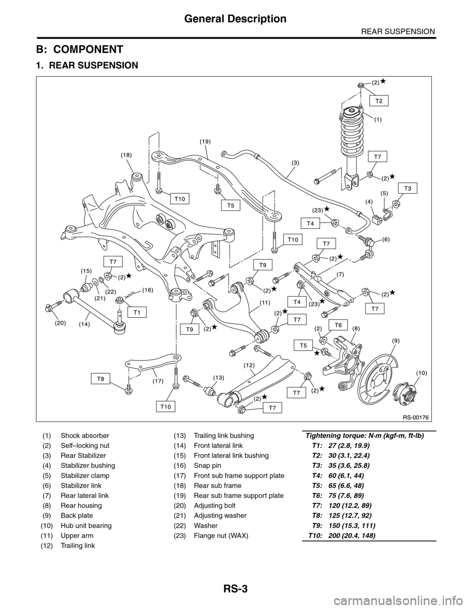
(1) Shock absorber (13) Trailing link bushingTightening torque: N·m (kgf-m, ft-lb)
(2) Self–locking nut (14) Front lateral linkT1: 27 (2.8, 19.9)
(3) Rear Stabilizer (15) Front lateral link bushingT2: 30 (3.1, 22.4)
(4) Stabilizer bushing (16) Snap pinT3: 35 (3.6, 25.8)
(5) Stabilizer clamp (17) Front sub frame support plateT4: 60 (6.1, 44)
(6) Stabilizer link (18) Rear sub frameT5: 65 (6.6, 48)
(7) Rear lateral link (19) Rear sub frame support plateT6: 75 (7.6, 89)
(8) Rear housing (20) Adjusting boltT7: 120 (12.2, 89)
(9) Back plate (21) Adjusting washerT8: 125 (12.7, 92)
(10) Hub unit bearing (22) WasherT9: 150 (15.3, 111)
(11) Upper arm (23) Flange nut (WAX)T10: 200 (20.4, 148)
(12) Trailing link
Page 1089 of 2453
VDC-8
VDC Control Module & Hydraulic Control Unit (VDCCM&H/U)
VEHICLE DYNAMICS CONTROL (VDC)
4) Connect the VDCCM&H/U connectors.
NOTE:
•Be sure to remove all foreign matter from inside
the connector before connecting.
•Make sure the VDCCM&H/U connector is se-
curely locked.
5) Bleed air from the brake system.
C: INSPECTION
1) Check the condition of connection and settle-
ment of connector.
2) Check the mark used for VDCCM&H/U identifi-
cation.
Refer to “SPECIFICATION” for the identification
mark.
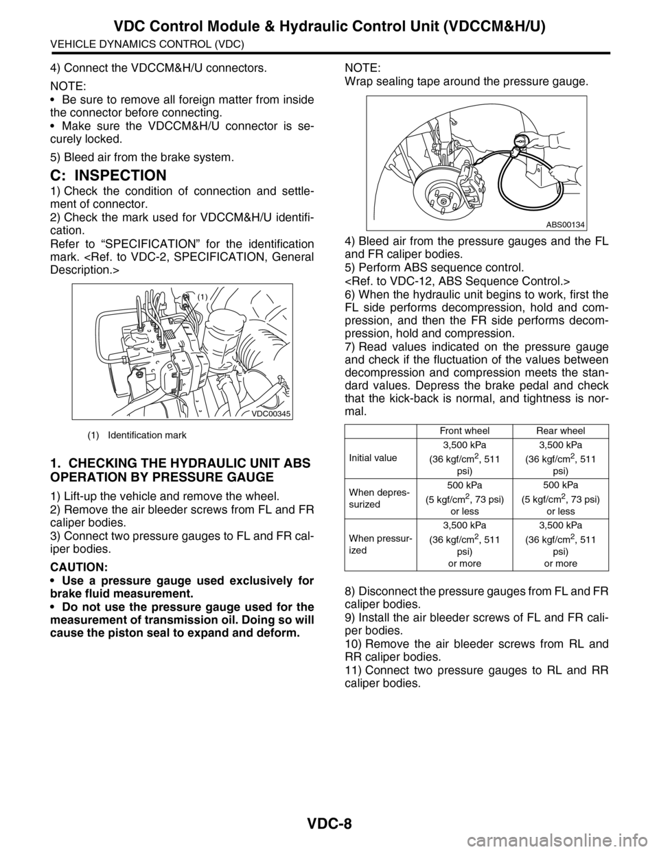
1. CHECKING THE HYDRAULIC UNIT ABS
OPERATION BY PRESSURE GAUGE
1) Lift-up the vehicle and remove the wheel.
2) Remove the air bleeder screws from FL and FR
caliper bodies.
3) Connect two pressure gauges to FL and FR cal-
iper bodies.
CAUTION:
•Use a pressure gauge used exclusively for
brake fluid measurement.
•Do not use the pressure gauge used for the
measurement of transmission oil. Doing so will
cause the piston seal to expand and deform.
NOTE:
Wrap sealing tape around the pressure gauge.
4) Bleed air from the pressure gauges and the FL
and FR caliper bodies.
5) Perform ABS sequence control.
6) When the hydraulic unit begins to work, first the
FL side performs decompression, hold and com-
pression, and then the FR side performs decom-
pression, hold and compression.
7) Read values indicated on the pressure gauge
and check if the fluctuation of the values between
decompression and compression meets the stan-
dard values. Depress the brake pedal and check
that the kick-back is normal, and tightness is nor-
mal.
8) Disconnect the pressure gauges from FL and FR
caliper bodies.
9) Install the air bleeder screws of FL and FR cali-
per bodies.
10) Remove the air bleeder screws from RL and
RR caliper bodies.
11) Connect two pressure gauges to RL and RR
caliper bodies.
(1) Identification mark
VDC00345
(1)
Front wheelRear wheel
Initial value
3,500 kPa
(36 kgf/cm2, 511
psi)
3,500 kPa
(36 kgf/cm2, 511
psi)
When depres-
surized
500 kPa
(5 kgf/cm2, 73 psi)
or less
500 kPa
(5 kgf/cm2, 73 psi)
or less
When pressur-
ized
3,500 kPa
(36 kgf/cm2, 511
psi)
or more
3,500 kPa
(36 kgf/cm2, 511
psi)
or more
ABS00134
Page 1090 of 2453
VDC-9
VDC Control Module & Hydraulic Control Unit (VDCCM&H/U)
VEHICLE DYNAMICS CONTROL (VDC)
12) Bleed air from the brake system.
13) Bleed air from RL and RR caliper bodies, and
pressure gauge.
14) Perform ABS sequence control.
15) When the hydraulic unit begins to work, first the
RR side performs decompression, hold and com-
pression, and then the RL side performs decom-
pression, hold and compression.
16) Read values indicated on the pressure gauge
and check if the fluctuation of the values between
decompression and compression meets specifica-
tion. Depress the brake pedal and check that the
kick-back is normal, and tightness is normal.
17) Disconnect the pressure gauge from the RL
and RR caliper bodies.
18) Install the air bleeder screws of RL and RR cal-
iper bodies.
19) Bleed air from the brake system.
2. CHECKING THE HYDRAULIC UNIT ABS
OPERATION WITH THE BRAKE TESTER
1) Set wheels other than the one to measure free
rollers.
2) Prepare for the ABS sequence control operation.
3) Set the front wheels or rear wheels on the brake
tester and set the select lever position to the “N”
range.
4) Operate the brake tester.
5) Perform ABS sequence control.
6) When the hydraulic unit begins to work, check
the following work sequence.
(1) The FL wheel performs decompression,
hold and compression in sequence, and subse-
quently the FR wheel repeats the cycle.
(2) The RR wheel performs decompression,
hold and compression in sequence, and subse-
quently the RL wheel repeats the cycle.
7) Read values indicated on the brake tester and
check if the fluctuation of the values between de-
compression and compression meets specifica-
tion.
8) After the inspection, depress the brake pedal
and check that it is not abnormally hard, and tight-
ness is normal.
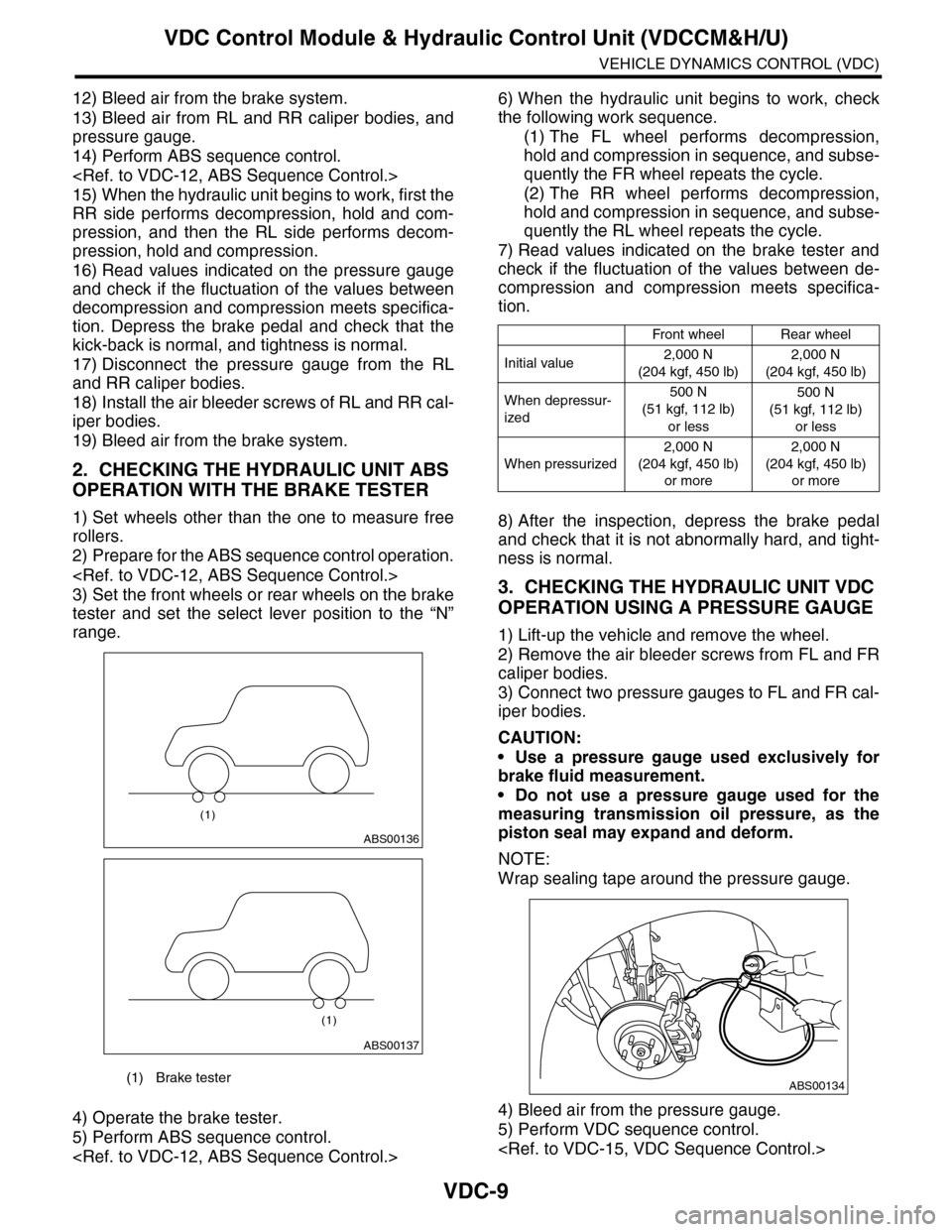
3. CHECKING THE HYDRAULIC UNIT VDC
OPERATION USING A PRESSURE GAUGE
1) Lift-up the vehicle and remove the wheel.
2) Remove the air bleeder screws from FL and FR
caliper bodies.
3) Connect two pressure gauges to FL and FR cal-
iper bodies.
CAUTION:
•Use a pressure gauge used exclusively for
brake fluid measurement.
•Do not use a pressure gauge used for the
measuring transmission oil pressure, as the
piston seal may expand and deform.
NOTE:
Wrap sealing tape around the pressure gauge.
4) Bleed air from the pressure gauge.
5) Perform VDC sequence control.
(1) Brake tester
ABS00136
(1)
ABS00137
(1)
Front wheelRear wheel
Initial value2,000 N
(204 kgf, 450 lb)
2,000 N
(204 kgf, 450 lb)
When depressur-
ized
500 N
(51 kgf, 112 lb)
or less
500 N
(51 kgf, 112 lb)
or less
When pressurized
2,000 N
(204 kgf, 450 lb)
or more
2,000 N
(204 kgf, 450 lb)
or more
ABS00134