Page 840 of 2453

DS-23
Rear Hub Unit Bearing
DRIVE SHAFT SYSTEM
C: DISASSEMBLY
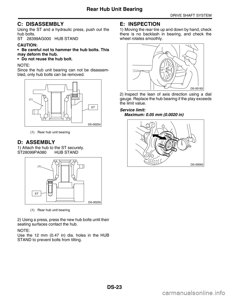
Using the ST and a hydraulic press, push out the
hub bolts.
ST 28399AG000 HUB STAND
CAUTION:
•Be careful not to hammer the hub bolts. This
may deform the hub.
•Do not reuse the hub bolt.
NOTE:
Since the hub unit bearing can not be disassem-
bled, only hub bolts can be removed.
D: ASSEMBLY
1) Attach the hub to the ST securely.
ST28099PA080 HUB STAND
2) Using a press, press the new hub bolts until their
seating surfaces contact the hub.
NOTE:
Use the 12 mm (0.47 in) dia. holes in the HUB
STAND to prevent bolts from tilting.
E: INSPECTION
1) Moving the rear tire up and down by hand, check
there is no backlash in bearing, and check the
wheel rotates smoothly.
2) Inspect the lean of axis direction using a dial
gauge. Replace the hub bearing if the play exceeds
the limit value.
Service limit:
Maximum: 0.05 mm (0.0020 in)
(1) Rear hub unit bearing
(1) Rear hub unit bearing
DS-00254
ST
(1)
DS-00255
ST
(1)
DS-00183
DS-00062
Page 873 of 2453
PB-2
General Description
PARKING BRAKE
1. General Description
A: SPECIFICATION
B: COMPONENT
1. PARKING BRAKE (REAR DISC BRAKE)
Ty p e M e c h a n i c a l , d r u m i n d i s c r e a r b r a k e s
Effective drum diameter mm (in) 210 (8.27)
Lining dimensions
(Length×Width×Thickness)mm (in)238.2 × 30.0 × 4.0
(9.378 × 1.181 × 0.157)
Clearance adjustment Manual adjustment
Pe da l s t ro ke n o tc he s /N ( k gf, lb ) 5 — 6 / 3 00 ( 30 . 6, 6 7)
(1) Back plate (8) Strut (15) Shoe hold pin
(2) Retainer (9) Primary return spring (16) Self locking nut (with WAX)
(3) Spring washer (10) Secondary return spring
(4) Lever (11) Adjusting springTightening torque: N·m (kgf-m, ft-lb)
(5) Parking brake shoe (Primary) (12) AdjusterT1: 8 (0.8, 5.9)
(6) Parking brake shoe (Secondary) (13) Brake shoe cupT2: 75 (7.6, 55.33)
(7) Strut spring (14) Brake shoe spring
PB-00083
(5)
(14)
(13)
(12)(9)
(11)
(10)
(8)
(7)
(6)
(4)(3)(2)
(1)
(15)
(16)
T1
T2
Page 879 of 2453

PB-8
Parking Brake Assembly (Rear Disc Brake)
PARKING BRAKE
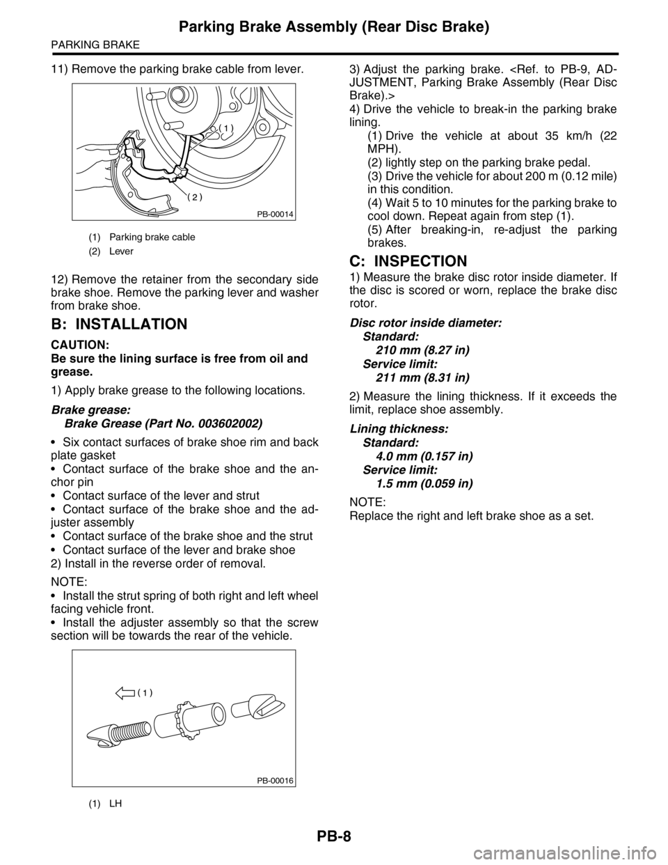
11) Remove the parking brake cable from lever.
12) Remove the retainer from the secondary side
brake shoe. Remove the parking lever and washer
from brake shoe.
B: INSTALLATION
CAUTION:
Be sure the lining surface is free from oil and
grease.
1) Apply brake grease to the following locations.
Brake grease:
Brake Grease (Part No. 003602002)
•Six contact surfaces of brake shoe rim and back
plate gasket
•Contact surface of the brake shoe and the an-
chor pin
•Contact surface of the lever and strut
•Contact surface of the brake shoe and the ad-
juster assembly
•Contact surface of the brake shoe and the strut
•Contact surface of the lever and brake shoe
2) Install in the reverse order of removal.
NOTE:
•Install the strut spring of both right and left wheel
facing vehicle front.
•Install the adjuster assembly so that the screw
section will be towards the rear of the vehicle.
3) Adjust the parking brake.
JUSTMENT, Parking Brake Assembly (Rear Disc
Brake).>
4) Drive the vehicle to break-in the parking brake
lining.
(1) Drive the vehicle at about 35 km/h (22
MPH).
(2) lightly step on the parking brake pedal.
(3) Drive the vehicle for about 200 m (0.12 mile)
in this condition.
(4) Wait 5 to 10 minutes for the parking brake to
cool down. Repeat again from step (1).
(5) After breaking-in, re-adjust the parking
brakes.
C: INSPECTION
1) Measure the brake disc rotor inside diameter. If
the disc is scored or worn, replace the brake disc
rotor.
Disc rotor inside diameter:
Standard:
210 mm (8.27 in)
Service limit:
211 mm (8.31 in)
2) Measure the lining thickness. If it exceeds the
limit, replace shoe assembly.
Lining thickness:
Standard:
4.0 mm (0.157 in)
Service limit:
1.5 mm (0.059 in)
NOTE:
Replace the right and left brake shoe as a set.
(1) Parking brake cable
(2) Lever
(1) LH
PB-00014
PB-00016
Page 880 of 2453

PB-9
Parking Brake Assembly (Rear Disc Brake)
PARKING BRAKE
D: ADJUSTMENT
1. SHOE CLEARANCE
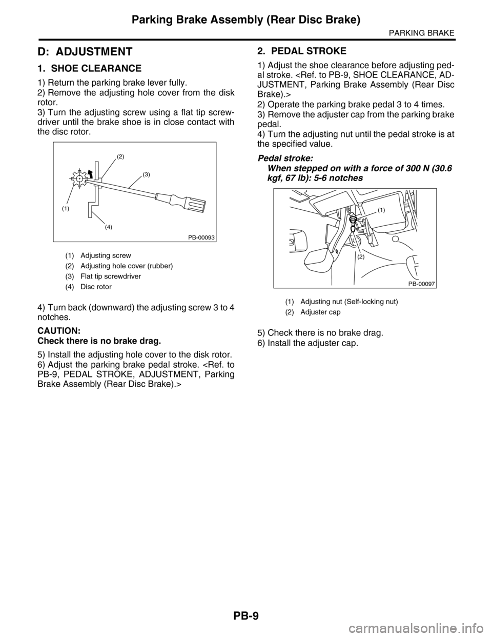
1) Return the parking brake lever fully.
2) Remove the adjusting hole cover from the disk
rotor.
3) Turn the adjusting screw using a flat tip screw-
driver until the brake shoe is in close contact with
the disc rotor.
4) Turn back (downward) the adjusting screw 3 to 4
notches.
CAUTION:
Check there is no brake drag.
5) Install the adjusting hole cover to the disk rotor.
6) Adjust the parking brake pedal stroke.
PB-9, PEDAL STROKE, ADJUSTMENT, Parking
Brake Assembly (Rear Disc Brake).>
2. PEDAL STROKE
1) Adjust the shoe clearance before adjusting ped-
al stroke.
JUSTMENT, Parking Brake Assembly (Rear Disc
Brake).>
2) Operate the parking brake pedal 3 to 4 times.
3) Remove the adjuster cap from the parking brake
pedal.
4) Turn the adjusting nut until the pedal stroke is at
the specified value.
Pedal stroke:
When stepped on with a force of 300 N (30.6
kgf, 67 lb): 5-6 notches
5) Check there is no brake drag.
6) Install the adjuster cap.
(1) Adjusting screw
(2) Adjusting hole cover (rubber)
(3) Flat tip screwdriver
(4) Disc rotor
(1)
(4)
(2)
(3)
PB-00093
(1) Adjusting nut (Self-locking nut)
(2) Adjuster cap
PB-00097
(1)
(2)
Page 882 of 2453

PS-2
General Description
POWER ASSISTED SYSTEM (POWER STEERING)
1. General Description
A: SPECIFICATION
Whole system
Minimum turning radius m (ft) 5.7 (18.7)
Steering angleInner wheel 37.0°±1.5°
Outer wheel 32.0°±1.5
Steering wheel diameter mm (in) 375 (14.76)
Lock to lock turn 3.44
Gearbox
Ty p e R a c k a n d P i n i o n , I n t e g r a l
Backlash 0 (Automatic adjusting)
Va l ve ( Po w e r s t e e r i n g s y s t e m ) R o t a r y va l ve
Pump
(Power steering
system)
Ty p e Va n e p u m p
Oil tank Installed on body
Specific outputcm3 (cu in)/rev.9.6 (0.586)
Relief pressurekPa (kg/cm2, psi)8,800 — 9,400 (90 — 96, 1,276 — 1,363)
Hydraulic fluid control Engine RPM sensitive
Hydraulic fluid2(US qt, Imp qt)1,000 rpm: 7.0 (7.4, 6.2)
3,000 rpm: 6.0 (6.3, 5.3)
RPM Range rpm 500 — 8,600
Direction of rotation Clockwise
Hydraulic oil
(Power steering
system)
Description ATF DEXRON III or equivalent
Capacity
2(US qt, Imp qt)
Oil tank 0.2 (0.2, 0.2)
Whole system 0.9 (1.0, 0.8)
Steering wheel Free play mm (in) 17 (0.67)
Steering shaftClearance between the steering wheel and
column covermm (in) 3.0 (0.12)
Steering gear-
box
(Power steering
system)
Sliding resistance N (kgf, lb)
400 (41, 90) or less
Difference between right and left sliding resistance:
Less than 20%
Rack shaft play in
the radial direction
Right–turn steering mm (in) 0.19 (0.0075) or less
Left–turn steering mm (in)Horizontal movement: 0.6 (0.024) or less
Ve r t i c a l m o v e m e n t : 0 . 4 ( 0 . 0 1 6 ) o r l e s s
Input shaft playIn radial direction mm (in) 0.18 (0.0071) or less
In axial direction mm (in) 0.27 (0.0106) or less
Rotation resistance N (kgf, lb)
Maximum allowable value: 10.5 (1.07, 2.36) or less
Difference between right and left sliding resistance:
Less than 20%
Oil Pump
(Power steering
system)
Pulley shaftRadial play mm (in) 0.2 (0.008) or less
Axial play mm (in) 0.6 (0.024) or less
PulleyDitch deflection mm (in) 1.0 (0.039) or less
Rotation resistance N (kgf, lb) 9.22 (0.94, 2.07) or less
Regular pressure (Unloaded)kPa (kg/cm2, psi)981 (10, 142) or less
Steering wheel
effort (Power
steering sys-
tem)
At standstill with engine idling on paved road N (kgf, lb) 29.4 (3.0, 6.6) or less
At standstill with engine stalled on paved
roadN (kgf, lb) 294.2 (30, 66.2) or less
Page 885 of 2453

PS-5
General Description
POWER ASSISTED SYSTEM (POWER STEERING)
•Gearbox
(1) Pipe C (20) Adapter (39) O–ring
(2) Pipe D (21) Clamp (40) Bracket
(3) Clamp plate (22) Cotter pin (41) Bushing
(4) Universal joint (23) Castle nut (42) Lock washer
(5) Dust seal (24) Dust cover
(6) Valve housing (25) ClipTightening torque: N·m (kgf-m, ft-lb)
(7) Gasket (26) Tie–rod endT1: 3.9 (0.4, 2.9)
(8) Oil seal (27) ClipT2: 10 (1.02, 7.4)
(9) Bushing (28) BootT3: 15 (1.5, 10.8)
(10) Seal ring (29) BandT4: 17 (1.7, 12.5)
(11) Pinion & valve ASSY (30) Tie–rodT5: 20 (2.0, 14.8)
(12) Oil seal (31) Pipe BT6: 24 (2.4, 17.4)
(13) Back–up washer (32) Pipe AT7: 25 (2.5, 18.1)
(14) Ball bearing (33) Steering bodyT8: 27 (2.75, 19.9)
(15) Snap ring (34) Oil sealT9: 29 (3.0, 21.4)
(16) Lock nut (35) Piston ringT10: 37 (3.8, 27.3)
(17) Adjusting screw (36) RackT11: 60 (6.1, 44.1)
(18) Spring (37) Rack bushingT12: 85 (8.7, 62.7)
(19) Sleeve (38) HolderT13: 130 (13.3, 95.9)
PS-00729
T11
T8
T3
T12
T8
T13
T4
T13
T12
T8
(2)
(3)
T10
T5
T9
T6
T6T2
(22)
(20)
(23)
(24)
(25)
(26)
(27)
(28)(29)
(30)
(37)
(32)
(36)
(35)
(30)
(28)
(27)
(26)
(25)
(24)
(7)
(8)
(9)
(10)
(11)
(22)(23)
(5)
(6)
(4)
(1)
(3)
(12)
(13)
(15)(42)
(38)(42)
(14)(33)
(19)(18)(17)(16)(21)
(34)
(31)(39)
(39)
T7T1
(29)
(40)
T11
(41)
Page 888 of 2453
PS-8
General Description
POWER ASSISTED SYSTEM (POWER STEERING)
34099AC010 ADAPTER HOSE A Used with PRESSURE GAUGE (925711000).
34099AC020 ADAPTER HOSE B Used with PRESSURE GAUGE (925711000).
926230000 SPANNER For the lock nut when adjusting backlash of gear-
box.
34099PA100 SPANNER Used when measuring the rotating resistance of
gearbox assembly.
926420000 PLUG When fluid leaks from pinion side of gearbox
assembly, remove pipe B from valve housing,
attach this tool and check fluid leaking points.
ILLUSTRATION TOOL NUMBER DESCRIPTION REMARKS
ST34099AC010
ST34099AC020
ST-926230000
ST34099PA100
ST-926420000
Page 903 of 2453
PS-23
Steering Gearbox
POWER ASSISTED SYSTEM (POWER STEERING)
9) Using a press, remove the pinion & valve as-
sembly from valve housing.
10) Using the ST and a press, remove the bushing
and oil seal from the valve housing.
ST 34199AG090 INSTALLER & REMOVER
CAUTION:
•Do not apply a force to the end surface of
valve housing.
•Do not reuse the oil seal after removal.
11) Using a snap ring pliers, remove the snap ring,
valve, oil seal and back-up washer.
CAUTION:
Be careful not to scratch the pinion & valve as-
sembly.
D: ASSEMBLY
1. RACK HOUSING ASSEMBLY
1) Using a press, install the bushing to gearbox in-
stallation portion.
2) Insert the ST to rack.
ST 34199XA010 GUIDE 44
(1) Pinion & valve ASSY
(2) Valve housing
(3) Cloth
(1) Oil seal
(2) Bushing
(2)
(3)
(1)
PS-00149
(2)
(1)
PS-00150
ST
(1) Snap ring
(2) Valve
(3) Oil seal
(4) Back–up ring
(1) Seal ring
(2) Rack
PS-00518
(1)
(2)
(3)
(4)
PS-00519
PS-00520
ST
(1)
(2)