2009 SUBARU TRIBECA Back up
[x] Cancel search: Back upPage 2099 of 2453
5AT-83
Drive Pinion Shaft Assembly
AUTOMATIC TRANSMISSION
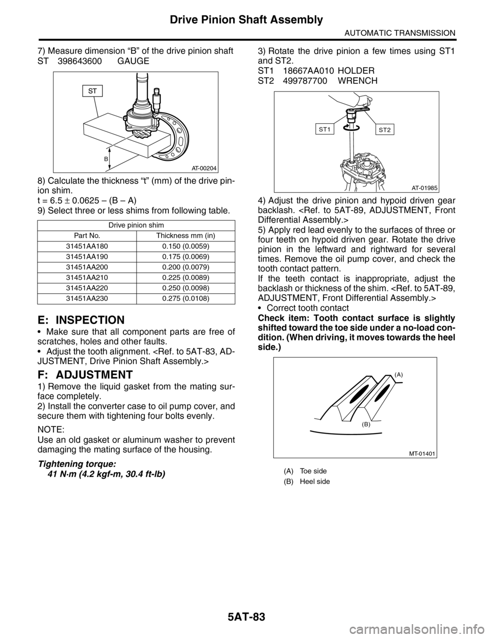
7) Measure dimension “B” of the drive pinion shaft
ST 398643600 GAUGE
8) Calculate the thickness “t” (mm) of the drive pin-
ion shim.
t = 6.5 ± 0.0625 – (B – A)
9) Select three or less shims from following table.
E: INSPECTION
•Make sure that all component parts are free of
scratches, holes and other faults.
•Adjust the tooth alignment.
F: ADJUSTMENT
1) Remove the liquid gasket from the mating sur-
face completely.
2) Install the converter case to oil pump cover, and
secure them with tightening four bolts evenly.
NOTE:
Use an old gasket or aluminum washer to prevent
damaging the mating surface of the housing.
Tightening torque:
41 N·m (4.2 kgf-m, 30.4 ft-lb)
3) Rotate the drive pinion a few times using ST1
and ST2.
ST1 18667AA010 HOLDER
ST2 499787700 WRENCH
4) Adjust the drive pinion and hypoid driven gear
backlash.
5) Apply red lead evenly to the surfaces of three or
four teeth on hypoid driven gear. Rotate the drive
pinion in the leftward and rightward for several
times. Remove the oil pump cover, and check the
tooth contact pattern.
If the teeth contact is inappropriate, adjust the
backlash or thickness of the shim.
•Correct tooth contact
Check item: Tooth contact surface is slightly
shifted toward the toe side under a no-load con-
dition. (When driving, it moves towards the heel
side.)
Drive pinion shim
Par t No. Thickness mm (in)
31451AA180 0.150 (0.0059)
31451AA190 0.175 (0.0069)
31451AA200 0.200 (0.0079)
31451AA210 0.225 (0.0089)
31451AA220 0.250 (0.0098)
31451AA230 0.275 (0.0108)
B
AT-00204
(A) Toe side
(B) Heel side
AT-01985
ST2ST1
MT-01401
(A)
(B)
Page 2100 of 2453
5AT-84
Drive Pinion Shaft Assembly
AUTOMATIC TRANSMISSION
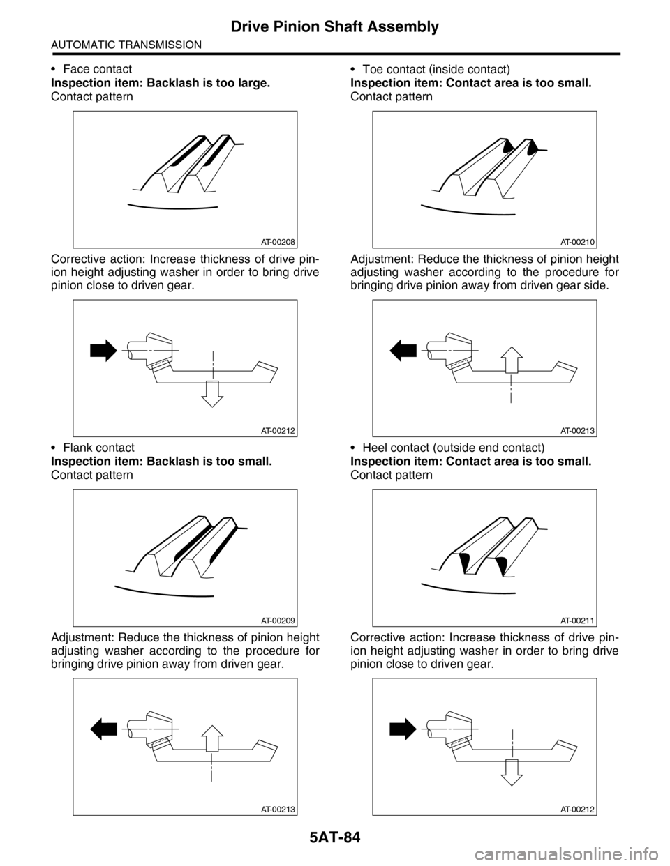
•Face contact
Inspection item: Backlash is too large.
Contact pattern
Corrective action: Increase thickness of drive pin-
ion height adjusting washer in order to bring drive
pinion close to driven gear.
•Flank contact
Inspection item: Backlash is too small.
Contact pattern
Adjustment: Reduce the thickness of pinion height
adjusting washer according to the procedure for
bringing drive pinion away from driven gear.
•Toe contact (inside contact)
Inspection item: Contact area is too small.
Contact pattern
Adjustment: Reduce the thickness of pinion height
adjusting washer according to the procedure for
bringing drive pinion away from driven gear side.
•Heel contact (outside end contact)
Inspection item: Contact area is too small.
Contact pattern
Corrective action: Increase thickness of drive pin-
ion height adjusting washer in order to bring drive
pinion close to driven gear.
AT-00208
AT-00212
AT-00209
AT-00213
AT-00210
AT-00213
AT-00211
AT-00212
Page 2102 of 2453

5AT-86
Front Differential Assembly
AUTOMATIC TRANSMISSION
33.Front Differential Assembly
A: REMOVAL
1) Remove the transmission assembly from vehicle
body.
2) Pull out the torque converter assembly.
3) Remove the transmission harness connector
from stay.
4) Remove the oil charge pipe.
5) Remove the ATF filter inlet and outlet pipes.
6) Separate the converter case from the transmis-
sion case.
7) Remove the differential side retainers using ST.
NOTE:
Hold the differential case assembly by hand to
avoid damaging the retainer mounting hole of the
converter case.
ST 18630AA010 WRENCH COMPL RETAIN-
ER
8) Remove the differential assembly while being
careful not to damage the attachment part of retain-
er.
B: INSTALLATION
1) When installing the differential assembly to
case, be careful not to damage the inside of case
(particularly, the differential side retainer mating
surface).
2) Install the O-ring to left and right side retainer.
3) Using the ST, install the side retainer.
ST 18630AA010 WRENCH COMPL RETAIN-
ER
4) Adjust the backlash of the front differential.
sembly.>
5) Install the lock plate.
Tightening torque:
25 N·m (2.5 kgf-m, 18 ft-lb)
6) Install the converter case to the transmission
case.
7) Install the transmission harness connector to the
stay.
8) Install the ATF filter pipe.
9) Install the oil charge pipe together with an O-
ring.
10) Install the torque converter assembly.
sembly.>
11) Install the transmission assembly to the vehi-
cle.
C: DISASSEMBLY
1. DIFFERENTIAL CASE ASSEMBLY
1) Remove the taper roller bearing using the ST
and a press.
ST 498077000 REMOVER
(A) Differential ASSY
AT-01987
(A)
(A) Lock plate
AT-01988
(A)
AT-00216
Page 2103 of 2453
5AT-87
Front Differential Assembly
AUTOMATIC TRANSMISSION
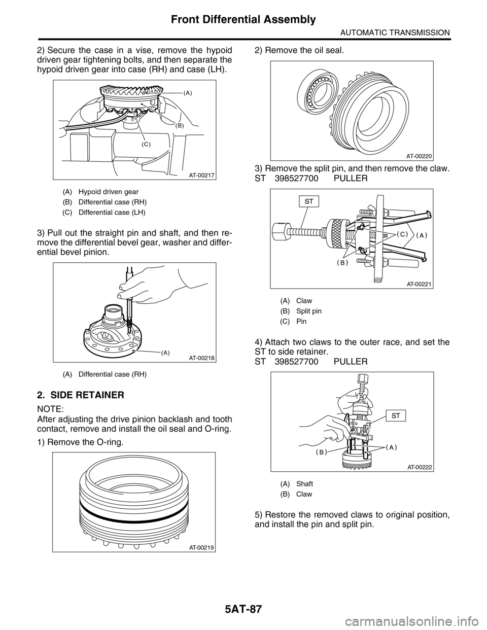
2) Secure the case in a vise, remove the hypoid
driven gear tightening bolts, and then separate the
hypoid driven gear into case (RH) and case (LH).
3) Pull out the straight pin and shaft, and then re-
move the differential bevel gear, washer and differ-
ential bevel pinion.
2. SIDE RETAINER
NOTE:
After adjusting the drive pinion backlash and tooth
contact, remove and install the oil seal and O-ring.
1) Remove the O-ring.
2) Remove the oil seal.
3) Remove the split pin, and then remove the claw.
ST 398527700 PULLER
4) Attach two claws to the outer race, and set the
ST to side retainer.
ST 398527700 PULLER
5) Restore the removed claws to original position,
and install the pin and split pin.
(A) Hypoid driven gear
(B) Differential case (RH)
(C) Differential case (LH)
(A) Differential case (RH)
(B)
AT-00217
(A)
(C)
AT-00218(A)
AT-00219
(A) Claw
(B) Split pin
(C) Pin
(A) Shaft
(B) Claw
AT-00220
AT-00221
AT-00222
Page 2104 of 2453
5AT-88
Front Differential Assembly
AUTOMATIC TRANSMISSION
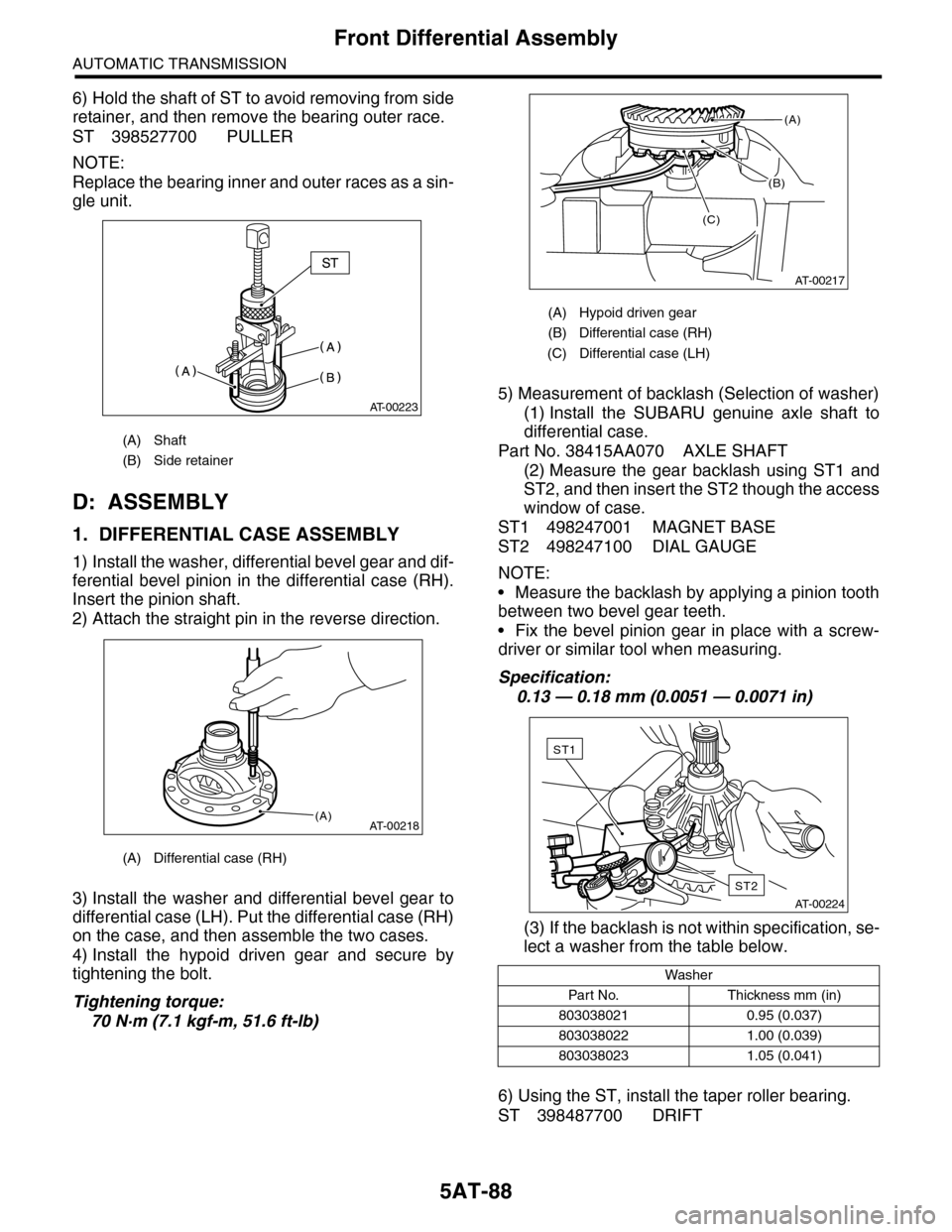
6) Hold the shaft of ST to avoid removing from side
retainer, and then remove the bearing outer race.
ST 398527700 PULLER
NOTE:
Replace the bearing inner and outer races as a sin-
gle unit.
D: ASSEMBLY
1. DIFFERENTIAL CASE ASSEMBLY
1) Install the washer, differential bevel gear and dif-
ferential bevel pinion in the differential case (RH).
Insert the pinion shaft.
2) Attach the straight pin in the reverse direction.
3) Install the washer and differential bevel gear to
differential case (LH). Put the differential case (RH)
on the case, and then assemble the two cases.
4) Install the hypoid driven gear and secure by
tightening the bolt.
Tightening torque:
70 N·m (7.1 kgf-m, 51.6 ft-lb)
5) Measurement of backlash (Selection of washer)
(1) Install the SUBARU genuine axle shaft to
differential case.
Part No. 38415AA070 AXLE SHAFT
(2) Measure the gear backlash using ST1 and
ST2, and then insert the ST2 though the access
window of case.
ST1 498247001 MAGNET BASE
ST2 498247100 DIAL GAUGE
NOTE:
•Measure the backlash by applying a pinion tooth
between two bevel gear teeth.
•Fix the bevel pinion gear in place with a screw-
driver or similar tool when measuring.
Specification:
0.13 — 0.18 mm (0.0051 — 0.0071 in)
(3) If the backlash is not within specification, se-
lect a washer from the table below.
6) Using the ST, install the taper roller bearing.
ST 398487700 DRIFT
(A) Shaft
(B) Side retainer
(A) Differential case (RH)
AT-00223
AT-00218(A)
(A) Hypoid driven gear
(B) Differential case (RH)
(C) Differential case (LH)
Washer
Par t N o. Thickness mm (in)
803038021 0.95 (0.037)
803038022 1.00 (0.039)
803038023 1.05 (0.041)
(B)
AT-00217
(A)
(C)
AT-00224
ST2
ST1
Page 2105 of 2453
5AT-89
Front Differential Assembly
AUTOMATIC TRANSMISSION
2. SIDE RETAINER
NOTE:
Install the oil seal and O-ring of side retainer after
the adjustment of backlash and tooth contact.
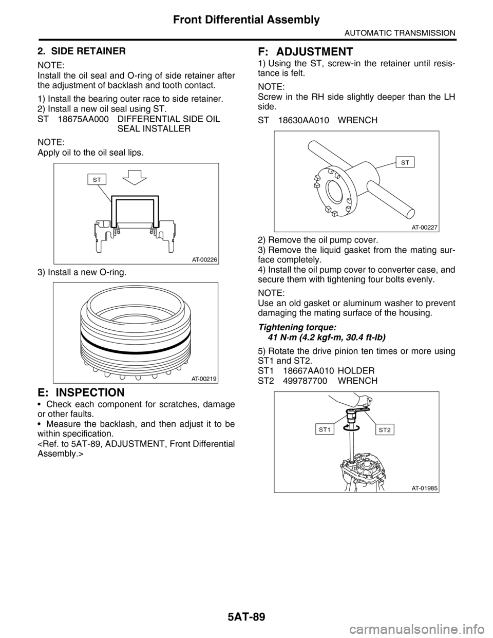
1) Install the bearing outer race to side retainer.
2) Install a new oil seal using ST.
ST 18675AA000 DIFFERENTIAL SIDE OIL
SEAL INSTALLER
NOTE:
Apply oil to the oil seal lips.
3) Install a new O-ring.
E: INSPECTION
•Check each component for scratches, damage
or other faults.
•Measure the backlash, and then adjust it to be
within specification.
F: ADJUSTMENT
1) Using the ST, screw-in the retainer until resis-
tance is felt.
NOTE:
Screw in the RH side slightly deeper than the LH
side.
ST 18630AA010 WRENCH
2) Remove the oil pump cover.
3) Remove the liquid gasket from the mating sur-
face completely.
4) Install the oil pump cover to converter case, and
secure them with tightening four bolts evenly.
NOTE:
Use an old gasket or aluminum washer to prevent
damaging the mating surface of the housing.
Tightening torque:
41 N·m (4.2 kgf-m, 30.4 ft-lb)
5) Rotate the drive pinion ten times or more using
ST1 and ST2.
ST1 18667AA010 HOLDER
ST2 499787700 WRENCH
AT-00226
ST
AT-00219
AT-00227
ST
AT-01985
ST2ST1
Page 2106 of 2453
5AT-90
Front Differential Assembly
AUTOMATIC TRANSMISSION
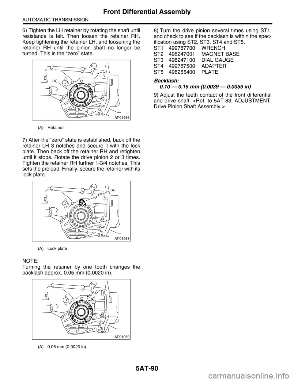
6) Tighten the LH retainer by rotating the shaft until
resistance is felt. Then loosen the retainer RH.
Keep tightening the retainer LH, and loosening the
retainer RH until the pinion shaft no longer be
turned. This is the “zero” state.
7) After the “zero” state is established, back off the
retainer LH 3 notches and secure it with the lock
plate. Then back off the retainer RH and retighten
until it stops. Rotate the drive pinion 2 or 3 times.
Tighten the retainer RH further 1-3/4 notches. This
sets the preload. Finally, secure the retainer with its
lock plate.
NOTE:
Turning the retainer by one tooth changes the
backlash approx. 0.05 mm (0.0020 in).
8) Turn the drive pinion several times using ST1,
and check to see if the backlash is within the spec-
ification using ST2, ST3, ST4 and ST5.
ST1 499787700 WRENCH
ST2 498247001 MAGNET BASE
ST3 498247100 DIAL GAUGE
ST4 499787500 ADAPTER
ST5 498255400 PLATE
Backlash:
0.10 — 0.15 mm (0.0039 — 0.0059 in)
9) Adjust the teeth contact of the front differential
and drive shaft.
(A) Retainer
(A) Lock plate
(A) 0.05 mm (0.0020 in)
AT-01986
(A)
AT-01988
(A)
AT-01989
(A)
Page 2131 of 2453
5AT(diag)-14
Transmission Control Module (TCM) I/O Signal
AUTOMATIC TRANSMISSION (DIAGNOSTICS)
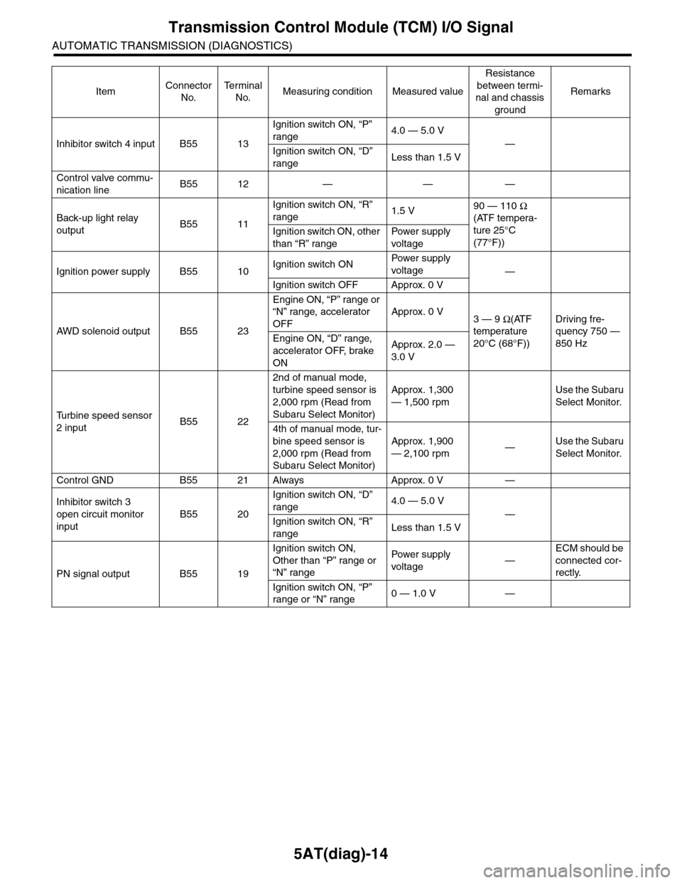
Inhibitor switch 4 input B55 13
Ignition switch ON, “P”
range4.0 — 5.0 V
—
Ignition switch ON, “D”
rangeLess than 1.5 V
Control valve commu-
nication lineB55 12 — — —
Back-up light relay
outputB55 11
Ignition switch ON, “R”
range1.5 V90 — 110 Ω
(ATF tempera-
ture 25°C
(77°F))
Ignition switch ON, other
than “R” range
Pow er s up p ly
voltage
Ignition power supply B55 10Ignition switch ONPow er s up p ly
voltage—
Ignition switch OFF Approx. 0 V
AW D s o le n oi d o u tp u t B 5 5 2 3
Engine ON, “P” range or
“N” range, accelerator
OFF
Approx. 0 V3 — 9 Ω(ATF
temperature
20°C (68°F))
Driving fre-
quency 750 —
850 HzEngine ON, “D” range,
accelerator OFF, brake
ON
Approx. 2.0 —
3.0 V
Tu r b i n e s p e e d s e n s o r
2 inputB55 22
2nd of manual mode,
turbine speed sensor is
2,000 rpm (Read from
Subaru Select Monitor)
Approx. 1,300
— 1,500 rpm
Use the Subaru
Select Monitor.
4th of manual mode, tur-
bine speed sensor is
2,000 rpm (Read from
Subaru Select Monitor)
Approx. 1,900
— 2,100 rpm—Use the Subaru
Select Monitor.
Control GND B55 21 Always Approx. 0 V —
Inhibitor switch 3
open circuit monitor
input
B55 20
Ignition switch ON, “D”
range4.0 — 5.0 V
—
Ignition switch ON, “R”
rangeLess than 1.5 V
PN signal output B55 19
Ignition switch ON,
Other than “P” range or
“N” range
Pow er s up p ly
voltage—
ECM should be
connected cor-
rectly.
Ignition switch ON, “P”
range or “N” range0 — 1.0 V —
ItemConnector
No.
Te r m i n a l
No.Measuring condition Measured value
Resistance
between termi-
nal and chassis
ground
Remarks