2009 SUBARU TRIBECA Back up
[x] Cancel search: Back upPage 1995 of 2453
PM-12
Air Cleaner Element
PERIODIC MAINTENANCE SERVICES
8. Air Cleaner Element
A: REPLACEMENT
1) Disconnect the ground cable from battery.
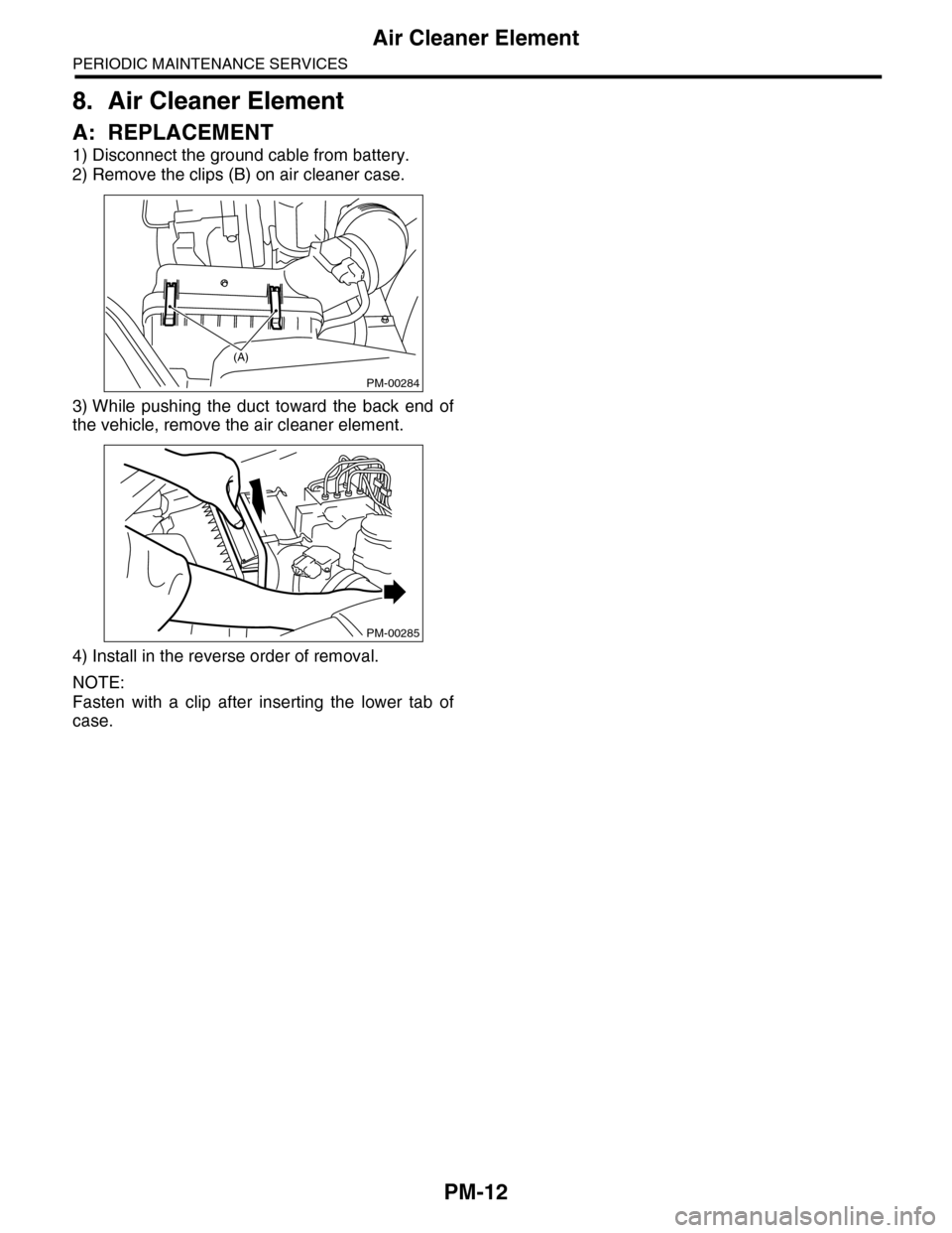
2) Remove the clips (B) on air cleaner case.
3) While pushing the duct toward the back end of
the vehicle, remove the air cleaner element.
4) Install in the reverse order of removal.
NOTE:
Fasten with a clip after inserting the lower tab of
case.
PM-00284
(A)
PM-00285
Page 2005 of 2453
PM-22
Disc Brake Pad & Disc
PERIODIC MAINTENANCE SERVICES
15.Disc Brake Pad & Disc
A: INSPECTION
1) Jack-up the vehicle and support with rigid racks.
Then remove the wheels.
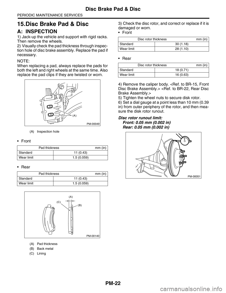
2) Visually check the pad thickness through inspec-
tion hole of disc brake assembly. Replace the pad if
necessary.
NOTE:
When replacing a pad, always replace the pads for
both the left and right wheels at the same time. Also
replace the pad clips if they are twisted or worn.
•Front
•Rear
3) Check the disc rotor, and correct or replace if it is
damaged or worn.
•Front
•Rear
4) Remove the caliper body.
5) Tighten the wheel nuts to secure disk rotor.
6) Set a dial gauge at a point less than 10 mm (0.39
in) from outer periphery of the rotor, and then mea-
sure the disk rotor runout.
Disc rotor runout limit:
Front: 0.05 mm (0.002 in)
Rear: 0.05 mm (0.002 in)
(A) Inspection hole
Pad thickness mm (in)
Standard 11 (0.43)
Wear limit 1.5 (0.059)
Pad thickness mm (in)
Standard 11 (0.43)
Wear limit 1.5 (0.059)
(A) Pad thickness
(B) Back metal
(C) Lining
PM-00049
(A)
PM-00140
(A)
(C)(B)
Disc rotor thickness mm (in)
Standard 30 (1.18)
Wear limit 28 (1.10)
Disc rotor thickness mm (in)
Standard 18 (0.71)
Wear limit 16 (0.63)
PM-00051
Page 2006 of 2453
PM-23
Parking Brake
PERIODIC MAINTENANCE SERVICES
16.Parking Brake
A: INSPECTION
Inspect the brake linings and disc rotor of both
sides of the rear brake at the same time by remov-
ing disc rotor.
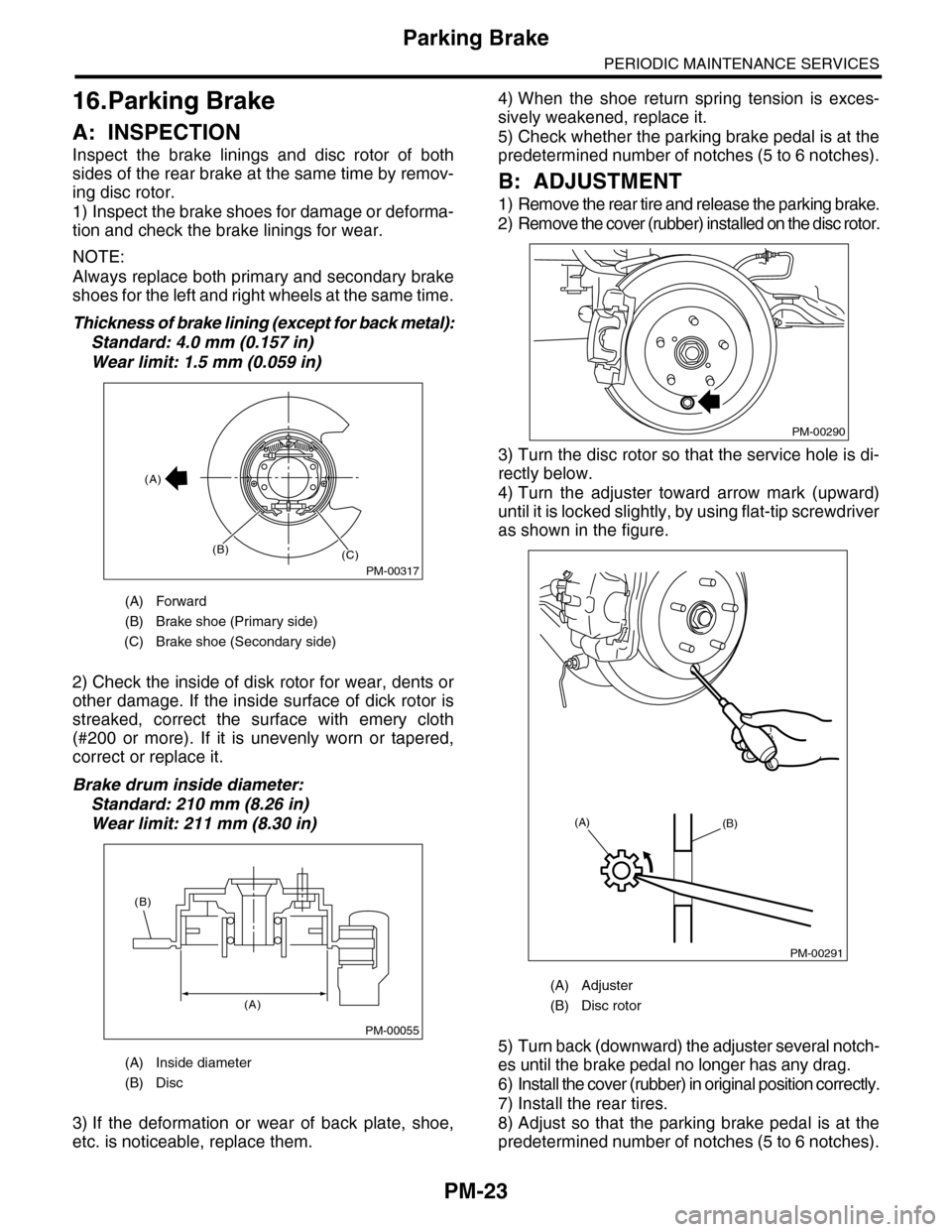
1) Inspect the brake shoes for damage or deforma-
tion and check the brake linings for wear.
NOTE:
Always replace both primary and secondary brake
shoes for the left and right wheels at the same time.
Thickness of brake lining (except for back metal):
Standard: 4.0 mm (0.157 in)
Wear limit: 1.5 mm (0.059 in)
2) Check the inside of disk rotor for wear, dents or
other damage. If the inside surface of dick rotor is
streaked, correct the surface with emery cloth
(#200 or more). If it is unevenly worn or tapered,
correct or replace it.
Brake drum inside diameter:
Standard: 210 mm (8.26 in)
Wear limit: 211 mm (8.30 in)
3) If the deformation or wear of back plate, shoe,
etc. is noticeable, replace them.
4) When the shoe return spring tension is exces-
sively weakened, replace it.
5) Check whether the parking brake pedal is at the
predetermined number of notches (5 to 6 notches).
B: ADJUSTMENT
1) Remove the rear tire and release the parking brake.
2) Remove the cover (rubber) installed on the disc rotor.
3) Turn the disc rotor so that the service hole is di-
rectly below.
4) Turn the adjuster toward arrow mark (upward)
until it is locked slightly, by using flat-tip screwdriver
as shown in the figure.
5) Turn back (downward) the adjuster several notch-
es until the brake pedal no longer has any drag.
6) Install the cover (rubber) in original position correctly.
7) Install the rear tires.
8) Adjust so that the parking brake pedal is at the
predetermined number of notches (5 to 6 notches).
(A) Forward
(B) Brake shoe (Primary side)
(C) Brake shoe (Secondary side)
(A) Inside diameter
(B) Disc
PM-00317
(A)
(B)(C)
PM-00055
(A)
(B)
(A) Adjuster
(B) Disc rotor
PM-00290
PM-00291
(A)(B)
Page 2012 of 2453
PM-29
Steering System (Power Steering)
PERIODIC MAINTENANCE SERVICES
21.Steering System (Power
Steering)
A: INSPECTION
1. STEERING WHEEL
1) Set the steering wheel in a straight-ahead posi-
tion, and check the wheel spokes to make sure
they are correctly set in their specified positions.
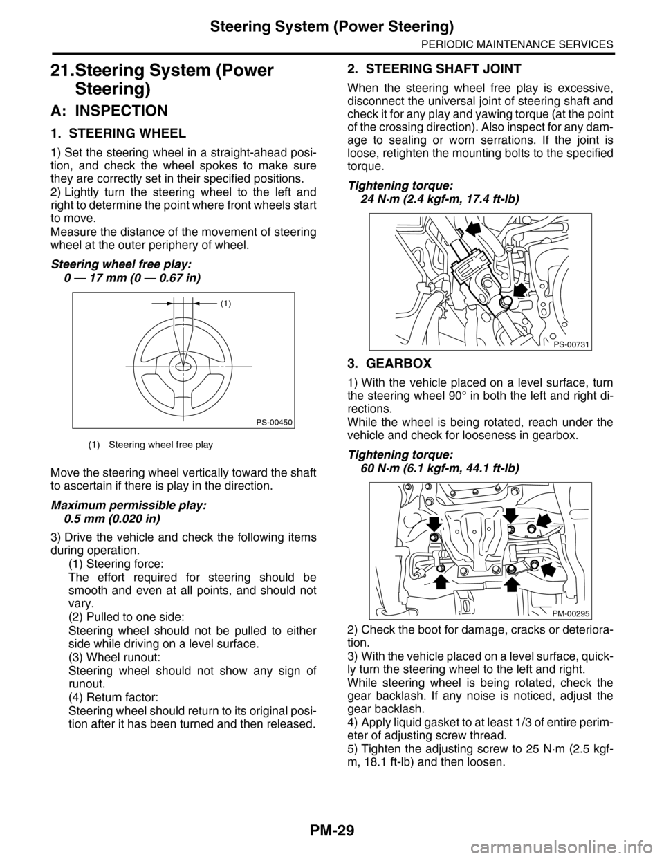
2) Lightly turn the steering wheel to the left and
right to determine the point where front wheels start
to move.
Measure the distance of the movement of steering
wheel at the outer periphery of wheel.
Steering wheel free play:
0 — 17 mm (0 — 0.67 in)
Move the steering wheel vertically toward the shaft
to ascertain if there is play in the direction.
Maximum permissible play:
0.5 mm (0.020 in)
3) Drive the vehicle and check the following items
during operation.
(1) Steering force:
The effort required for steering should be
smooth and even at all points, and should not
vary.
(2) Pulled to one side:
Steering wheel should not be pulled to either
side while driving on a level surface.
(3) Wheel runout:
Steering wheel should not show any sign of
runout.
(4) Return factor:
Steering wheel should return to its original posi-
tion after it has been turned and then released.
2. STEERING SHAFT JOINT
When the steering wheel free play is excessive,
disconnect the universal joint of steering shaft and
check it for any play and yawing torque (at the point
of the crossing direction). Also inspect for any dam-
age to sealing or worn serrations. If the joint is
loose, retighten the mounting bolts to the specified
torque.
Tightening torque:
24 N·m (2.4 kgf-m, 17.4 ft-lb)
3. GEARBOX
1) With the vehicle placed on a level surface, turn
the steering wheel 90° in both the left and right di-
rections.
While the wheel is being rotated, reach under the
vehicle and check for looseness in gearbox.
Tightening torque:
60 N·m (6.1 kgf-m, 44.1 ft-lb)
2) Check the boot for damage, cracks or deteriora-
tion.
3) With the vehicle placed on a level surface, quick-
ly turn the steering wheel to the left and right.
While steering wheel is being rotated, check the
gear backlash. If any noise is noticed, adjust the
gear backlash.
4) Apply liquid gasket to at least 1/3 of entire perim-
eter of adjusting screw thread.
5) Tighten the adjusting screw to 25 N·m (2.5 kgf-
m, 18.1 ft-lb) and then loosen.
(1) Steering wheel free play
(1)
PS-00450
PS-00731
PM-00295
Page 2018 of 2453
5AT-2
General Description
AUTOMATIC TRANSMISSION
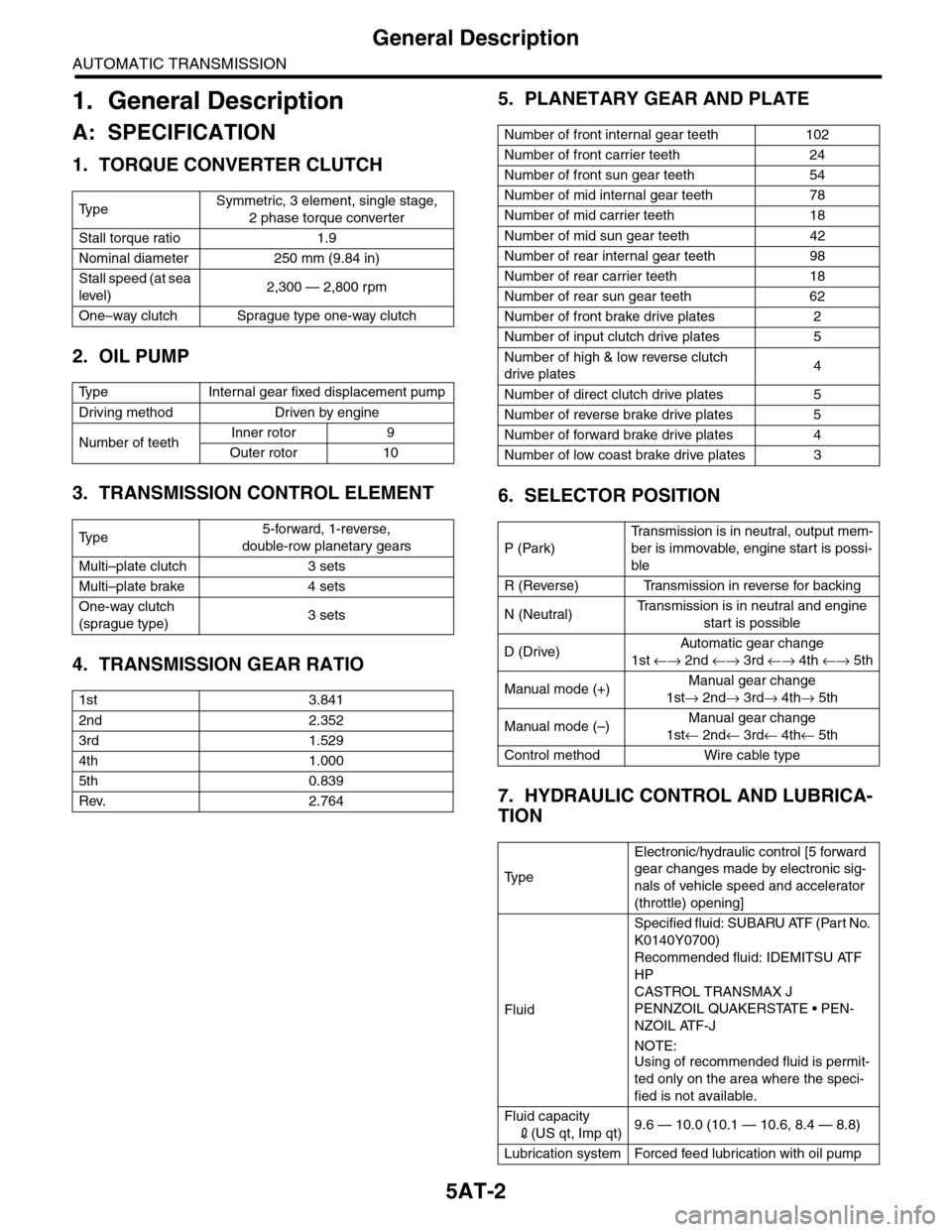
1. General Description
A: SPECIFICATION
1. TORQUE CONVERTER CLUTCH
2. OIL PUMP
3. TRANSMISSION CONTROL ELEMENT
4. TRANSMISSION GEAR RATIO
5. PLANETARY GEAR AND PLATE
6. SELECTOR POSITION
7. HYDRAULIC CONTROL AND LUBRICA-
TION
Ty p eSymmetric, 3 element, single stage,
2 phase torque converter
Stall torque ratio 1.9
Nominal diameter 250 mm (9.84 in)
Stall speed (at sea
level)2,300 — 2,800 rpm
One–way clutch Sprague type one-way clutch
Ty p e I n t e r n a l g e a r f i x e d d i s p l a c e m e n t p u m p
Driving method Driven by engine
Number of teethInner rotor 9
Outer rotor 10
Ty p e5-forward, 1-reverse,
double-row planetary gears
Multi–plate clutch 3 sets
Multi–plate brake 4 sets
One-way clutch
(sprague type)3 sets
1st 3.841
2nd 2.352
3rd 1.529
4th 1.000
5th 0.839
Rev. 2.764
Number of front internal gear teeth 102
Number of front carrier teeth 24
Number of front sun gear teeth 54
Number of mid internal gear teeth 78
Number of mid carrier teeth 18
Number of mid sun gear teeth 42
Number of rear internal gear teeth 98
Number of rear carrier teeth 18
Number of rear sun gear teeth 62
Number of front brake drive plates 2
Number of input clutch drive plates 5
Number of high & low reverse clutch
drive plates4
Number of direct clutch drive plates 5
Number of reverse brake drive plates 5
Number of forward brake drive plates 4
Number of low coast brake drive plates 3
P (Park)
Tr a n s m i s s i o n i s i n n e u t r a l , o u t p u t m e m -
ber is immovable, engine start is possi-
ble
R (Reverse) Transmission in reverse for backing
N (Neutral)Tr a n s m i s s i o n i s i n n e u t r a l a n d e n g i n e
start is possible
D (Drive)Automatic gear change
1st ←→ 2nd ←→ 3rd ←→ 4th ←→ 5th
Manual mode (+)Manual gear change
1st→ 2nd→ 3rd→ 4th→ 5th
Manual mode (–)Manual gear change
1st← 2nd← 3rd← 4th← 5th
Control method Wire cable type
Ty p e
Electronic/hydraulic control [5 forward
gear changes made by electronic sig-
nals of vehicle speed and accelerator
(throttle) opening]
Fluid
Specified fluid: SUBARU ATF (Part No.
K0140Y0700)
Recommended fluid: IDEMITSU ATF
HP
CASTROL TRANSMAX J
PENNZOIL QUAKERSTATE • PEN-
NZOIL ATF-J
NOTE:
Using of recommended fluid is permit-
ted only on the area where the speci-
fied is not available.
Fluid capacity
2(US qt, Imp qt)9.6 — 10.0 (10.1 — 10.6, 8.4 — 8.8)
Lubrication system Forced feed lubrication with oil pump
Page 2036 of 2453
5AT-20
General Description
AUTOMATIC TRANSMISSION
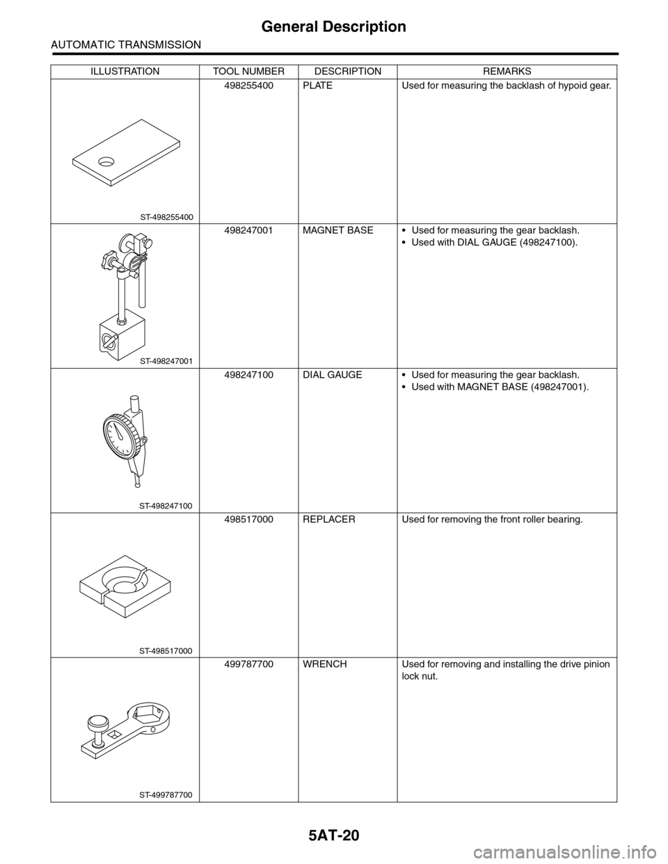
498255400 PLATE Used for measuring the backlash of hypoid gear.
498247001 MAGNET BASE • Used for measuring the gear backlash.
•Used with DIAL GAUGE (498247100).
498247100 DIAL GAUGE • Used for measuring the gear backlash.
•Used with MAGNET BASE (498247001).
498517000 REPLACER Used for removing the front roller bearing.
499787700 WRENCH Used for removing and installing the drive pinion
lock nut.
ILLUSTRATION TOOL NUMBER DESCRIPTION REMARKS
ST-498255400
ST-498247001
ST-498247100
ST-498517000
ST-499787700
Page 2053 of 2453
5AT-37
Automatic Transmission Assembly
AUTOMATIC TRANSMISSION
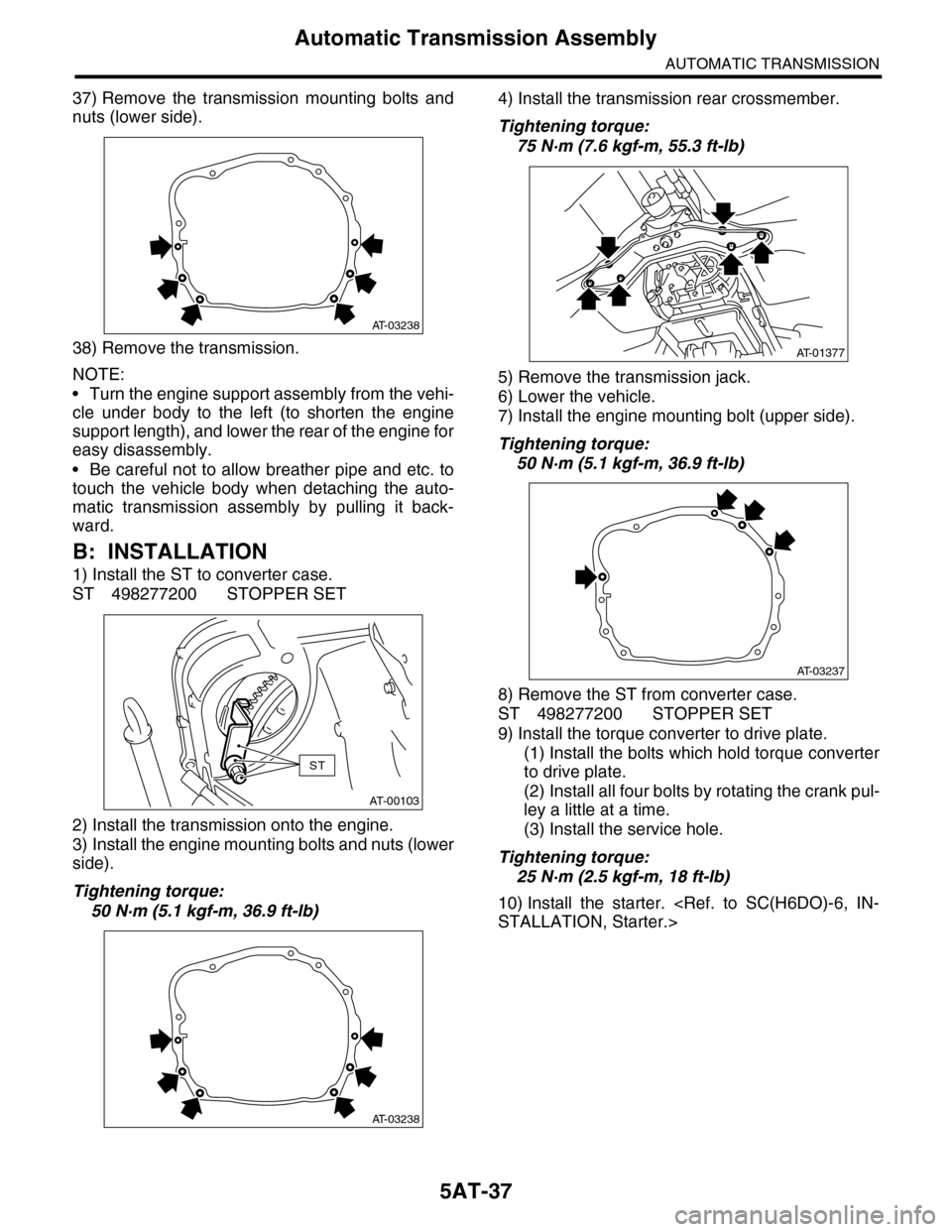
37) Remove the transmission mounting bolts and
nuts (lower side).
38) Remove the transmission.
NOTE:
•Turn the engine support assembly from the vehi-
cle under body to the left (to shorten the engine
support length), and lower the rear of the engine for
easy disassembly.
•Be careful not to allow breather pipe and etc. to
touch the vehicle body when detaching the auto-
matic transmission assembly by pulling it back-
ward.
B: INSTALLATION
1) Install the ST to converter case.
ST 498277200 STOPPER SET
2) Install the transmission onto the engine.
3) Install the engine mounting bolts and nuts (lower
side).
Tightening torque:
50 N·m (5.1 kgf-m, 36.9 ft-lb)
4) Install the transmission rear crossmember.
Tightening torque:
75 N·m (7.6 kgf-m, 55.3 ft-lb)
5) Remove the transmission jack.
6) Lower the vehicle.
7) Install the engine mounting bolt (upper side).
Tightening torque:
50 N·m (5.1 kgf-m, 36.9 ft-lb)
8) Remove the ST from converter case.
ST 498277200 STOPPER SET
9) Install the torque converter to drive plate.
(1) Install the bolts which hold torque converter
to drive plate.
(2) Install all four bolts by rotating the crank pul-
ley a little at a time.
(3) Install the service hole.
Tightening torque:
25 N·m (2.5 kgf-m, 18 ft-lb)
10) Install the starter.
AT-03238
AT-00103
ST
AT-03238
AT-01377
AT-03237
Page 2092 of 2453
5AT-76
Converter Case
AUTOMATIC TRANSMISSION
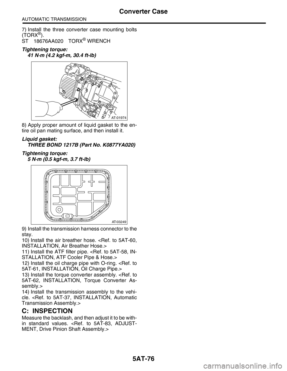
7) Install the three converter case mounting bolts
(TORX®).
ST 18676AA020 TORX® WRENCH
Tightening torque:
41 N·m (4.2 kgf-m, 30.4 ft-lb)
8) Apply proper amount of liquid gasket to the en-
tire oil pan mating surface, and then install it.
Liquid gasket:
THREE BOND 1217B (Part No. K0877YA020)
Tightening torque:
5 N·m (0.5 kgf-m, 3.7 ft-lb)
9) Install the transmission harness connector to the
stay.
10) Install the air breather hose.
11) Install the ATF filter pipe.
12) Install the oil charge pipe with O-ring.
13) Install the torque converter assembly.
sembly.>
14) Install the transmission assembly to the vehi-
cle.
C: INSPECTION
Measure the backlash, and then adjust it to be with-
in standard values.
AT-01974
AT-03249