Page 2270 of 2453

CS-18
AT Shift Lock Control System
CONTROL SYSTEMS
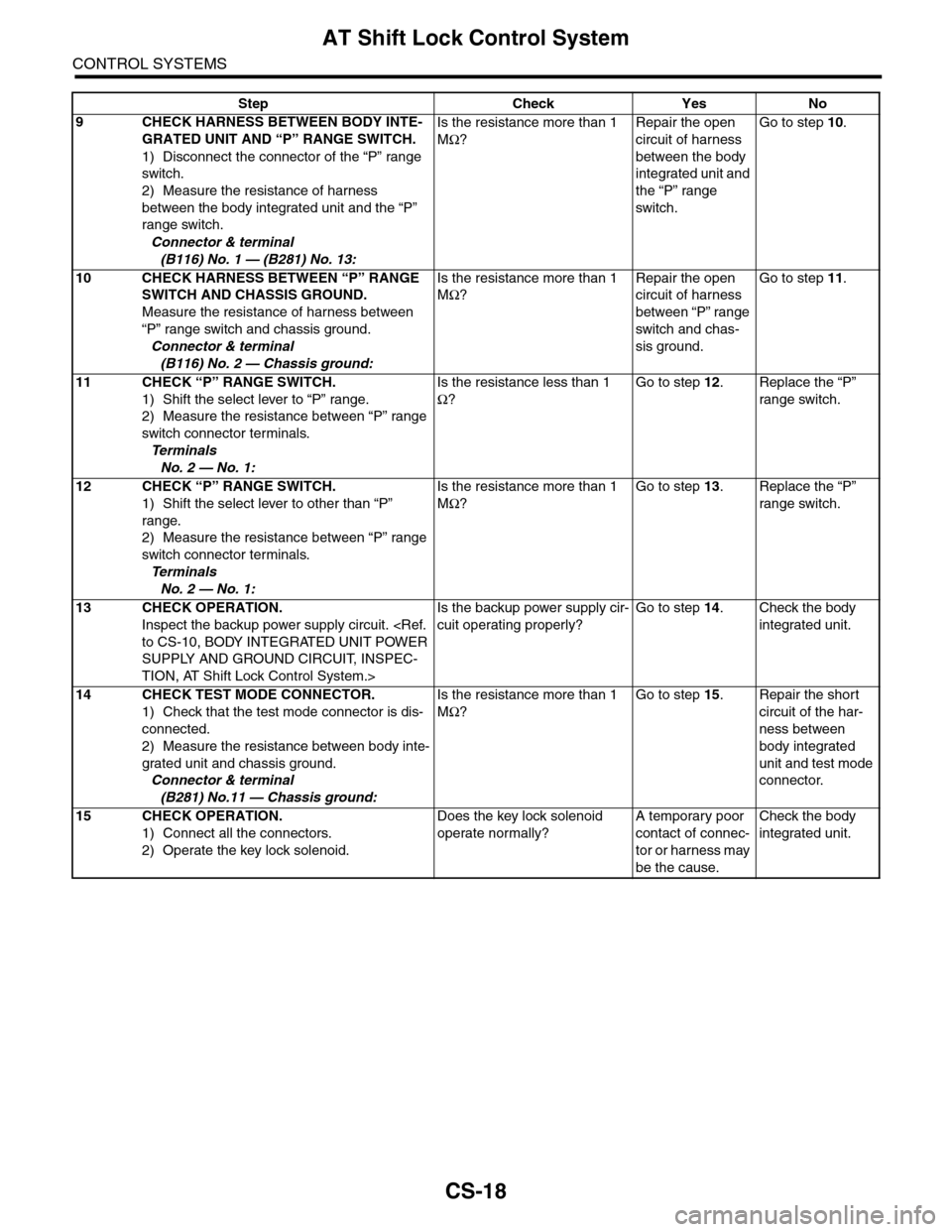
9CHECK HARNESS BETWEEN BODY INTE-
GRATED UNIT AND “P” RANGE SWITCH.
1) Disconnect the connector of the “P” range
switch.
2) Measure the resistance of harness
between the body integrated unit and the “P”
range switch.
Connector & terminal
(B116) No. 1 — (B281) No. 13:
Is the resistance more than 1
MΩ?
Repair the open
circuit of harness
between the body
integrated unit and
the “P” range
switch.
Go to step 10.
10 CHECK HARNESS BETWEEN “P” RANGE
SWITCH AND CHASSIS GROUND.
Measure the resistance of harness between
“P” range switch and chassis ground.
Connector & terminal
(B116) No. 2 — Chassis ground:
Is the resistance more than 1
MΩ?
Repair the open
circuit of harness
between “P” range
switch and chas-
sis ground.
Go to step 11.
11 CHECK “P” RANGE SWITCH.
1) Shift the select lever to “P” range.
2) Measure the resistance between “P” range
switch connector terminals.
Te r m i n a l s
No. 2 — No. 1:
Is the resistance less than 1
Ω?
Go to step 12.Replace the “P”
range switch.
12 CHECK “P” RANGE SWITCH.
1) Shift the select lever to other than “P”
range.
2) Measure the resistance between “P” range
switch connector terminals.
Te r m i n a l s
No. 2 — No. 1:
Is the resistance more than 1
MΩ?
Go to step 13.Replace the “P”
range switch.
13 CHECK OPERATION.
Inspect the backup power supply circuit.
to CS-10, BODY INTEGRATED UNIT POWER
SUPPLY AND GROUND CIRCUIT, INSPEC-
TION, AT Shift Lock Control System.>
Is the backup power supply cir-
cuit operating properly?
Go to step 14.Check the body
integrated unit.
14 CHECK TEST MODE CONNECTOR.
1) Check that the test mode connector is dis-
connected.
2) Measure the resistance between body inte-
grated unit and chassis ground.
Connector & terminal
(B281) No.11 — Chassis ground:
Is the resistance more than 1
MΩ?
Go to step 15.Repair the short
circuit of the har-
ness between
body integrated
unit and test mode
connector.
15 CHECK OPERATION.
1) Connect all the connectors.
2) Operate the key lock solenoid.
Does the key lock solenoid
operate normally?
A temporary poor
contact of connec-
tor or harness may
be the cause.
Check the body
integrated unit.
Step Check Yes No
Page 2272 of 2453

CS-20
Select Lever
CONTROL SYSTEMS
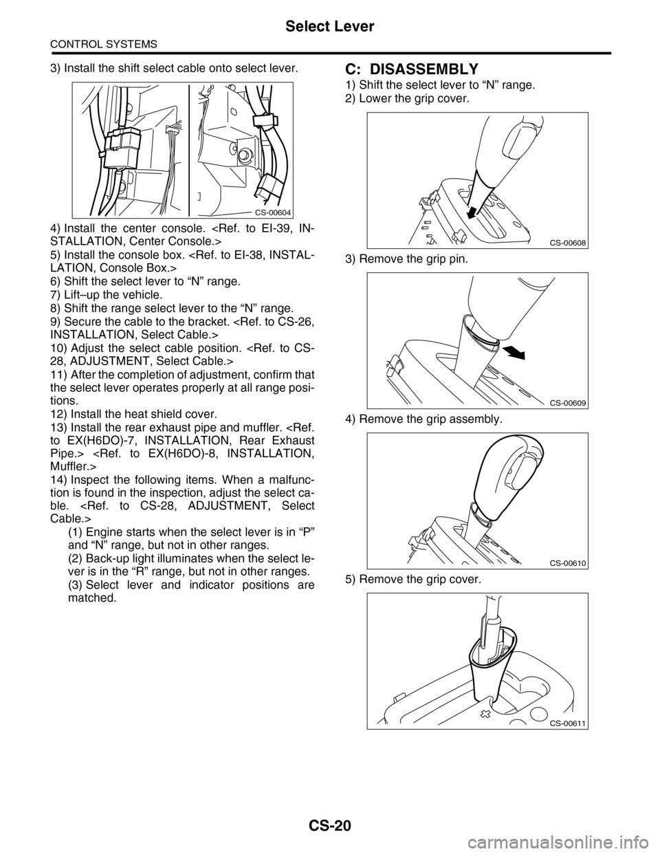
3) Install the shift select cable onto select lever.
4) Install the center console.
STALLATION, Center Console.>
5) Install the console box.
LATION, Console Box.>
6) Shift the select lever to “N” range.
7) Lift–up the vehicle.
8) Shift the range select lever to the “N” range.
9) Secure the cable to the bracket.
INSTALLATION, Select Cable.>
10) Adjust the select cable position.
28, ADJUSTMENT, Select Cable.>
11) After the completion of adjustment, confirm that
the select lever operates properly at all range posi-
tions.
12) Install the heat shield cover.
13) Install the rear exhaust pipe and muffler.
to EX(H6DO)-7, INSTALLATION, Rear Exhaust
Pipe.>
Muffler.>
14) Inspect the following items. When a malfunc-
tion is found in the inspection, adjust the select ca-
ble.
Cable.>
(1) Engine starts when the select lever is in “P”
and “N” range, but not in other ranges.
(2) Back-up light illuminates when the select le-
ver is in the “R” range, but not in other ranges.
(3) Select lever and indicator positions are
matched.
C: DISASSEMBLY
1) Shift the select lever to “N” range.
2) Lower the grip cover.
3) Remove the grip pin.
4) Remove the grip assembly.
5) Remove the grip cover.
CS-00604
CS-00608
CS-00609
CS-00610
CS-00611
Page 2279 of 2453

CS-27
Select Cable
CONTROL SYSTEMS
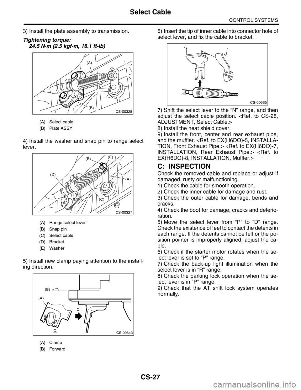
3) Install the plate assembly to transmission.
Tightening torque:
24.5 N·m (2.5 kgf-m, 18.1 ft-lb)
4) Install the washer and snap pin to range select
lever.
5) Install new clamp paying attention to the install-
ing direction.
6) Insert the tip of inner cable into connector hole of
select lever, and fix the cable to bracket.
7) Shift the select lever to the “N” range, and then
adjust the select cable position.
ADJUSTMENT, Select Cable.>
8) Install the heat shield cover.
9) Install the front, center and rear exhaust pipe,
and the muffler.
TION, Front Exhaust Pipe.>
INSTALLATION, Rear Exhaust Pipe.>
EX(H6DO)-8, INSTALLATION, Muffler.>
C: INSPECTION
Check the removed cable and replace or adjust if
damaged, rusty or malfunctioning.
1) Check the cable for smooth operation.
2) Check the inner cable for damage and rust.
3) Check the outer cable for damage, bends and
cracks.
4) Check the boot for damage, cracks and deterio-
ration.
5) Move the select lever from “P” to “D” range.
Check the existence of feel to contact the detents in
each range. If the detents cannot be felt or the po-
sition pointer is improperly aligned, adjust the ca-
ble.
6) Check if the starter motor rotates when the se-
lect lever is set to “P” range.
7) Check the back-up light illumination when the
select lever is in “R” range.
8) Check the parking lock operation when the se-
lect lever is in “P” range.
9) Check that the AT shift lock system operates
normally.
(A) Select cable
(B) Plate ASSY
(A) Range select lever
(B) Snap pin
(C) Select cable
(D) Bracket
(E) Washer
(A) Clamp
(B) Forward
(A)
(B)CS-00328
CS-00327
(B)
(D)
(C)
(E)
(A)
CS-00643
(A)
(B)
C
C
CS-00535
Page 2285 of 2453
CS-33
General Diagnostic Table
CONTROL SYSTEMS
7. General Diagnostic Table
A: INSPECTION
Symptom Possible cause Corrective action
Select Lever Starter does not run. Adjust the select cable, or inspect circuit.
Back-up light does not illuminate. Adjust the select cable, or inspect circuit.
AT s h i f t l o c k s y s t e m d o e s n o t o p e r a t e n o r m a l l y. A d j u s t t h e s e l e c t c a b l e , o r i n s p e c t c i r c u i t .
Will not change to manual or sports mode. Inspect the mode change switch and select lever,
or inspect the circuit.
Up-shift is not engaged at manual mode. Check the shift-up switch and circuit.
Down-shift is not engaged at manual mode. Check the shift-down switch and circuit.
Page 2304 of 2453

WI-20
Power Supply Circuit
WIRING SYSTEM
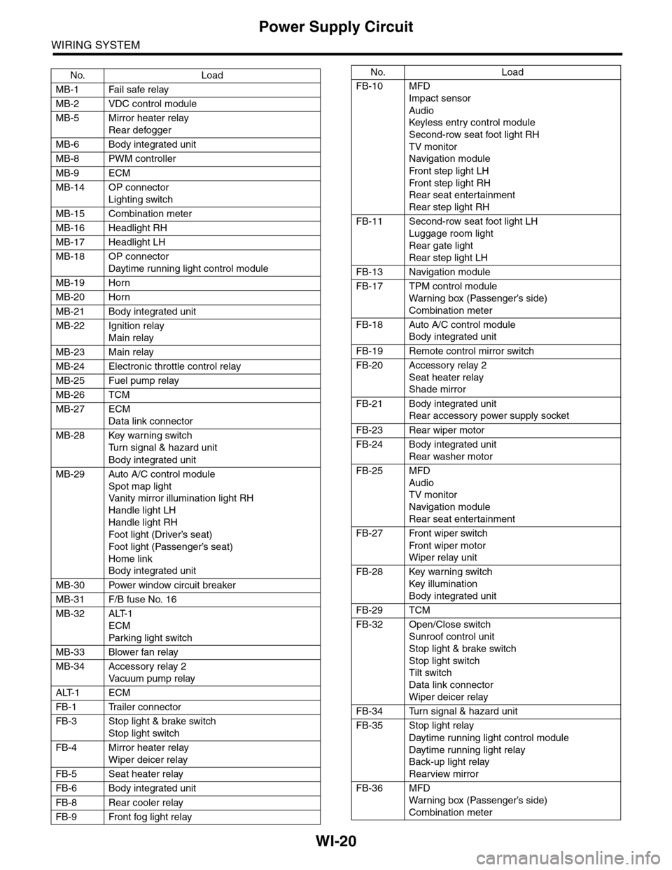
No. Load
MB-1 Fail safe relay
MB-2 VDC control module
MB-5 Mirror heater relay
Rear defogger
MB-6 Body integrated unit
MB-8 PWM controller
MB-9 ECM
MB-14 OP connector
Lighting switch
MB-15 Combination meter
MB-16 Headlight RH
MB-17 Headlight LH
MB-18 OP connector
Daytime running light control module
MB-19 Horn
MB-20 Horn
MB-21 Body integrated unit
MB-22 Ignition relay
Main relay
MB-23 Main relay
MB-24 Electronic throttle control relay
MB-25 Fuel pump relay
MB-26 TCM
MB-27 ECM
Data link connector
MB-28 Key warning switch
Tu r n s i g n a l & h a z a r d u n i t
Body integrated unit
MB-29 Auto A/C control module
Spot map light
Va n i t y m i r r o r i l l u m i n a t i o n l i g h t R H
Handle light LH
Handle light RH
Foot light (Driver’s seat)
Foot light (Passenger’s seat)
Home link
Body integrated unit
MB-30 Power window circuit breaker
MB-31 F/B fuse No. 16
MB-32 ALT-1
ECM
Par king light switch
MB-33 Blower fan relay
MB-34 Accessory relay 2
Va c u u m p u m p r e l ay
ALT-1 ECM
FB-1 Trailer connector
FB-3 Stop light & brake switch
Stop light switch
FB-4 Mirror heater relay
Wiper deicer relay
FB-5 Seat heater relay
FB-6 Body integrated unit
FB-8 Rear cooler relay
FB-9 Front fog light relay
FB-10 MFD
Impact sensor
Audio
Keyless entr y control module
Second-row seat foot light RH
TV monitor
Navigation module
Fr o n t s te p li gh t LH
Fr o n t s te p li gh t RH
Rear seat entertainment
Rear step light RH
FB-11 Second-row seat foot light LH
Luggage room light
Rear gate light
Rear step light LH
FB-13 Navigation module
FB-17 TPM control module
War ning box (Passenger’s side)
Combination meter
FB-18 Auto A/C control module
Body integrated unit
FB-19 Remote control mirror switch
FB-20 Accessory relay 2
Seat heater relay
Shade mirror
FB-21 Body integrated unit
Rear accessory power supply socket
FB-23 Rear wiper motor
FB-24 Body integrated unit
Rear washer motor
FB-25 MFD
Audio
TV monitor
Navigation module
Rear seat entertainment
FB-27 Front wiper switch
Fr o n t wi p er mo t or
Wiper relay unit
FB-28 Key warning switch
Key illumination
Body integrated unit
FB-29 TCM
FB-32 Open/Close switch
Sunroof control unit
Stop light & brake switch
Stop light switch
Tilt switch
Data link connector
Wiper deicer relay
FB-34 Turn signal & hazard unit
FB-35 Stop light relay
Daytime running light control module
Daytime running light relay
Back-up light relay
Rearview mirror
FB-36 MFD
War ning box (Passenger’s side)
Combination meter
No. Load
Page 2311 of 2453
WI-27
Ground Circuit
WIRING SYSTEM
WI-08035
GND-06GND-06
D140B A16
REAR GATE RELEASE
ACTUATOR
GND-05G
GND-05H
BB
GB-12
BBY
GB-13
BBY
GB-15GB-14
D35
12345678910
D139B2
1
B2B4
TAIL LIGHT RH
D134B2
1
TAIL LIGHT LH
D137B2
1
LICENSE PLATE LIGHT RH
D44B2
1
LICENSE PLATE LIGHT LH
D37B2
1
LUGGAGE ROOM LIGHT
D39B
HIGH-MOUNTED STOP LIGHT
D87B2
1
BACK UP LIGHT RH
D91B2
1
BACK UP LIGHT LH
D43B2
3
REAR WIPER MOTOR
D135B2
1
REAR GATE LATCH SWITCH
D89B2
2
REAR DEFOGGER
R79B
TRAILER CONNECTOR
D34
R37
B
2
B
26
R26B3
REAR COMBINATION LIGHT RH
R28B3
REAR COMBINATIONLIGHT LH
2
BB8
D35R39
BB12
R215R247
D39
12D139
D134D44
D91
D135
D87D137D140
D43
121234
D34
D89
121
R215
12
10115634897131412
12
D37
123
R26
R28
4321
R79
123456
Page 2334 of 2453
WI-50
AT Control System
WIRING SYSTEM
7. AT Control System
A: WIRING DIAGRAM
WI-08056
BATTERY
TCM
M/B FUSE NO. 12F/B FUSE NO. 4
SBFSBF-8
SBF-6
IG 2RELAY
P-VIGN RELAY
IGNITION SWITCHOFF+B
ACC
ACCONST
ST
DATA LINK CONNECTOR
A20B2B1
B10
A1
A7
A8
A10
B15
B19
B11
COMBINATION METER
DIMMER & STABILIZING
POWER CIRCUIT
LCD(RANGE POSITION/GEAR POSITION)
I/F
MICRO COMPUTER
DRIVER
BODY INTEGRATED UNITCAN TRANSCEIVER &RECEIVER
AT SELECT LEVER
BACK-UP LIGHT RELAY
BACK-UP LIGHT
M/B FUSE NO. 13F/B FUSE NO. 18F/B FUSE NO. 5
F/B FUSE NO. 33
F/B FUSE NO. 12F/B FUSE NO. 31
AW D WA R N I N GLIGHT
SPORTINDICATORLIGHT
AT OILTEMPERATUREWA R N I N GLIGHT
TWISTEDPAIR LINE
A3A4
CAN JOINTCONNECTOR
VDCCONTROLMODULE
ECM
CAN JOINTCONNECTOR
CAN JOINTCONNECTOR
STEERINGANGLESENSOR
YAWRATESENSOR
IG2
IG1
Page 2339 of 2453
WI-55
AT Control System
WIRING SYSTEM
WI-08061
5AT-045AT-04
A:B54B55B:(GRAY)(BLACK)
(BLACK)
YRYRGL
TO POWER SUPPLY CIRCUIT
GR
OrB
A7
OrB
A8
BL
A10
GR
B1
GR
B10
BrR
B11
YR
A1
YR
B2
B54A:B55B:
GL
1
GL
4
MB-26M/B FUSE NO. 12(B)
FB-29F/B FUSE NO. 31(ACC)
FB-38F/B FUSE NO. 12(IG)
FB-35F/B FUSE NO. 18(IG)
TCM
REF. TO BACK-UPLIGHT SYSTEM[BACK/L-01]
BrR
2
BrY
3
BACK-UP LIGHTRELAY
B356
GR
2
GR
3
BL
1
OrB
4
P-VIGNRELAY
B357
B357
B356
34
12
123410 11 1219 20 21135614 1578916 17 1822 23 24
12 7 8 9563410 11 1219 20 2113 14 15 16 17 1822 23 24