Page 1481 of 2453
EN(H6DO)(diag)-320
Diagnostic Procedure with Diagnostic Trouble Code (DTC)
ENGINE (DIAGNOSTICS)
DM:DTC P2088 OCV SOLENOID VALVE SIGNAL A CIRCUIT OPEN (BANK 1)
DTC DETECTING CONDITION:
•Immediately at fault recognition
•GENERAL DESCRIPTION
CIRCUIT OPEN (BANK 1), Diagnostic Trouble Code (DTC) Detecting Criteria.>
TROUBLE SYMPTOM:
Erroneous idling
CAUTION:
After repair or replacement of faulty parts, perform Clear Memory Mode
OPERATION, Clear Memory Mode.> and Inspection Mode
Inspection Mode.>.
WIRING DIAGRAM:
EN-03669
B21
E2
B137
E67
16
21
2423
E67
12
17
ECM
B21
123412131415567816171819910 1120212223 24 25 2627 28 29 3031 32 33
3534 37363938 41404342 4445 47464948 51505352 54
OIL FLOW CONTROL SOLENOID VALVE RH
B137
85610 11 12 13 14 157213416
3019 20 2228 29
91718 2521 23 243126 27
Page 1483 of 2453
EN(H6DO)(diag)-322
Diagnostic Procedure with Diagnostic Trouble Code (DTC)
ENGINE (DIAGNOSTICS)
DN:DTC P2089 OCV SOLENOID VALVE SIGNAL A CIRCUIT SHORT (BANK 1)
DTC DETECTING CONDITION:
•Immediately at fault recognition
•GENERAL DESCRIPTION
CIRCUIT SHORT (BANK 1), Diagnostic Trouble Code (DTC) Detecting Criteria.>
TROUBLE SYMPTOM:
Erroneous idling
CAUTION:
After repair or replacement of faulty parts, perform Clear Memory Mode
OPERATION, Clear Memory Mode.> and Inspection Mode
Inspection Mode.>.
WIRING DIAGRAM:
EN-03669
B21
E2
B137
E67
16
21
2423
E67
12
17
ECM
B21
123412131415567816171819910 1120212223 24 25 2627 28 29 3031 32 33
3534 37363938 41404342 4445 47464948 51505352 54
OIL FLOW CONTROL SOLENOID VALVE RH
B137
85610 11 12 13 14 157213416
3019 20 2228 29
91718 2521 23 243126 27
Page 1485 of 2453
EN(H6DO)(diag)-324
Diagnostic Procedure with Diagnostic Trouble Code (DTC)
ENGINE (DIAGNOSTICS)
DO:DTC P2092 OCV SOLENOID VALVE SIGNAL A CIRCUIT OPEN (BANK 2)
DTC DETECTING CONDITION:
•Immediately at fault recognition
•GENERAL DESCRIPTION
CIRCUIT OPEN (BANK 2), Diagnostic Trouble Code (DTC) Detecting Criteria.>
TROUBLE SYMPTOM:
Erroneous idling
CAUTION:
After repair or replacement of faulty parts, perform Clear Memory Mode
OPERATION, Clear Memory Mode.> and Inspection Mode
Inspection Mode.>.
WIRING DIAGRAM:
EN-03670
B21
E2
B137
E68
14
21
2827
E68
12
15
ECM
B21
123412131415567816171819910 1120212223 24 25 2627 28 29 3031 32 33
3534 37363938 41404342 4445 47464948 51505352 54
OIL FLOW CONTROLSOLENOID VALVE LH
B137
85610 11 12 13 14 157213416
3019 20 2228 29
91718 2521 23 243126 27
Page 1487 of 2453
EN(H6DO)(diag)-326
Diagnostic Procedure with Diagnostic Trouble Code (DTC)
ENGINE (DIAGNOSTICS)
DP:DTC P2093 OCV SOLENOID VALVE SIGNAL A CIRCUIT SHORT (BANK 2)
DTC DETECTING CONDITION:
•Immediately at fault recognition
•GENERAL DESCRIPTION
CIRCUIT SHORT (BANK 2), Diagnostic Trouble Code (DTC) Detecting Criteria.>
TROUBLE SYMPTOM:
Erroneous idling
CAUTION:
After repair or replacement of faulty parts, perform Clear Memory Mode
OPERATION, Clear Memory Mode.> and Inspection Mode
Inspection Mode.>.
WIRING DIAGRAM:
EN-03670
B21
E2
B137
E68
14
21
2827
E68
12
15
ECM
B21
123412131415567816171819910 1120212223 24 25 2627 28 29 3031 32 33
3534 37363938 41404342 4445 47464948 51505352 54
OIL FLOW CONTROLSOLENOID VALVE LH
B137
85610 11 12 13 14 157213416
3019 20 2228 29
91718 2521 23 243126 27
Page 1553 of 2453

EN(H6DO)(diag)-392
General Diagnostic Table
ENGINE (DIAGNOSTICS)
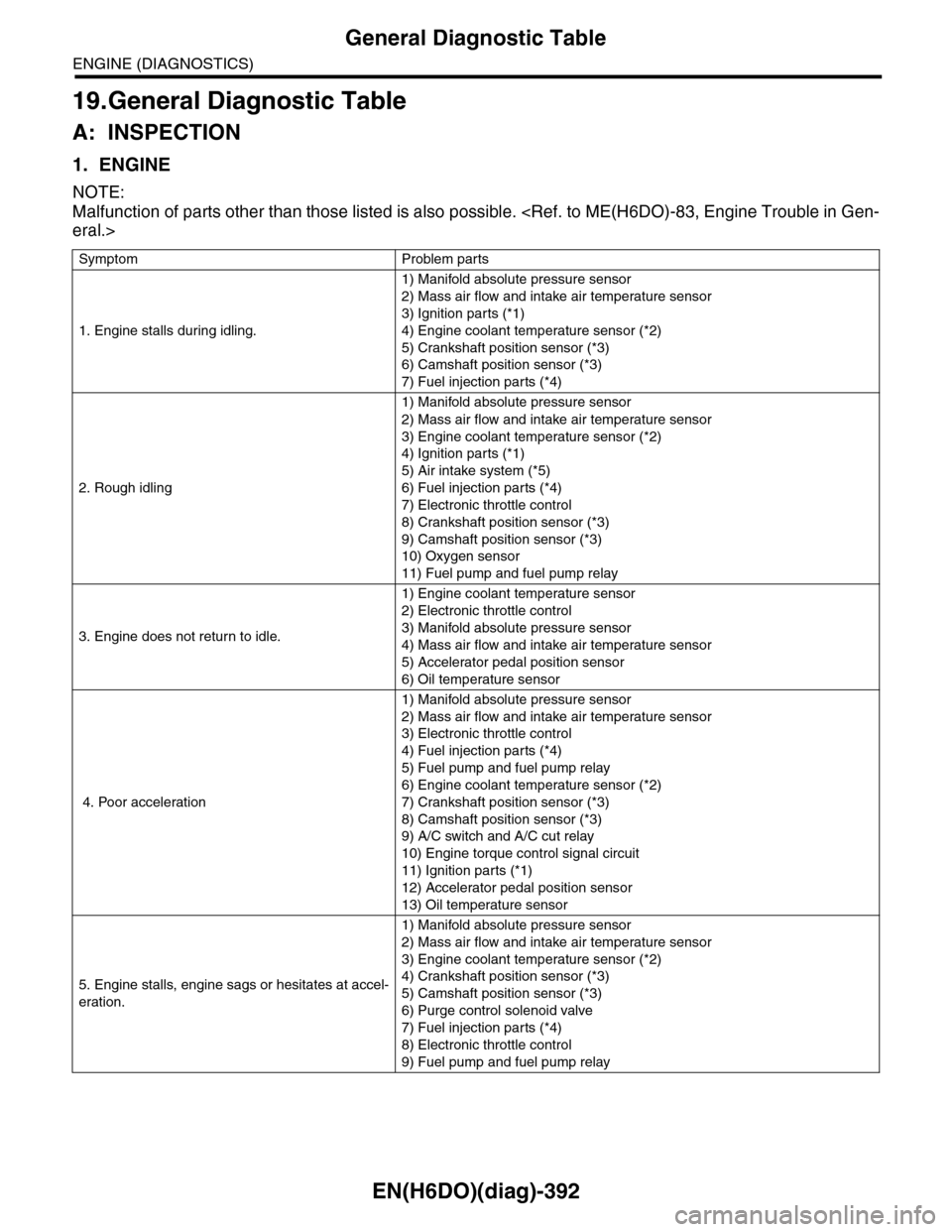
19.General Diagnostic Table
A: INSPECTION
1. ENGINE
NOTE:
Malfunction of parts other than those listed is also possible.
eral.>
Symptom Problem parts
1. Engine stalls during idling.
1) Manifold absolute pressure sensor
2) Mass air flow and intake air temperature sensor
3) Ignition parts (*1)
4) Engine coolant temperature sensor (*2)
5) Crankshaft position sensor (*3)
6) Camshaft position sensor (*3)
7) Fuel injection parts (*4)
2. Rough idling
1) Manifold absolute pressure sensor
2) Mass air flow and intake air temperature sensor
3) Engine coolant temperature sensor (*2)
4) Ignition parts (*1)
5) Air intake system (*5)
6) Fuel injection parts (*4)
7) Electronic throttle control
8) Crankshaft position sensor (*3)
9) Camshaft position sensor (*3)
10) Oxygen sensor
11) Fuel pump and fuel pump relay
3. Engine does not return to idle.
1) Engine coolant temperature sensor
2) Electronic throttle control
3) Manifold absolute pressure sensor
4) Mass air flow and intake air temperature sensor
5) Accelerator pedal position sensor
6) Oil temperature sensor
4. Poor acceleration
1) Manifold absolute pressure sensor
2) Mass air flow and intake air temperature sensor
3) Electronic throttle control
4) Fuel injection parts (*4)
5) Fuel pump and fuel pump relay
6) Engine coolant temperature sensor (*2)
7) Crankshaft position sensor (*3)
8) Camshaft position sensor (*3)
9) A/C switch and A/C cut relay
10) Engine torque control signal circuit
11) Ignition parts (*1)
12) Accelerator pedal position sensor
13) Oil temperature sensor
5. Engine stalls, engine sags or hesitates at accel-
eration.
1) Manifold absolute pressure sensor
2) Mass air flow and intake air temperature sensor
3) Engine coolant temperature sensor (*2)
4) Crankshaft position sensor (*3)
5) Camshaft position sensor (*3)
6) Purge control solenoid valve
7) Fuel injection parts (*4)
8) Electronic throttle control
9) Fuel pump and fuel pump relay
Page 1554 of 2453

EN(H6DO)(diag)-393
General Diagnostic Table
ENGINE (DIAGNOSTICS)
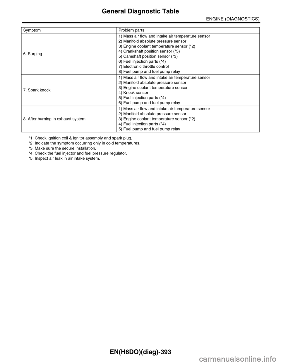
*1: Check ignition coil & ignitor assembly and spark plug.
*2: Indicate the symptom occurring only in cold temperatures.
*3: Make sure the secure installation.
*4: Check the fuel injector and fuel pressure regulator.
*5: Inspect air leak in air intake system.
6. Surging
1) Mass air flow and intake air temperature sensor
2) Manifold absolute pressure sensor
3) Engine coolant temperature sensor (*2)
4) Crankshaft position sensor (*3)
5) Camshaft position sensor (*3)
6) Fuel injection parts (*4)
7) Electronic throttle control
8) Fuel pump and fuel pump relay
7. Spark knock
1) Mass air flow and intake air temperature sensor
2) Manifold absolute pressure sensor
3) Engine coolant temperature sensor
4) Knock sensor
5) Fuel injection parts (*4)
6) Fuel pump and fuel pump relay
8. After burning in exhaust system
1) Mass air flow and intake air temperature sensor
2) Manifold absolute pressure sensor
3) Engine coolant temperature sensor (*2)
4) Fuel injection parts (*4)
5) Fuel pump and fuel pump relay
Symptom Problem parts
Page 1837 of 2453
IG(H6DO)-2
General Description
IGNITION
1. General Description
A: SPECIFICATION
Item Specification
Ignition coil & ignitor ASSY
Typ e F K 0 14 0
Ignition system Independent ignition coil
Manufacturer Diamond Electric
Spar k p l ug
Manufacturer and type NGK: ILFR6B
Thread size (diameter, pitch, length) mm 14, 1.25, 26.5
Spark plug gap mm (in) 0.7 — 0.8 (0.028 — 0.031)
Electrode Iridium
Page 1838 of 2453
IG(H6DO)-3
General Description
IGNITION
B: COMPONENT
C: CAUTION
•Wear work clothing, including a cap, protective goggles and protective shoes during operation.
•Remove contamination including dirt and corrosion before removal, installation or disassembly.
•Keep the disassembled parts in order and protect them from dust and dirt.
•Before removal, installation or disassembly, be sure to clarify the failure. Avoid unnecessary removal, in-
stallation, disassembly and replacement.
•Be careful not to burn yourself, because each part on the vehicle is hot after running.
•Be sure to tighten fasteners including bolts and nuts to the specified torque.
•Place shop jacks or rigid racks at the specified points.
•Before disconnecting connectors of sensors or units, be sure to disconnect the ground cable from battery.
(1) Spark plug Tightening torque: N·m (kgf-m, ft-lb)
(2) Ignition coil & ignitor ASSY T1: 16 (1.6, 11.7)
T2: 21 (2.1, 15.2)
IG-00052
(1)
(1)
(2)
(2)
T1
T2
T2
T1