2009 SUBARU TRIBECA Oil spec
[x] Cancel search: Oil specPage 932 of 2453

PS-52
General Diagnostic Table
POWER ASSISTED SYSTEM (POWER STEERING)
2. MEASUREMENT OF STEERING EFFORT
Step Check Yes No
1CHECK STEERING EFFORT.
1) Stop the vehicle on paved road.
2) Start the engine.
3) Run the engine at idle.
4) Install a spring scale on the steering wheel.
5) Pull the spring scale at a right angle to the
steering wheel, and measure both right and left
steering wheel efforts.
NOTE:When turning the steering more quickly than
necessary from a direction to the other direction
at an engine speed over 2,000 rpm, steering ef-
fort may be heavy. This is caused by flow char-
acteristic of the fluid in the oil pump and is not a
defect.
Is the steering effort less than
29.4 N (3.0 kgf, 6.6 lb)?
Go to step 2.Adjust the back-
lash.
2CHECK STEERING EFFORT.
1) Stop the engine.
2) Pull the spring scale at a right angle to the
steering wheel, and measure both right and left
steering wheel efforts.
Is the steering effort less than
294.2 N (30 kgf, 66.2 lb)?
Go to step 3.Perform the
adjustment.
3CHECK STEERING WHEEL EFFORT.
1) Remove the universal joint.
2) Measure the steering wheel effort.
Is steering effort less than 2.26
N (0.23 kgf, 0.51 lb)?
Go to step 4.Check, adjust and
replace if neces-
sary.
4CHECK STEERING WHEEL EFFORT.
Measure the steering wheel effort.
Is the difference of steering
effort between right and left
less than 20%?
Go to step 5.Check, adjust and
replace if neces-
sary.
5CHECK UNIVERSAL JOINT.
Measure the swing torque of the joint (yoke of
steering column side).
Is the swing torque of the uni-
versal joint less than 7.3 N
(0.74 kgf, 1.64 lb)?
Go to step 6.Replace with a
new part.
6CHECK UNIVERSAL JOINT.
Measure the swing torque of the joint (yoke of
gearbox side).
Is the swing torque of the uni-
versal joint less than 3.8 N
(0.39 kgf, 0.86 lb)?
Go to step 7.Replace with a
new part.
7CHECK FRONT WHEEL.
Check the front wheels.
Does the front wheels have
unsteady revolution or rattling,
or does the brake drag?
Inspect, readjust
and replace if nec-
essary.
Go to step 8.
8CHECK TIE–ROD ENDS.
Remove the tie–rod ends.
If the tie-rod ends of suspen-
sion have unsteady revolution
or rattling?
Inspect and
replace if neces-
sary.
Go to step 9.
9BALL JOINT CHECK.
Remove the ball joint.
If the ball joints of suspension
have unsteady revolution or
rattling?
Inspect and
replace if neces-
sary.
Go to step 10.
10 CHECK GEARBOX.
Measure the rotating of gearbox.
box.>
Is the rotating resistance of
steering gearbox less than
10.5 N (1.1 kgf, 2.4 lb)? Is the
difference between right and
left sides less than 20%?
Go to step 11.Readjust the back-
lash, and if ineffec-
tive, replace the
faulty par ts.
11 CHECK GEARBOX.
Measure the sliding of gearbox.
Is the sliding resistance of
steering gearbox less than 400
N (41 kgf, 90 lb)? Is the differ-
ence between the right and left
sliding resistance less than
20%?
Steering effort is
normal.
Readjust the back-
lash, and if ineffec-
tive, replace the
faulty par ts.
Page 933 of 2453

PS-53
General Diagnostic Table
POWER ASSISTED SYSTEM (POWER STEERING)
3. INSPECTION OF CLEARANCE
This table lists various clearances that must be correctly adjusted to ensure the normal vehicle driving with-
out interfering noise, or any other faults.
Install locations Minimum allowance mm (in)
(1) Crossmember-to-Hose assembly 10 (0.39)
(2) Front frame side-to-Hose assembly 15 (0.59)
(3) Air bag sensor to cooler pipe assembly 10 (0.39)
(4) Air cleaner case-to-Suction hose 10 (0.39)
(5) VDCH/U to Reservoir tank bracket 10 (0.39)
(6) Air boots to Hose clip15 (0.59)
(7) Air boot-to-Hose assembly15 (0.59)
(8) Protector to Hose assembly10 (0.39)
(9) Intake manifold to Suction hose 10 (0.39)
(10) Intake manifold to hose assembly 10 (0.39)
(11) Air cleaner case to Cooler pipe joint block 5 (0.20)
(12) Chain cover to Cooler pipe joint block 20 (0.79)
(13) Oil pipe to Cooler pipe joint block 20 (0.79)
(14) Suction hose to Hose assembly 10 (0.39)
(15) Air boot to Reservoir tank10 (0.39)
(16) Brake pipe to Reservoir tank10 (0.39)
(17) Harness to Hose assembly10 (0.39)
(18) Relay box to Hose assembly15 (0.59)
(19) Bumper beam to Cooler pipe assembly 10 (0.39)
(20) Radiator bracket to Cooler pipe assembly 10 (0.39)
(21) ATF cooler to Cooler pipe assembly 10 (0.39)
(22) Undercover to cooler pipe assembly 10 (0.39)
(23) Protector to Hose assembly10 (0.39)
(24) Protector to Hose assembly15 (0.59)
(25) Return hose to Hose assembly 10 (0.39)
(26) Air cleaner case to Hose assembly 10 (0.39)
(27) Suction hose to Hose assembly 10 (0.39)
(28) Air cleaner case to Return hose 3 (0.12)
(29) Valve housing to DOJ12 (0.47)
(30) Valve housing to Crossmember 1 (0.04)
(31) Mount to Crossmember There must be no contact.
(32) Feed tube to Crossmember3 (0.12)
(33) Elbow to Crossmember3 (0.12)
(34) Cylinder pipe to Crossmember 3 (0.12)
(35) Feed tube to Exhaust pipe18 (0.71)
(36) Tie-rod end to Brake dust cover 2.5 (0.10)
(37) Coupling rubber to AT level gage 10 (0.39)
(38) Yoke to Brake booster5 (0.20)
Page 937 of 2453

RS-4
General Description
REAR SUSPENSION
2. SHOCK ABSORBER
C: CAUTION
Please understand and adhere to the following general precautions. They must be strictly followed to avoid
any injury to the person performing the work or persons in the area.
1. OPERATION
•Wear work clothing, including a cap, protective goggles and protective shoes during operation.
•Before disposing of shock absorbers, be sure to bleed the gas out completely. Also, do not expose to
flames or fire.
•Before removal, installation or disassembly, be sure to clarify the failure. Avoid unnecessary removal, in-
stallation, disassembly and replacement.
•Use SUBARU genuine grease etc. or equivalent. Do not mix grease etc. with that of another grade or from
other manufacturers.
•Before securing a part on a vise, place cushioning material such as wood blocks, aluminum plate, or cloth
between the part and the vise.
•Be sure to tighten fasteners including bolts and nuts to the specified torque.
•Place shop jacks or rigid racks at the specified points.
2. OIL
When handling oil, follow the rules below to prevent unexpected accidents.
•Prepare container and waste cloths when performing work which oil could possibly spill. If oil spills, wipe
it off immediately to prevent from penetrating into floor or flowing outside, for environmental protection.
•Follow all government regulations concerning disposal of refuse when disposing.
(1) Mount (5) Shock absorberTightening torque: N·m (kgf-m, ft-lb)
(2) Upper rubber sheet (6) Self–locking nutT1: 30 (3.1, 22.4)
(3) Dust cover T2: 35 (3.6, 26)
(4) Coil spring T3: 120 (12.2, 89)
Page 946 of 2453

RS-13
Rear Shock Absorber
REAR SUSPENSION
F: DISPOSAL
CAUTION:
•Before handling the shock absorber, be sure
to wear goggles to protect eyes from gas, oil
and cutting powder.
•Do not disassemble the shock absorber or
place it into a fire.
•Drill a hole into shock absorbers in case of
discarding shock absorbers filled with gas.
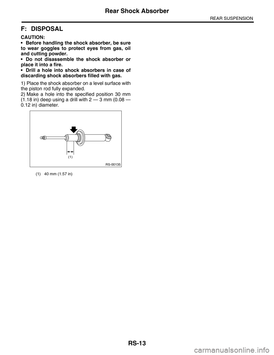
1) Place the shock absorber on a level surface with
the piston rod fully expanded.
2) Make a hole into the specified position 30 mm
(1.18 in) deep using a drill with 2 — 3 mm (0.08 —
0.12 in) diameter.
(1) 40 mm (1.57 in)
RS-00135
(1)
Page 950 of 2453

RS-17
General Diagnostic Table
REAR SUSPENSION
10.General Diagnostic Table
A: INSPECTION
1. IMPROPER VEHICLE POSTURE OR IMPROPER WHEEL ARCH HEIGHT
2. POOR RIDE COMFORT
1) Large rebound shock
2) Rocking of the vehicle continues too long after running over bump and hump.
3) Excessive shock in bumping
3. NOISE
Po ss ibl e c a us e C o r r e ct ive ac ti o n
(1) Permanent distortion or damaged coil spring Replace.
(2) Rough operation of damper strut or shock absorber Replace.
(3) Improper installation of strut or shock absorber Replace with proper parts.
(4) Installation of the wrong coil spring Replace with proper parts.
Po ss ibl e ca us e C or r e ct i ve a ct io n
(1) Damaged coil spring Replace.
(2) Overinflation of tires Adjust.
(3) Improper wheel arch height Adjust or replace the coil springs with new ones.
(4) Fault in operation of damper strut or shock absorber Replace.
(5) Damage or deformation of strut mount or shock absorber mount Replace.
(6) Unsuitable length (maximum or minimum) of damper strut or shock
absorber
Replace with appropriate parts.
(7) Deformation or loss of bushing Replace.
(8) Deformation or damage of helper in strut assembly or shock absorber Replace.
(9) Oil leakage from the damper strut or shock absorber Replace.
Po ss ibl e c a us e C o r r e ct ive ac ti o n
(1) Wear or damage of damper strut or shock absorber component parts Replace.
(2) Loosening of the suspension link installing bolt Tighten to the specified torque.
(3) Deformation or loss of bushing Replace.
(4) Unsuitable length (maximum or minimum) of damper strut or shock
absorber
Replace with appropriate parts.
(5) Damaged coil spring Replace.
(6) Wear or damage of the ball joint Replace.
(7) Deformation of the stabilizer clamp Replace.
Page 952 of 2453

TPM(diag)-2
Basic Diagnostic Procedure
TIRE PRESSURE MONITORING SYSTEM (DIAGNOSTICS)
1. Basic Diagnostic Procedure
A: PROCEDURE
CAUTION:
Remove foreign matter (dust, water, oil etc.) from the tire pressure monitoring control module con-
nector when removing or installing.
NOTE:
To check harness for broken wires or short circuits, shake trouble spot or connector.
Step Check Yes No
1CHECK PRE-INSPECTION.
1) Check with the user regarding when the
warning light lit or started blinking.
2) Before performing diagnostics, check the
components which might mal-affect tire pres-
sure monitor system.
Is the component that might
affect the tire pressure monitor
system normal?
Go to step 2.Repair or replace
each component.
2CHECK DIAGNOSTIC TROUBLE CODE
(DTC).
1) Turn the ignition switch to OFF.
2) Connect the Subaru Select Monitor to data
link connector.
3) Turn the ignition switch to ON and Subaru
Select Monitor to ON.
NOTE:If the communication function of the Subaru Se-
lect Monitor cannot be executed normally,
check the communication circuit.
TIALIZING IMPOSSIBLE, INSPECTION, Sub-
aru Select Monitor.>
4) Read the DTC.
(DTC).>
Is DTC displayed? Go to step 4.Go to step 3.
3PERFORM GENERAL DIAGNOSTICS.
1) Inspect using “General Diagnostic Table”.
2) Perform the clear memory mode.
Subaru Select Monitor.>
3) Perform the inspection mode.
4) Read the DTC.
OPERATION, Subaru Select Monitor.>
Check the DTC is not displayed.
Does the tire pressure warn-
ing light illuminates for about 2
seconds and then foes off after
turning on the ignition switch,
and then go out?
Finish the diagno-
sis.
Check using
“Diagnostic Proce-
dure for TPM”
WITHOUT DTC,
INSPECTION,
Subaru Select
Monitor.>
4PERFORM DIAGNOSIS.
1) Refer to “List of Diagnostic Trouble Code
(DTC).”
2) Correct the cause of trouble.
3) Perform the clear memory mode.
Subaru Select Monitor.>
4) Perform the drive test.
Drive the vehicle at a speed more than 40 km/h
(25 MPH) for at least 10 minutes.
5) Read the DTC.
OPERATION, Subaru Select Monitor.>
Is DTC displayed? Repeat steps 1 to
4 until DTC is not
shown.
Finish the diagno-
sis.
Page 990 of 2453

TC-5
Oil Seal
TRANSFER CASE
4. Oil Seal
A: NOTE
For inspection, refer to the 5AT section.
Page 1086 of 2453

VDC-5
General Description
VEHICLE DYNAMICS CONTROL (VDC)
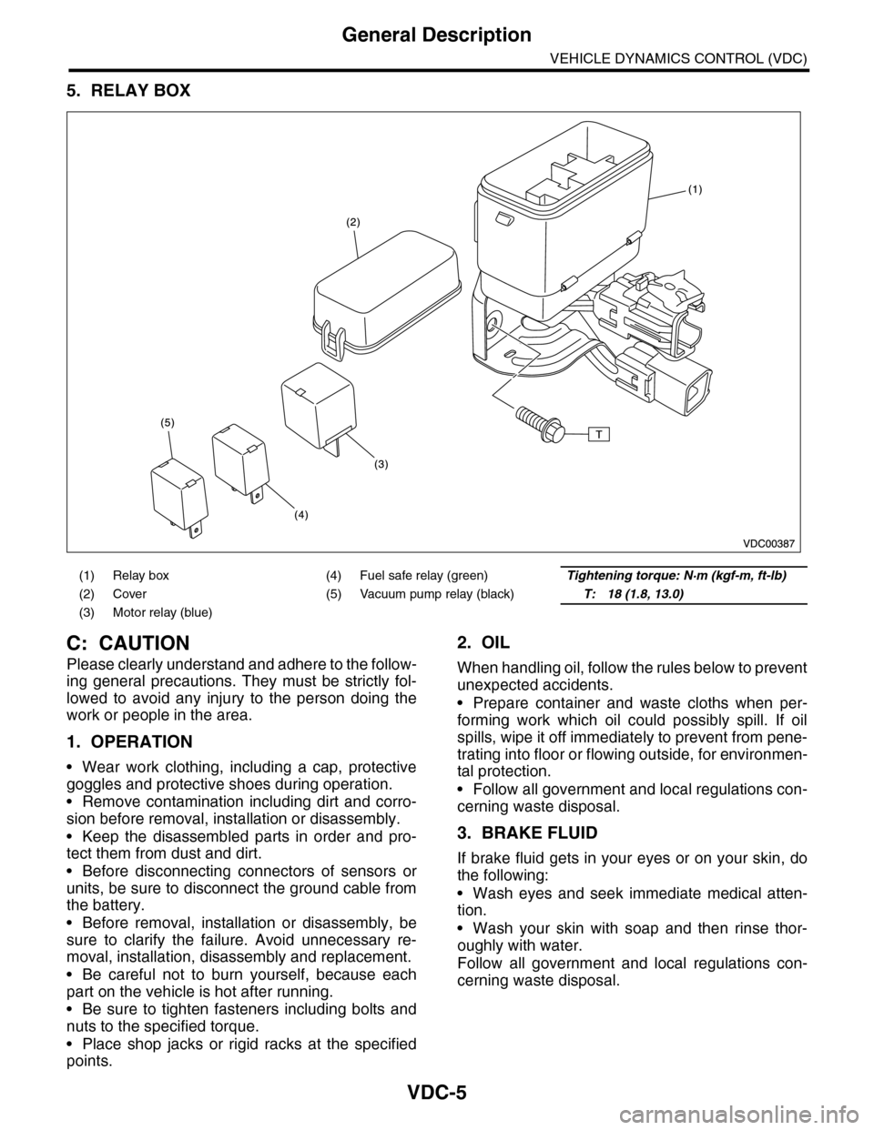
5. RELAY BOX
C: CAUTION
Please clearly understand and adhere to the follow-
ing general precautions. They must be strictly fol-
lowed to avoid any injury to the person doing the
work or people in the area.
1. OPERATION
•Wear work clothing, including a cap, protective
goggles and protective shoes during operation.
•Remove contamination including dirt and corro-
sion before removal, installation or disassembly.
•Keep the disassembled parts in order and pro-
tect them from dust and dirt.
•Before disconnecting connectors of sensors or
units, be sure to disconnect the ground cable from
the battery.
•Before removal, installation or disassembly, be
sure to clarify the failure. Avoid unnecessary re-
moval, installation, disassembly and replacement.
•Be careful not to burn yourself, because each
part on the vehicle is hot after running.
•Be sure to tighten fasteners including bolts and
nuts to the specified torque.
•Place shop jacks or rigid racks at the specified
points.
2. OIL
When handling oil, follow the rules below to prevent
unexpected accidents.
•Prepare container and waste cloths when per-
forming work which oil could possibly spill. If oil
spills, wipe it off immediately to prevent from pene-
trating into floor or flowing outside, for environmen-
tal protection.
•Follow all government and local regulations con-
cerning waste disposal.
3. BRAKE FLUID
If brake fluid gets in your eyes or on your skin, do
the following:
•Wash eyes and seek immediate medical atten-
tion.
•Wash your skin with soap and then rinse thor-
oughly with water.
Follow all government and local regulations con-
cerning waste disposal.
(1) Relay box (4) Fuel safe relay (green)Tightening torque: N·m (kgf-m, ft-lb)
(2) Cover (5) Vacuum pump relay (black)T: 18 (1.8, 13.0)
(3) Motor relay (blue)