2009 SUBARU TRIBECA Oil spec
[x] Cancel search: Oil specPage 828 of 2453

DS-11
Propeller Shaft
DRIVE SHAFT SYSTEM
13) Install an extension cap to the transmission.
NOTE:
If extension cap is not available, place vinyl bag
over opening and fasten with string to prevent gear
oil or ATF from leaking.
B: INSTALLATION
1) Insert the sleeve yoke into the transmission and
attach center bearing to body.
Tightening torque:
52 N·m (5.3 kgf-m, 38.3 ft-lb)
2) Align the matching marks and connect the flange
yoke and rear differential.
Tightening torque:
31 N·m (3.2 kgf-m, 23.1 ft-lb)
3) Install the heat shield cover.
4) Install the center exhaust pipe.
5) Install the rear exhaust pipe and muffler.
6) Lower the vehicle.
7) Connect the ground cable to the battery.
C: INSPECTION
NOTE:
Do not disassemble propeller shaft. Check the fol-
lowing and replace if necessary.
•Tube surface for dents of cracks
•Splines for deformation or abnormal wear
•Unsmooth joint operation or abnormal noise
•Center bearing for free play, noise or non-
smooth operation.
•Oil seals for abnormal wear or damage
•Damaged center bearing
Check the following points with propeller shaft in-
stalled in vehicle.
1. JOINTS AND CONNECTIONS
1) Remove the center exhaust pipe.
2) Remove the heat shield cover.
3) Check for any looseness of the yoke flange
mounting bolts which connect to the rear differen-
tial and center bearing bracket mounting bolts.
2. SPLINES AND BEARING
1) Remove the center exhaust pipe.
2) Remove the rear exhaust pipe and muffler.
3) Remove the heat shield cover.
4) Turn the propeller shaft by hand to see if abnor-
mal free play exists at splines. Also move yokes to
see if abnormal free play exists at spiders and
bearings.
(A) Extension cap
(A) Alignment mark
DS-00031
(A)
DS-00141
DS-00028
(A)
DS-00035
Page 841 of 2453

DS-24
Front Drive Shaft
DRIVE SHAFT SYSTEM
7. Front Drive Shaft
A: REMOVAL
1) Disconnect the ground cable from the battery.
2) Lift-up the vehicle, and remove the front wheels.
3) Lift the crimped section of axle nut.
4) Remove the axle nut using a socket wrench
while depressing the brake pedal.
CAUTION:
Remove the wheel before loosening the axle
nut. Failure to follow this rule may damage the
wheel bearings.
5) Remove the stabilizer link from front arm.
6) Disconnect the front arm ball joint from the front
housing.
7) Remove the front drive shaft assembly. If it is
hard to remove, use ST1 and ST2.
ST1 926470000 AXLE SHAFT PULLER
ST2 28099PA110 AXLE SHAFT PULLER
PLATE
8) Using a bar, remove the front drive shaft from
transmission.
CAUTION:
Be careful not to allow the bar to damage holder
area.
B: INSTALLATION
1) Using the ST, replace the differential side retain-
er oil seal with a new seal.
ST 18675AA000 DIFFERENTIAL SIDE OIL
SEAL INSTALLER
NOTE:
After pulling out the drive shaft, be sure to replace
with a new oil seal.
2) Insert the EBJ into hub splines.
3) Draw the drive shaft into specified position.
CAUTION:
Do not hammer drive shaft when installing it.
4) Tighten the axle nut temporarily.
5) Using the ST, install the front drive shaft to trans-
mission.
ST 28399SA010 OIL SEAL PROTECTOR
6) Connect the front arm ball joint to the front hous-
ing.
Tightening torque:
50 N·m (5.1 kgf-m, 36.9 ft-lb)
7) Install the stabilizer link.
Tightening torque:
60 N·m (6.1 kgf-m, 44.3 ft-lb)
CAUTION:
Be sure to use a new self-locking nut.
DS-00038
FS-00106
DS-00145
ST2
ST1
MT-00103
ST
AT-00110ST
Page 845 of 2453

DS-28
Rear Drive Shaft
DRIVE SHAFT SYSTEM
8. Rear Drive Shaft
A: REMOVAL
1) Disconnect the ground cable from the battery.
2) Lift-up the vehicle, and then remove the rear
wheels.
3) Lift the crimped section of axle nut.
4) While applying the parking brake, remove the
axle nut using a socket wrench.
CAUTION:
Remove the wheel before loosening the axle
nut. Failure to follow this rule may damage the
wheel bearings.
5) Remove the rear differential assembly.
VA-type
6) Remove the axle nut and rear drive shaft. If it is
hard to remove, use ST1 and ST2.
ST1 926470000 AXLE SHAFT PULLER
ST2 28099PA110 AXLE SHAFT PULLER
PLATE
CAUTION:
•Do not hammer drive shaft when removing.
•Do not damage the oil seal and magnetic en-
coder.
B: INSTALLATION
1) Insert the EBJ into hub splines.
CAUTION:
•Be careful not to damage the magnetic en-
coder.
•Do not get closer the tool which charged
magnetism to magnetic encoder.
2) Draw the rear drive shaft into specified position.
CAUTION:
Do not hammer drive shaft when installing it.
3) Tighten the axle nut temporarily.
4) Install the rear differential assembly.
VA-type
5) While applying the parking brake and depress-
ing the brake pedal, tighten a new axle nut (olive
color) to the specified torque and lock it securely.
Tightening torque:
240 N·m (24.5 kgf-m, 177 ft-lb)
CAUTION:
•Install the wheel after installation of axle nut.
Failure to follow this rule may damage the
wheel bearing.
•Be sure to tighten the axle nut to specified
torque. Do not overtighten it as this may dam-
age the wheel bearing.
6) Lock the axle nut securely.
DS-00038
DS-00122
ST2ST1
(1) Magnetic encoder
(2) Rear hub unit bearing
DS-00251
(2)
(1)
DS-00048
Page 852 of 2453

FS-4
General Description
FRONT SUSPENSION
C: CAUTION
Please understand and adhere to the following general precautions. They must be strictly followed to avoid
any injury to the person performing the work or persons in the area.
1. OPERATION
•Wear work clothing, including a cap, protective goggles and protective shoes during operation.
•Before removal, installation or disassembly, be sure to clarify the failure. Avoid unnecessary removal, in-
stallation, disassembly and replacement.
•Use SUBARU genuine grease etc. or equivalent. Do not mix grease etc. with that of another grade or from
other manufacturers.
•Before securing a part on a vise, place cushioning material such as wood blocks, aluminum plate, or cloth
between the part and the vise.
•Be sure to tighten fasteners including bolts and nuts to the specified torque.
•Place shop jacks or rigid racks at the specified points.
2. OIL
When handling oil, follow the rules below to prevent unexpected accidents.
•Prepare container and waste cloths when performing work which oil could possibly spill. If oil spills, wipe
it off immediately to prevent from penetrating into floor or flowing outside, for environmental protection.
•Follow all government and local regulations concerning waste disposal.
D: PREPARATION TOOL
1. SPECIAL TOOL
ILLUSTRATION TOOL NUMBER DESCRIPTION REMARKS
927680000 INSTALLER &
REMOVER SET
Used for replacing front arm front bushing.
20299AG000 REMOVER Used for replacing front arm rear bushing.
Used with BASE (20999AG010).
ST-927680000
ST20299AG000
Page 869 of 2453

FS-21
Front Strut
FRONT SUSPENSION
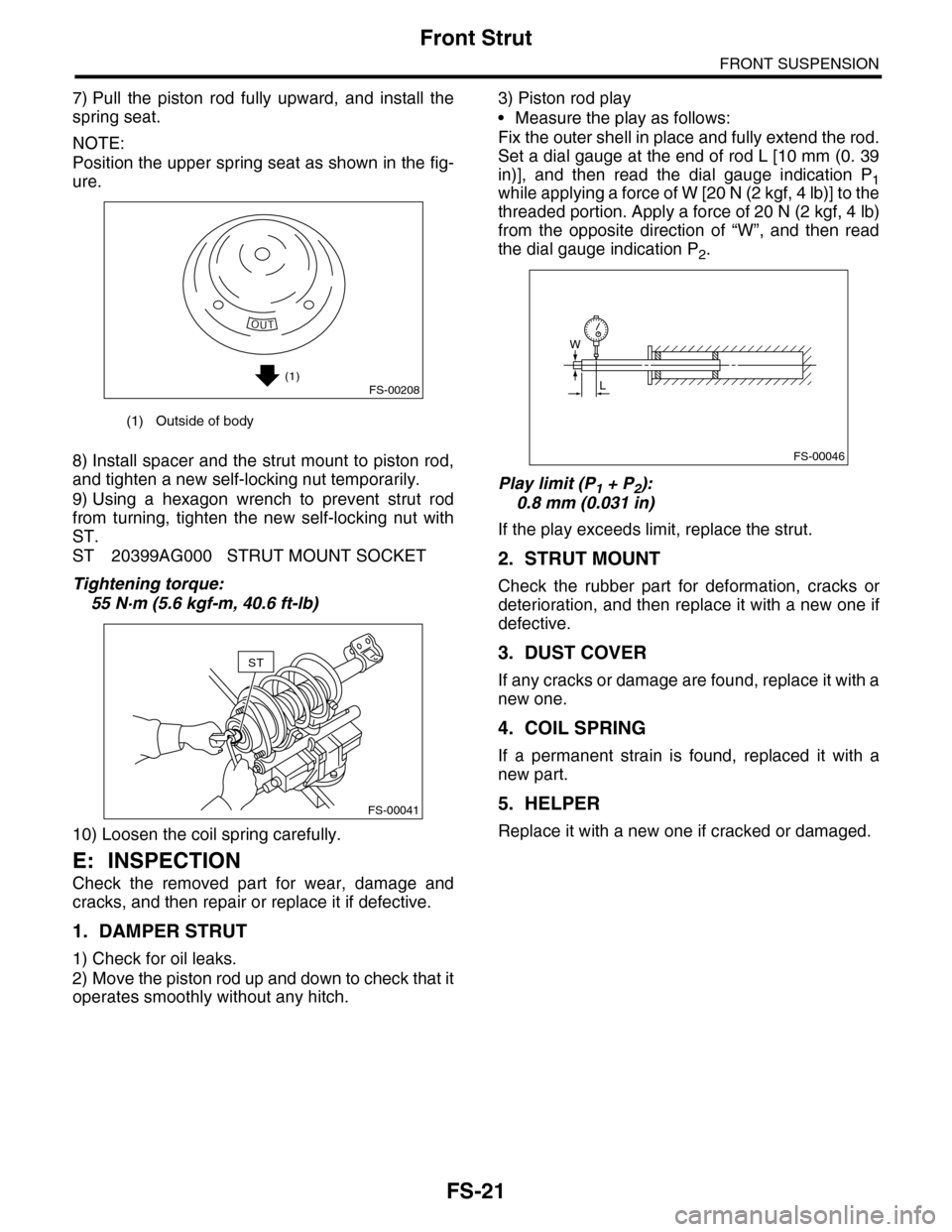
7) Pull the piston rod fully upward, and install the
spring seat.
NOTE:
Position the upper spring seat as shown in the fig-
ure.
8) Install spacer and the strut mount to piston rod,
and tighten a new self-locking nut temporarily.
9) Using a hexagon wrench to prevent strut rod
from turning, tighten the new self-locking nut with
ST.
ST 20399AG000 STRUT MOUNT SOCKET
Tightening torque:
55 N·m (5.6 kgf-m, 40.6 ft-lb)
10) Loosen the coil spring carefully.
E: INSPECTION
Check the removed part for wear, damage and
cracks, and then repair or replace it if defective.
1. DAMPER STRUT
1) Check for oil leaks.
2) Move the piston rod up and down to check that it
operates smoothly without any hitch.
3) Piston rod play
•Measure the play as follows:
Fix the outer shell in place and fully extend the rod.
Set a dial gauge at the end of rod L [10 mm (0. 39
in)], and then read the dial gauge indication P1while applying a force of W [20 N (2 kgf, 4 lb)] to the
threaded portion. Apply a force of 20 N (2 kgf, 4 lb)
from the opposite direction of “W”, and then read
the dial gauge indication P2.
Play limit (P1 + P2):
0.8 mm (0.031 in)
If the play exceeds limit, replace the strut.
2. STRUT MOUNT
Check the rubber part for deformation, cracks or
deterioration, and then replace it with a new one if
defective.
3. DUST COVER
If any cracks or damage are found, replace it with a
new one.
4. COIL SPRING
If a permanent strain is found, replaced it with a
new part.
5. HELPER
Replace it with a new one if cracked or damaged.
(1) Outside of body
(1)FS-00208
FS-00041
ST
FS-00046
W
L
Page 872 of 2453

FS-24
General Diagnostic Table
FRONT SUSPENSION
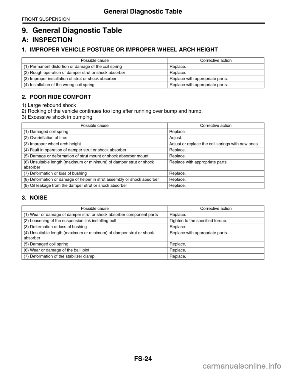
9. General Diagnostic Table
A: INSPECTION
1. IMPROPER VEHICLE POSTURE OR IMPROPER WHEEL ARCH HEIGHT
2. POOR RIDE COMFORT
1) Large rebound shock
2) Rocking of the vehicle continues too long after running over bump and hump.
3) Excessive shock in bumping
3. NOISE
Po ss ibl e c a us e C o r r e ct ive ac ti o n
(1) Permanent distortion or damage of the coil spring Replace.
(2) Rough operation of damper strut or shock absorber Replace.
(3) Improper installation of strut or shock absorber Replace with appropriate parts.
(4) Installation of the wrong coil spring Replace with appropriate parts.
Po ss ibl e ca us e C or r e ct i ve a ct io n
(1) Damaged coil spring Replace.
(2) Overinflation of tires Adjust.
(3) Improper wheel arch height Adjust or replace the coil springs with new ones.
(4) Fault in operation of damper strut or shock absorber Replace.
(5) Damage or deformation of strut mount or shock absorber mount Replace.
(6) Unsuitable length (maximum or minimum) of damper strut or shock
absorber
Replace with appropriate parts.
(7) Deformation or loss of bushing Replace.
(8) Deformation or damage of helper in strut assembly or shock absorber Replace.
(9) Oil leakage from the damper strut or shock absorber Replace.
Po ss ibl e c a us e C o r r e ct ive ac ti o n
(1) Wear or damage of damper strut or shock absorber component parts Replace.
(2) Loosening of the suspension link installing bolt Tighten to the specified torque.
(3) Deformation or loss of bushing Replace.
(4) Unsuitable length (maximum or minimum) of damper strut or shock
absorber
Replace with appropriate parts.
(5) Damaged coil spring Replace.
(6) Wear or damage of the ball joint Replace.
(7) Deformation of the stabilizer clamp Replace.
Page 879 of 2453

PB-8
Parking Brake Assembly (Rear Disc Brake)
PARKING BRAKE
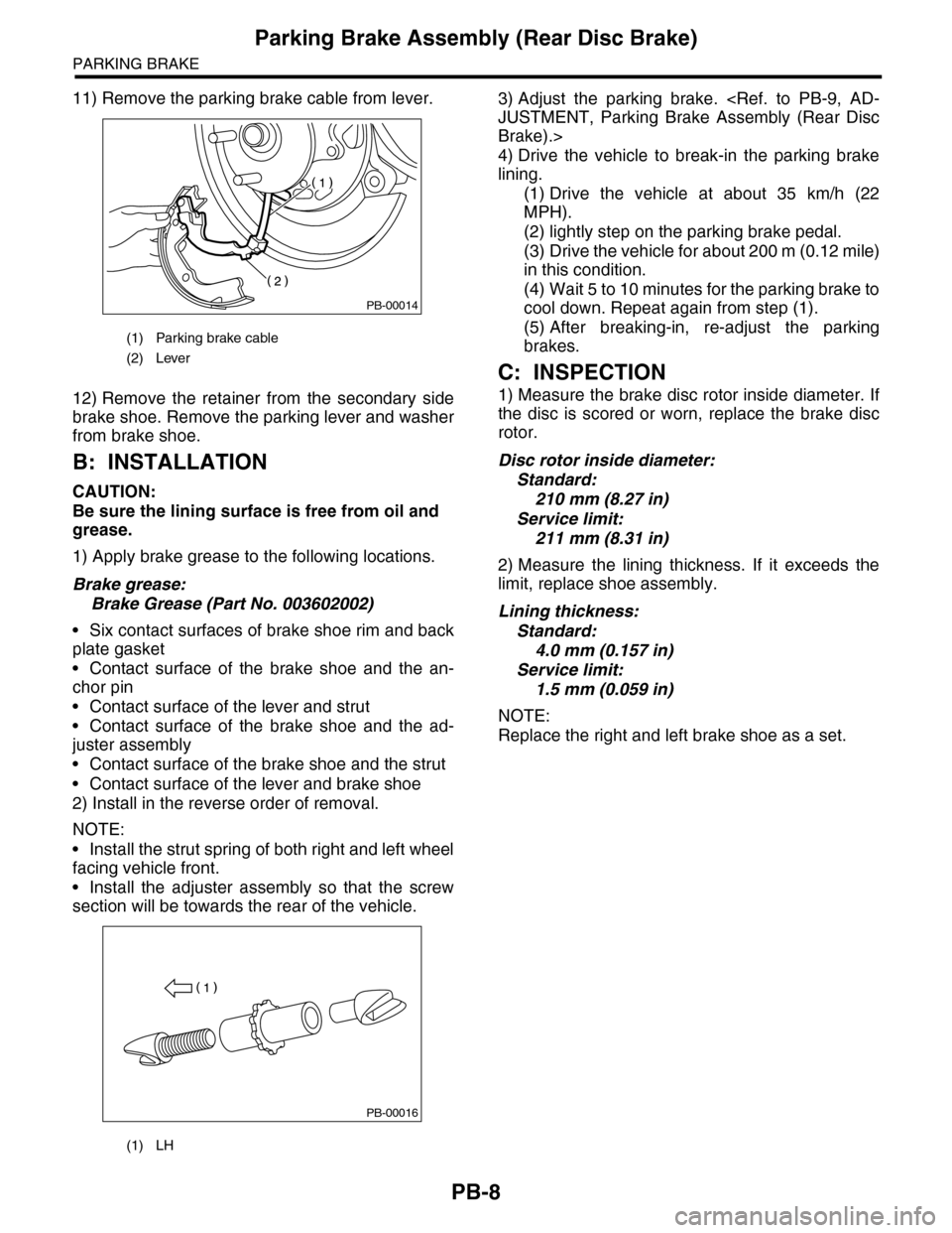
11) Remove the parking brake cable from lever.
12) Remove the retainer from the secondary side
brake shoe. Remove the parking lever and washer
from brake shoe.
B: INSTALLATION
CAUTION:
Be sure the lining surface is free from oil and
grease.
1) Apply brake grease to the following locations.
Brake grease:
Brake Grease (Part No. 003602002)
•Six contact surfaces of brake shoe rim and back
plate gasket
•Contact surface of the brake shoe and the an-
chor pin
•Contact surface of the lever and strut
•Contact surface of the brake shoe and the ad-
juster assembly
•Contact surface of the brake shoe and the strut
•Contact surface of the lever and brake shoe
2) Install in the reverse order of removal.
NOTE:
•Install the strut spring of both right and left wheel
facing vehicle front.
•Install the adjuster assembly so that the screw
section will be towards the rear of the vehicle.
3) Adjust the parking brake.
Brake).>
4) Drive the vehicle to break-in the parking brake
lining.
(1) Drive the vehicle at about 35 km/h (22
MPH).
(2) lightly step on the parking brake pedal.
(3) Drive the vehicle for about 200 m (0.12 mile)
in this condition.
(4) Wait 5 to 10 minutes for the parking brake to
cool down. Repeat again from step (1).
(5) After breaking-in, re-adjust the parking
brakes.
C: INSPECTION
1) Measure the brake disc rotor inside diameter. If
the disc is scored or worn, replace the brake disc
rotor.
Disc rotor inside diameter:
Standard:
210 mm (8.27 in)
Service limit:
211 mm (8.31 in)
2) Measure the lining thickness. If it exceeds the
limit, replace shoe assembly.
Lining thickness:
Standard:
4.0 mm (0.157 in)
Service limit:
1.5 mm (0.059 in)
NOTE:
Replace the right and left brake shoe as a set.
(1) Parking brake cable
(2) Lever
(1) LH
PB-00014
PB-00016
Page 882 of 2453

PS-2
General Description
POWER ASSISTED SYSTEM (POWER STEERING)
1. General Description
A: SPECIFICATION
Whole system
Minimum turning radius m (ft) 5.7 (18.7)
Steering angleInner wheel 37.0°±1.5°
Outer wheel 32.0°±1.5
Steering wheel diameter mm (in) 375 (14.76)
Lock to lock turn 3.44
Gearbox
Ty p e R a c k a n d P i n i o n , I n t e g r a l
Backlash 0 (Automatic adjusting)
Va l ve ( Po w e r s t e e r i n g s y s t e m ) R o t a r y va l ve
Pump
(Power steering
system)
Ty p e Va n e p u m p
Oil tank Installed on body
Specific outputcm3 (cu in)/rev.9.6 (0.586)
Relief pressurekPa (kg/cm2, psi)8,800 — 9,400 (90 — 96, 1,276 — 1,363)
Hydraulic fluid control Engine RPM sensitive
Hydraulic fluid2(US qt, Imp qt)1,000 rpm: 7.0 (7.4, 6.2)
3,000 rpm: 6.0 (6.3, 5.3)
RPM Range rpm 500 — 8,600
Direction of rotation Clockwise
Hydraulic oil
(Power steering
system)
Description ATF DEXRON III or equivalent
Capacity
2(US qt, Imp qt)
Oil tank 0.2 (0.2, 0.2)
Whole system 0.9 (1.0, 0.8)
Steering wheel Free play mm (in) 17 (0.67)
Steering shaftClearance between the steering wheel and
column covermm (in) 3.0 (0.12)
Steering gear-
box
(Power steering
system)
Sliding resistance N (kgf, lb)
400 (41, 90) or less
Difference between right and left sliding resistance:
Less than 20%
Rack shaft play in
the radial direction
Right–turn steering mm (in) 0.19 (0.0075) or less
Left–turn steering mm (in)Horizontal movement: 0.6 (0.024) or less
Ve r t i c a l m o v e m e n t : 0 . 4 ( 0 . 0 1 6 ) o r l e s s
Input shaft playIn radial direction mm (in) 0.18 (0.0071) or less
In axial direction mm (in) 0.27 (0.0106) or less
Rotation resistance N (kgf, lb)
Maximum allowable value: 10.5 (1.07, 2.36) or less
Difference between right and left sliding resistance:
Less than 20%
Oil Pump
(Power steering
system)
Pulley shaftRadial play mm (in) 0.2 (0.008) or less
Axial play mm (in) 0.6 (0.024) or less
PulleyDitch deflection mm (in) 1.0 (0.039) or less
Rotation resistance N (kgf, lb) 9.22 (0.94, 2.07) or less
Regular pressure (Unloaded)kPa (kg/cm2, psi)981 (10, 142) or less
Steering wheel
effort (Power
steering sys-
tem)
At standstill with engine idling on paved road N (kgf, lb) 29.4 (3.0, 6.6) or less
At standstill with engine stalled on paved
roadN (kgf, lb) 294.2 (30, 66.2) or less