2009 SUBARU TRIBECA Oil spec
[x] Cancel search: Oil specPage 320 of 2453

GW-25
Rear Window Defogger
GLASS/WINDOWS/MIRRORS
17.Rear Window Defogger
A: INSPECTION
1. CHECK WITH SUBARU SELECT MONITOR
CAUTION:
Check that the rear window defogger timer is in initial setting or customize setting before performing
inspection.
2. HEAT WIRE INSPECTION
CAUTION:
Use a dry and soft cloth when wiping dirt off the
glass. Move the cloth along the heat wire to
avoid damaging it.
1) Turn the ignition switch to ON.
2) Turn the defogger switch to ON.
3) Wrap the tips of tester probe with aluminum foil
to avoid damage to heat wire.
4) Measure the voltage at heat wire center with DC
voltmeter.
Standard voltage:
Approx. 6 V
NOTE:
•If the measured value is 12 volts, heat wire is
open between heat wire center and positive (+) ter-
minal of tester probe.
•If it is 0 V, the circuit is open between heat wire
center and ground.
Step Check Yes No
1CHECK INPUT SIGNAL TO THE BODY INTE-
GRATED UNIT.
Check the input signal when the rear window
defogger switch is operated using Subaru
Select Monitor.
1) Connect the Subaru Select Monitor to data
link connector.
2) Turn the ignition switch to ON.
3) Select {Integ. unit} from the «main menu».
4) Select the {Current Data Display & Save}.
5) Check the input signal when the rear win-
dow defogger switch is set to ON.
After rear defogger switch is
set to ON, does it turn to OFF
in 15 minutes? Or does it
repeat 15 minutes operation
and 2 minutes stop?
END. Replace the body
integrated unit.
Integrated Unit.>
(1) Tester probe
(2) Aluminum foil
(3) Heat wire
(4) Press
GW-00076
(2)
(3)
(4)
(1)
(1) Center of heat wire
Vo l t a g e C r i t e r i a
Approx. 6 V Normal
Approx. 12 V or 0 V Open
GW-00077
(1)
Page 341 of 2453

AC-15
General Description
HVAC SYSTEM (HEATER, VENTILATOR AND A/C)
5. O-RING CONNECTIONS
•Always use a new O-ring.
•In order to keep the O-rings free of lint which can
cause a refrigerant gas leak, perform operations
without gloves and cloth.
•Apply compressor oil to O-rings to avoid sticking,
before installation.
•Use a torque wrench to tighten the O-ring fittings.
Over-tightening will cause damage to the O-ring
and cause tube end distortion.
•If the work is interrupted before completing pipe
connections, recap the tubes, components and fit-
tings with a plug or tape to prevent foreign matter
from entering.
•Visually check the surfaces and mating surfaces
of O-rings, threads and connecting points. If a fail-
ure is found, replace the applicable parts.
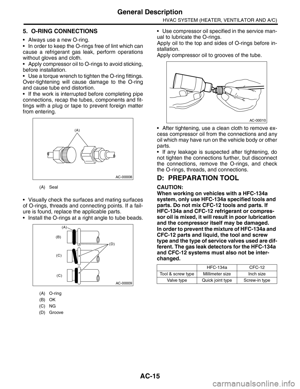
•Install the O-rings at a right angle to tube beads.
•Use compressor oil specified in the service man-
ual to lubricate the O-rings.
Apply oil to the top and sides of O-rings before in-
stallation.
Apply compressor oil to grooves of the tube.
•After tightening, use a clean cloth to remove ex-
cess compressor oil from the connections and any
oil which may have run on the vehicle body or other
parts.
•If any leakage is suspected after tightening, do
not tighten the connections further, but disconnect
the connections, remove the O-rings, and check
the O-rings, threads, and connections.
D: PREPARATION TOOL
CAUTION:
When working on vehicles with a HFC-134a
system, only use HFC-134a specified tools and
parts. Do not mix CFC-12 tools and parts. If
HFC-134a and CFC-12 refrigerant or compres-
sor oil is mixed, it will result in poor lubrication
and the compressor itself may be damaged.
In order to prevent the mixture of HFC-134a and
CFC-12 parts and liquid, the tool and screw
type and the type of service valves used are dif-
ferent. The gas leak detectors for the HFC-134a
and CFC-12 systems must also not be inter-
changed.
(A) Seal
(A) O-ring
(B) OK
(C) NG
(D) Groove
(A)
AC-00008
AC-00009
(D)
(B)
(C)
(C)
(A)
HFC-134aCFC-12
To o l & s c r e w t y p e M i l l i m e t e r s i z e I n c h s i z e
Va l ve t y p e Q u i ck j o i n t t y p e S c r ew - i n t y p e
AC-00010
Page 342 of 2453

AC-16
General Description
HVAC SYSTEM (HEATER, VENTILATOR AND A/C)
1. SPECIAL TOOL
NOTE:
Read the instruction manual for the connector remover before using.
2. GENERAL TOOL
ILLUSTRATION TOOL NUMBER DESCRIPTION REMARKS
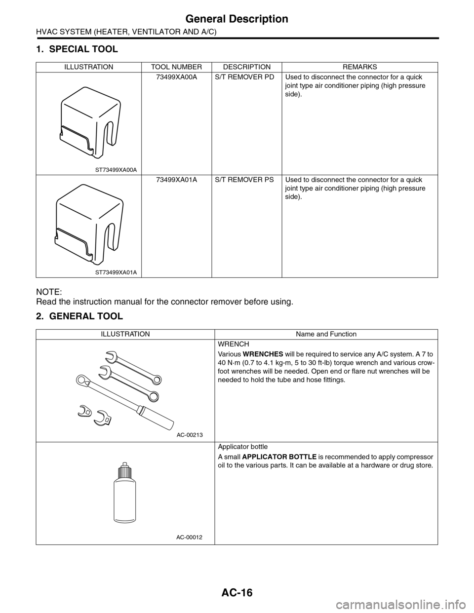
73499XA00A S/T REMOVER PD Used to disconnect the connector for a quick
joint type air conditioner piping (high pressure
side).
73499XA01A S/T REMOVER PS Used to disconnect the connector for a quick
joint type air conditioner piping (high pressure
side).
ILLUSTRATION Name and Function
WRENCH
Va r i o u s WRENCHES will be required to service any A/C system. A 7 to
40 N·m (0.7 to 4.1 kg-m, 5 to 30 ft-lb) torque wrench and various crow-
foot wrenches will be needed. Open end or flare nut wrenches will be
needed to hold the tube and hose fittings.
Applicator bottle
A small APPLICATOR BOTTLE i s r e c om me nd e d to a p pl y co mp r e ss or
oil to the various parts. It can be available at a hardware or drug store.
ST73499XA00A
ST73499XA01A
AC-00213
AC-00012
Page 346 of 2453

AC-20
Refrigerant Recovery Procedure
HVAC SYSTEM (HEATER, VENTILATOR AND A/C)
3. Refrigerant Recovery Proce-
dure
A: PROCEDURE
CAUTION:
•During operation, be sure to wear protective
goggles and protective gloves.
•Connect the refrigerant recovery system with
the manifold gauge set to discharge the refrig-
erant from the A/C system and recycle the gas.
•When recycling the discharged refrigerant,
keep service cans on hand. Because the recov-
ery rate with the recovery system is approx.
90%, service cans are necessary to charge the
refrigerant.
•Follow the detailed operation procedure de-
scribed in the operation manual attached to the
refrigerant recovery system.
1) Perform the compressor oil return operation.
2) Stop the engine.
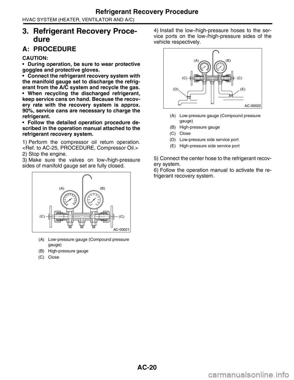
3) Make sure the valves on low-/high-pressure
sides of manifold gauge set are fully closed.
4) Install the low-/high-pressure hoses to the ser-
vice ports on the low-/high-pressure sides of the
vehicle respectively.
5) Connect the center hose to the refrigerant recov-
ery system.
6) Follow the operation manual to activate the re-
frigerant recovery system.
(A) Low-pressure gauge (Compound pressure
gauge)
(B) High-pressure gauge
(C) Close
AC-00021
(A) (B)
(C)(C)
(A) Low-pressure gauge (Compound pressure
gauge)
(B) High-pressure gauge
(C) Close
(D) Low-pressure side service port
(E) High-pressure side service port
AC-00022
(A) (B)
(C)(C)
(E)(D)
Page 350 of 2453

AC-24
Refrigerant Leak Check
HVAC SYSTEM (HEATER, VENTILATOR AND A/C)
5. Refrigerant Leak Check
A: INSPECTION
1) At engine speed below 1500rpm, operate the A/
C system for approx. 10 minutes, and confirm that
the high-side pressure shows at least 690 kPa
(7.03 kg/cm2, 100 psi). Then stop the engine to
start the leak test.
2) Starting from the connection between high-pres-
sure pipe and evaporator, check the system for
leaks along the high-pressure side through the
compressor. The following items must be checked
thoroughly.
3) Check the joint and seam between pressure
switch (dual switch) and high-pressure pipe.
4) Check the connections between condenser and
pipes, and welded joints on the condenser.
The leak tester may detect the oil on the condenser
fins as a leak.
5) Check the joint between compressor and hoses.
6) Check the machined area of the compressor and
other joints on the compressor.
7) Check the compressor shaft seal at the area
near the center of compressor clutch pulley.
Some shaft seals show a slight amount of leakage,
about 3 g (0.1 oz) per year. This is not a problem.
8) Starting from the connection between low-pres-
sure pipe and evaporator, check the system for
leakage along the low-pressure side through the
compressor. The following items must be checked
thoroughly.
•Connection between 2 parts
•Connection between pipe and plate
•Connection between pipes
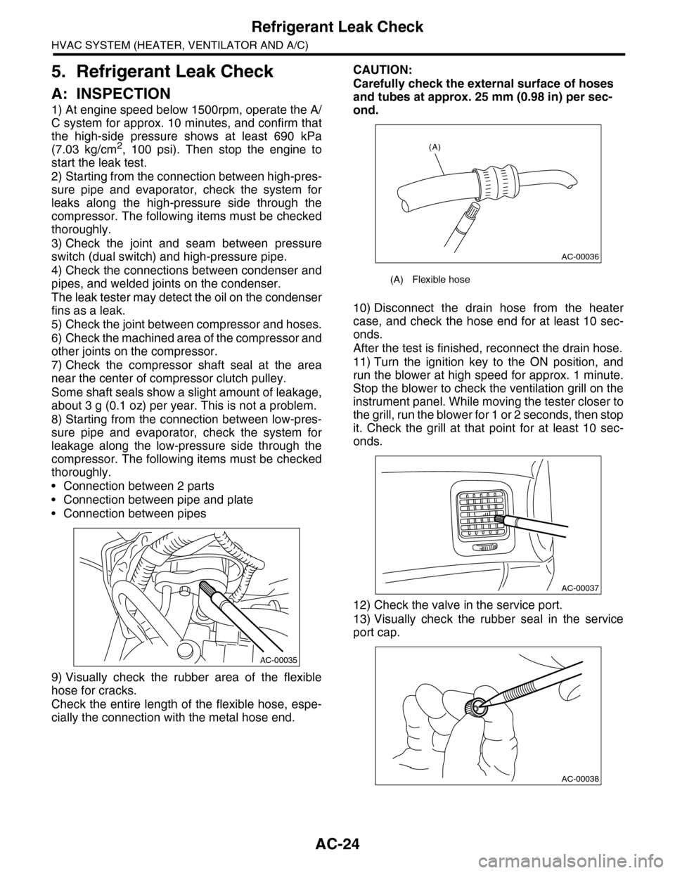
9) Visually check the rubber area of the flexible
hose for cracks.
Check the entire length of the flexible hose, espe-
cially the connection with the metal hose end.
CAUTION:
Carefully check the external surface of hoses
and tubes at approx. 25 mm (0.98 in) per sec-
ond.
10) Disconnect the drain hose from the heater
case, and check the hose end for at least 10 sec-
onds.
After the test is finished, reconnect the drain hose.
11) Turn the ignition key to the ON position, and
run the blower at high speed for approx. 1 minute.
Stop the blower to check the ventilation grill on the
instrument panel. While moving the tester closer to
the grill, run the blower for 1 or 2 seconds, then stop
it. Check the grill at that point for at least 10 sec-
onds.
12) Check the valve in the service port.
13) Visually check the rubber seal in the service
port cap.
AC-00035
(A) Flexible hose
AC-00036
(A)
AC-00037
AC-00038
Page 351 of 2453

AC-25
Compressor Oil
HVAC SYSTEM (HEATER, VENTILATOR AND A/C)
6. Compressor Oil
A: PROCEDURE
NOTE:
Before making repairs, perform the oil return oper-
ation to return the compressor oil in circulation with
the refrigerant to the compressor.
1) Increase the engine to 1,500 rpm.
2) Turn on the A/C switch.
3) Turn the temperature control switch to MAX
COOL.
4) Put in RECIRC position.
5) Turn the blower control switch to HI. (For models
with rear coolers, also turn the rear cooler fan
switch to HI)
6) Leave in this condition for 10 minutes.
B: REPLACEMENT
NOTE:
•If a component has been replaced, add an ap-
propriate amount of compressor oil (same as the
amount of remaining oil in removed component).
•When replacing the compressor, the new com-
pressor will already have the specified amount of
oil in it. Install the new compressor after removing
the same amount of oil that is remaining in the com-
pressor removed.
Page 359 of 2453

AC-33
Compressor
HVAC SYSTEM (HEATER, VENTILATOR AND A/C)
14.Compressor
A: INSPECTION
1. MAGNETIC CLUTCH CLEARANCE
Check the clearance of the entire circumference
around the drive plate and pulley.
Standard:
0.45±0.15 mm (0.0177±0.0059 in)
2. MAGNETIC CLUTCH OPERATION
1) Disconnect the compressor connector.
2) Connect the positive (+) lead from the battery to
the compressor connector terminal, and the nega-
tive (–) lead to the compressor body.
3) Check the magnet clutch engagement.
If there is a problem, replace the compressor.
B: REMOVAL
1) Perform the compressor oil return operation.
2) Turn the A/C switch to OFF and stop the engine.
3) Using the refrigerant recovery system, dis-
charge refrigerant.
4) Disconnect the ground cable from battery.
5) Remove the V-belts.
6) Remove the generator.
7) Remove the bolt and remove the low-pressure
hose and high-pressure hose.
8) Disconnect the compressor harness from the
body harness.
9) Remove the bolts and remove the compressor
bracket.
10) Remove the bolts, then remove the bracket
from the compressor.
C: INSTALLATION
1) Install in the reverse order of removal.
2) Replace the O-rings on low-/high-pressure hos-
es with new parts, then apply compressor oil.
3) After replacing the compressor, adjust the
amount of compressor oil.
4) Charge refrigerant.
Tightening torque:
Refer to “COMPONENT” of “General Descrip-
tion”.
AC-01287
AC-01381
AC-01289
AC-01290
Page 360 of 2453

AC-34
Condenser
HVAC SYSTEM (HEATER, VENTILATOR AND A/C)
15.Condenser
A: REMOVAL
1) Using the refrigerant recovery system, dis-
charge refrigerant.
2) Disconnect the ground cable from battery.
3) Remove the bumper upper cover.
4) Disconnect the pressure hose and pipe from the
condenser.
5) Remove the 4 bolts, lift the condenser and pull
out from the space between the radiator and
bumper.
CAUTION:
•Be careful not to damage the condenser fins.
If a damaged fin is found, repair it using a thin
screwdriver.
•If the condenser is replaced, add an appropri-
ate amount of compressor oil to the compres-
sor.
B: INSTALLATION
1) Install in the reverse order of removal.
CAUTION:
Replace the O-rings on hoses or pipes with new
parts, and then apply compressor oil.
2) Charge refrigerant.
Tightening torque:
Refer to “COMPONENT” of “General Descrip-
tion”.
tion.>
C: INSPECTION
1) Check to see that the condenser fins are not
clogged with debris or insects. Blow with com-
pressed air or flush fins with water as needed.
2) Inspect for oil leakage from the condenser. If a
failure is found, replace the condenser with a new
one.
AC-01292
AC-01291
AC-01293