Page 441 of 2453

IDI-2
General Description
INSTRUMENTATION/DRIVER INFO
1. General Description
A: SPECIFICATION
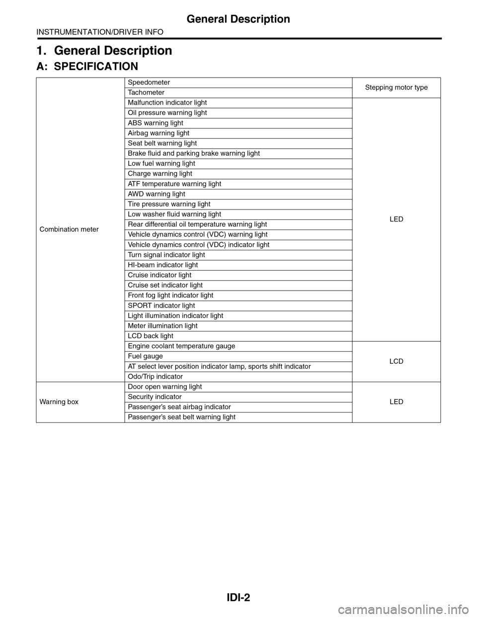
Combination meter
SpeedometerStepping motor typeTa c h o m e t e r
Malfunction indicator light
LED
Oil pressure warning light
ABS warning light
Airbag warning light
Seat belt warning light
Brake fluid and parking brake warning light
Low fuel warning light
Charge warning light
AT F t e m p e r a t u r e w a r n i n g l i g h t
AW D war n in g l i gh t
Tire pressure warning light
Low washer fluid warning light
Rear differential oil temperature warning light
Ve h i c l e d y n a m i c s c o n t r o l ( V D C ) w a r n i n g l i g h t
Ve h i c l e d y n a m i c s c o n t r o l ( V D C ) i n d i c a t o r l i g h t
Tu r n s i g n a l i n d i c a t o r l i g h t
HI-beam indicator light
Cruise indicator light
Cruise set indicator light
Fr o nt fog li g ht i nd i ca to r li g ht
SPORT indicator light
Light illumination indicator light
Meter illumination light
LCD back light
Engine coolant temperature gauge
LCDFuel gauge
AT s e l e c t l e v e r p o s i t i o n i n d i c a t o r l a m p , s p o r t s s h i f t i n d i c a t o r
Odo/Trip indicator
Wa r ni n g b ox
Door open warning light
LEDSecurity indicator
Passenger’s seat airbag indicator
Passenger’s seat belt war ning light
Page 458 of 2453

LAN(diag)-2
Basic Diagnostic Procedure
LAN SYSTEM (DIAGNOSTICS)
1. Basic Diagnostic Procedure
A: PROCEDURE
1. WITH SUBARU SELECT MONITOR
CAUTION:
•Subaru Select Monitor is required for reading DTC, performing diagnosis and reading current data.
•Remove foreign matter (dust, water, oil, etc.) from the body integrated unit connector during re-
moval and installation.
•For model with immobilizer, registration of immobilizer may be needed after the replacement of
controller etc. For detailed procedure, refer to the REGISTRATION MANUAL FOR IMMOBILIZER.
NOTE:
•To check harness for broken wires or short circuits, shake trouble spot or connector.
•Check List for Interview.
Step Check Yes No
1CHECK PRE-INSPECTION.
1) Ask the customer when and how the trou-
ble occurred using interview check list.
LAN(diag)-3, Check List for Interview.>
2) Check the display of communication error
display. (Combination meter, odo/trip meter)
Is the communication error dis-
played?
Go to step 3.Go to step 2.
2BASIC INSPECTION
Check the components which might affect
body control.
TION, General Description.>
Is the component that might
influence the body control
problem normal?
Go to step 3.Repair or replace
each component.
3CHECK INDICATION OF DTC.
1) Read DTC of all systems.
LAN(diag)-12, READ DIAGNOSTIC TROUBLE
CODE (DTC), OPERATION, Subaru Select
Monitor.>
NOTE:•The LAN system is for the overall vehicle, so
read the DTC of all systems.
•If the communication function of the Subaru
Select Monitor cannot be executed normally,
check the communication circuit.
LAN(diag)-32, COMMUNICATION FOR INI-
TIALIZING IMPOSSIBLE, Diagnostic Proce-
dure with Diagnostic Trouble Code (DTC).>
2) Record all DTC.
Is a DTC other than CAN com-
munication displayed in the
output code?
ECU: P0600 TCU: P1718 VDC
CU: C0047 or C0057, etc.
Refer to the DTC
related table.
to LAN(diag)-31,
FUNCTION
CHECK, DTC
TA B L E , L i s t o f
Diagnostic Trou-
ble Code (DTC).>
Go to step 5.
Go to step 4.
4PERFORM GENERAL DIAGNOSTICS.
Inspect using “General Diagnostics Table”.
Ta b l e . >
Is result of inspection OK? LAN system is nor-
mal.
Go to step 5.
5PERFORM DIAGNOSIS.
1) Correct the cause of trouble.
2) Perform the clear memory mode.
LAN(diag)-21, CLEAR MEMORY MODE,
OPERATION, Subaru Select Monitor.>
3) Read the DTC.
READ DIAGNOSTIC TROUBLE CODE (DTC),
OPERATION, Subaru Select Monitor.>
Is DTC displayed? Repeat step 5 until
DTC is not shown.
Finish the diagno-
sis.
Page 546 of 2453

LI-13
Headlight Bulb
LIGHTING SYSTEM
11.Headlight Bulb
A: REMOVAL
1. HIGH BEAM AND LOW BEAM
CAUTION:
•Because the halogen bulb operates at a high
temperature, dirt and oil on the bulb surface re-
duces the bulb's service life. Hold the flange
portion when replacing the bulb. Never touch
the glass portion.
•Do not leave the headlight without a bulb for
a long time. Dust, moisture, etc. entering the
headlight may affect its performance.
1) Disconnect the ground cable from battery.
2) Remove the air intake duct. (When removing the
headlight bulb RH)
3) Remove the battery. (When removing the head-
light bulb LH)
4) Disconnect the harness connector.
5) Remove the bulb assembly (A) then remove the
high beam. To remove the low beam, remove the
back cover (B), and then go to the next step.
6) Remove the light bulb retaining spring (A) to re-
move bulb.
B: INSTALLATION
Install in the reverse order of removal.
C: INSPECTION
1) Visually check the bulb for blow out.
2) Check the bulb specification.
tion.>
3) If NG, replace the bulb with a new one.
IN-02134
LI-00506(B)
(A)
LI-00507
(A)
Page 561 of 2453
LI-28
High-mounted Stop Light
LIGHTING SYSTEM
26.High-mounted Stop Light
A: REMOVAL
1) Disconnect the ground cable from battery.
2) Detach the roof spoiler.
AL, Roof Spoiler.>
3) Remove the nuts (A), then detach the high-
mounted stop light.
B: INSTALLATION
Install in the reverse order of removal.
C: INSPECTION
1) Install the high-mounted stop light to test if it illu-
minates normally.
2) If the high-mounted stop light does not illumi-
nate, replace it with a new one.
NOTE:
Since LEDs (Light Emitting Diodes) are used for
the high-mounted stop light, replace the high-
mounted stop light assembly when the LEDs went
out.
LI-00312
(A)(A)
Page 715 of 2453
WW-20
Rear Washer
WIPER AND WASHER SYSTEMS
12.Rear Washer
A: REMOVAL
1) Detach the roof spoiler.
AL, Roof Spoiler.>
2) Remove the washer hose from washer nozzle.
3) Push the claw of the nozzle from the reverse
side of roof spoiler with a flat tip screwdriver or
equivalent, and remove the washer nozzle.
B: INSTALLATION
Install in the reverse order of removal.
C: INSPECTION
•Make sure the nozzle and hose are not clogged.
•Make sure the hose is not bent.
•While the vehicle is at a standstill, make sure that
the washer injection position is as shown in the fig-
ure.
NOTE:
Washer injection position can not be adjusted.
(1) Nozzle
(2) Upper edge of the rear gate glass
(A) 72 mm (2.83 in)
(B) 70°
WW-00214
Page 725 of 2453

BR-11
General Description
BRAKE
C: CAUTION
Please clearly understand and adhere to the follow-
ing general precautions. They must be strictly fol-
lowed to avoid any injury to the person doing the
work or people in the area.
1. OPERATION
•Wear work clothing, including a cap, protective
goggles and protective shoes during operation.
•Before removal, installation or disassembly, be
sure to clarify the failure. Avoid unnecessary re-
moval, installation, disassembly and replacement.
•Use SUBARU genuine grease etc. or equivalent.
Do not mix grease etc. with that of another grade or
from other manufacturers.
•Before securing a part in a vise, place cushioning
material such as wood blocks, aluminum plate or
cloth between the part and the vise.
•Be sure to tighten fasteners including bolts and
nuts to the specified torque.
•Place shop jacks or rigid racks at the specified
points.
2. OIL
When handling oil, follow the rules below to prevent
unexpected accidents.
•Prepare container and waste cloths when per-
forming work which oil could possibly spill. If oil
spills, wipe it off immediately to prevent from pene-
trating into floor or flowing outside, for environmen-
tal protection.
•Follow all government and local regulations con-
cerning waste disposal.
3. BRAKE FLUID
If brake fluid gets in your eyes or on your skin, do
the following:
•Wash eyes and seek immediate medical atten-
tion.
•Wash your skin with soap and then rinse thor-
oughly with water.
Follow all government and local regulations con-
cerning waste disposal.
D: PREPARATION TOOL
1. GENERAL TOOL
TOOL NAME REMARKS
Snap ring pliers Used for removing and installing snap rings.
Page 727 of 2453

BR-13
Front Brake Pad
BRAKE
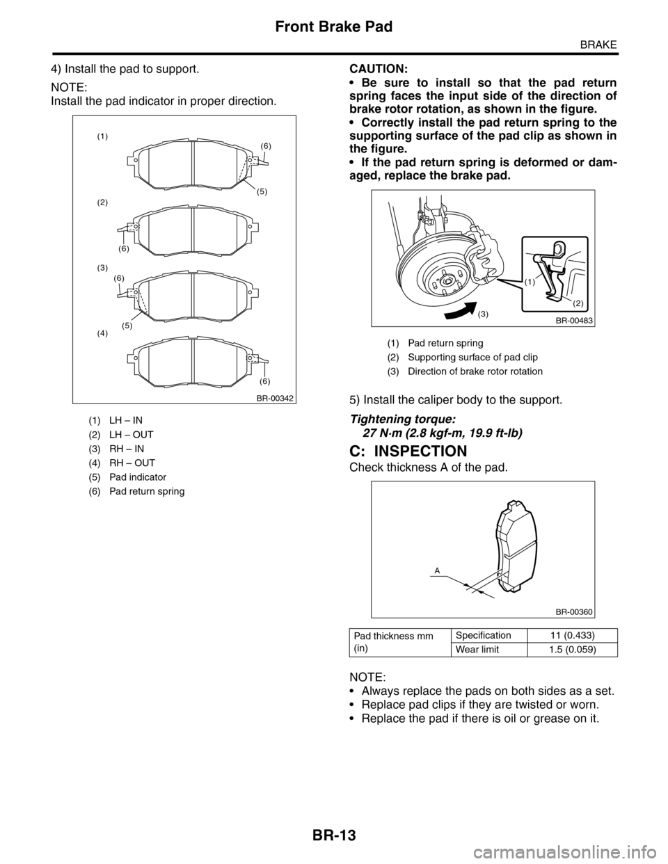
4) Install the pad to support.
NOTE:
Install the pad indicator in proper direction.
CAUTION:
•Be sure to install so that the pad return
spring faces the input side of the direction of
brake rotor rotation, as shown in the figure.
•Correctly install the pad return spring to the
supporting surface of the pad clip as shown in
the figure.
•If the pad return spring is deformed or dam-
aged, replace the brake pad.
5) Install the caliper body to the support.
Tightening torque:
27 N·m (2.8 kgf-m, 19.9 ft-lb)
C: INSPECTION
Check thickness A of the pad.
NOTE:
•Always replace the pads on both sides as a set.
•Replace pad clips if they are twisted or worn.
•Replace the pad if there is oil or grease on it.
(1) LH – IN
(2) LH – OUT
(3) RH – IN
(4) RH – OUT
(5) Pad indicator
(6) Pad return spring
BR-00342
(5)
(6)
(6)
(1)
(2)
(3)
(4)(5)
(6)
(6)
(1) Pad return spring
(2) Suppor ting surface of pad clip
(3) Direction of brake rotor rotation
Pad thickness mm
(in)
Specification 11 (0.433)
Wear limit 1.5 (0.059)
BR-00483
(1)
(2)(3)
BR-00360
A
Page 733 of 2453

BR-19
Rear Brake Pad
BRAKE
5. Rear Brake Pad
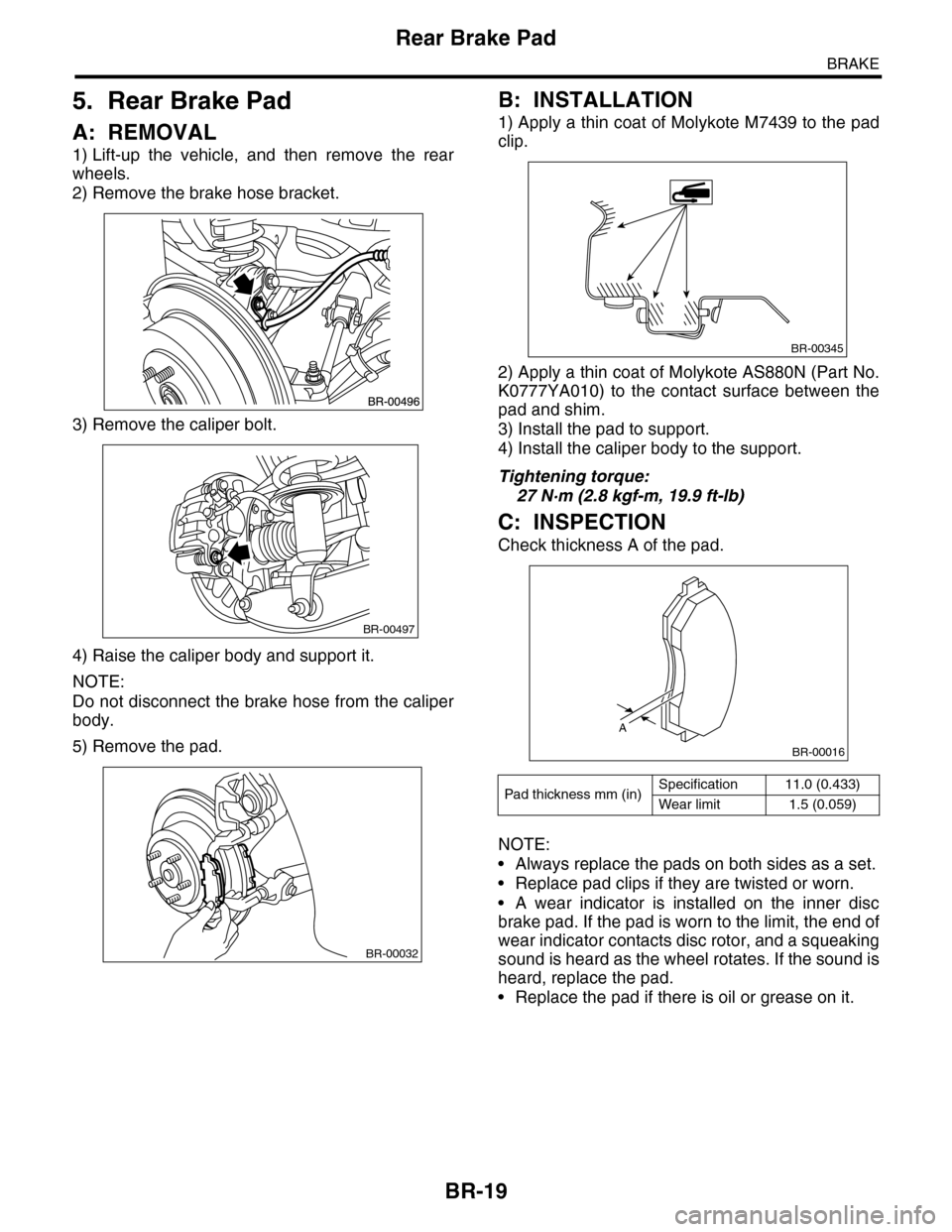
A: REMOVAL
1) Lift-up the vehicle, and then remove the rear
wheels.
2) Remove the brake hose bracket.
3) Remove the caliper bolt.
4) Raise the caliper body and support it.
NOTE:
Do not disconnect the brake hose from the caliper
body.
5) Remove the pad.
B: INSTALLATION
1) Apply a thin coat of Molykote M7439 to the pad
clip.
2) Apply a thin coat of Molykote AS880N (Part No.
K0777YA010) to the contact surface between the
pad and shim.
3) Install the pad to support.
4) Install the caliper body to the support.
Tightening torque:
27 N·m (2.8 kgf-m, 19.9 ft-lb)
C: INSPECTION
Check thickness A of the pad.
NOTE:
•Always replace the pads on both sides as a set.
•Replace pad clips if they are twisted or worn.
•A wear indicator is installed on the inner disc
brake pad. If the pad is worn to the limit, the end of
wear indicator contacts disc rotor, and a squeaking
sound is heard as the wheel rotates. If the sound is
heard, replace the pad.
•Replace the pad if there is oil or grease on it.
BR-00497
BR-00032
Pad thickness mm (in)Specification 11.0 (0.433)
Wear limit 1.5 (0.059)
BR-00345
A
BR-00016