2009 SUBARU TRIBECA Oil spec
[x] Cancel search: Oil specPage 887 of 2453

PS-7
General Description
POWER ASSISTED SYSTEM (POWER STEERING)
C: CAUTION
Please clearly understand and adhere to the following general precautions. They must be strictly followed to
avoid any injury to the person doing the work or people in the area.
1. OPERATION
•Wear work clothing, including a cap, protective goggles and protective shoes during operation.
•Before removal, installation or disassembly, be sure to clarify the failure. Avoid unnecessary removal, in-
stallation, disassembly and replacement.
•Be careful not to burn yourself, because each part on the vehicle is hot after running.
•Use SUBARU genuine power steering fluid, grease etc. or the equivalent. Do not mix fluid, grease etc. with
that of another grade or from other manufacturers.
•Be sure to tighten fasteners including bolts and nuts to the specified torque.
•Place shop jacks or rigid racks at the specified points.
•Before securing a part on a vise, place cushioning material such as wooden blocks, aluminum plate or
cloth between the part and the vise.
2. OIL
When handling oil, follow the rules below to prevent unexpected accidents.
•Prepare container and waste cloths when performing work which oil could possibly spill. If oil spills, wipe
it off immediately to prevent from penetrating into floor or flowing outside, for environmental protection.
•Follow all government and local regulations concerning waste disposal.
D: PREPARATION TOOL
1. SPECIAL TOOL
ILLUSTRATION TOOL NUMBER DESCRIPTION REMARKS
925711000 PRESSURE
GAUGE
Used for measuring oil pressure.
926200000 STAND • Used when inspecting characteristic of gear-
box assembly and disassembling it.
•Used with BOSS D (34199AG000).
ST-925711000
ST-926200000
Page 889 of 2453

PS-9
General Description
POWER ASSISTED SYSTEM (POWER STEERING)
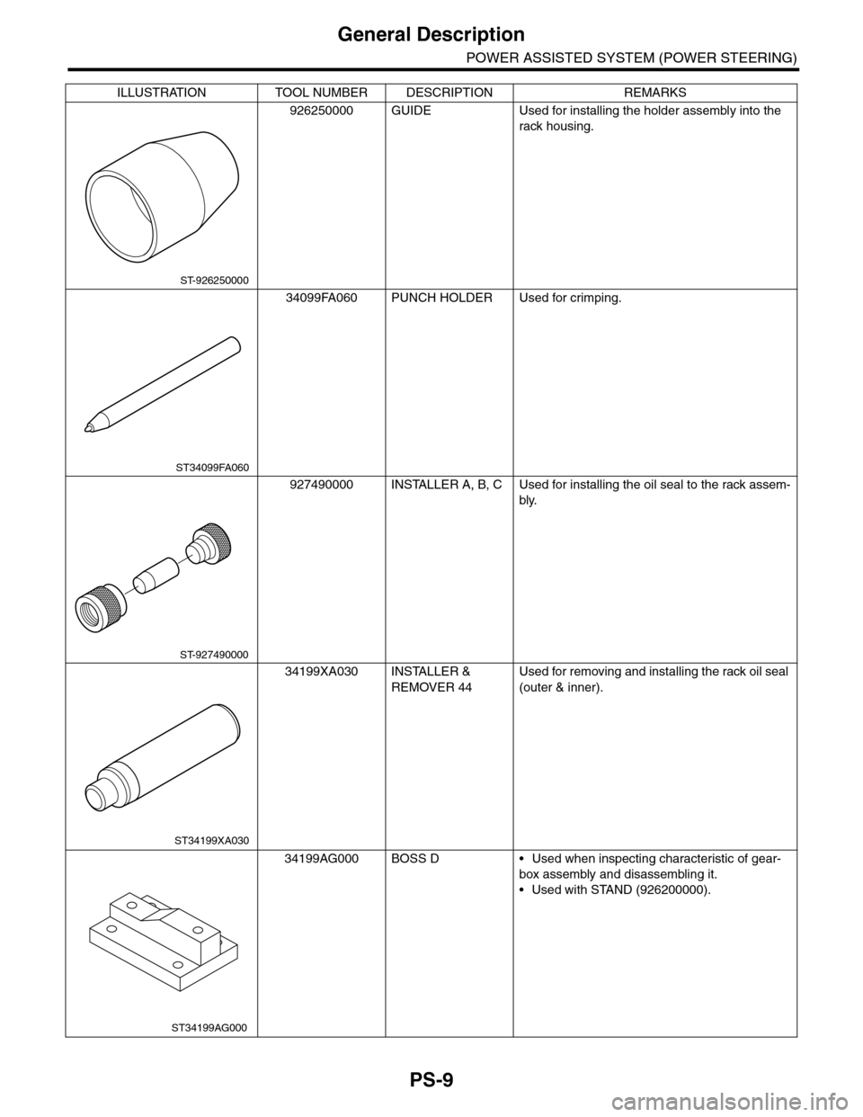
926250000 GUIDE Used for installing the holder assembly into the
rack housing.
34099FA060 PUNCH HOLDER Used for crimping.
927490000 INSTALLER A, B, C Used for installing the oil seal to the rack assem-
bly.
34199XA030 INSTALLER &
REMOVER 44
Used for removing and installing the rack oil seal
(outer & inner).
34199AG000 BOSS D • Used when inspecting characteristic of gear-
box assembly and disassembling it.
•Used with STAND (926200000).
ILLUSTRATION TOOL NUMBER DESCRIPTION REMARKS
ST-926250000
ST34099FA060
ST-927490000
ST34199XA030
ST34199AG000
Page 899 of 2453

PS-19
Steering Gearbox
POWER ASSISTED SYSTEM (POWER STEERING)
6) After tightening the castle nut to the specified
tightening torque, tighten it further within 60° until
the cotter pin hole is aligned with slot in the nut. Fit
the cotter pin into the nut, and then bend the pin to
lock.
7) Install the front stabilizer.
8) Install the front crossmember support plate and
jack-up plate.
9) Install the front exhaust pipe assembly. (Non–
turbo model)
10) Install the under cover.
11) Install the front wheels.
12) Tighten the wheel nuts to the specified torque.
Tightening torque:
110 N·m (11.2 kgf-m, 81.1 ft-lb)
13) Lower the vehicle.
14) Remove the steering wheel.
15) Align the center position of the roll connector.
16) Install the steering wheel.
17) Connect the ground cable to the battery.
18) Pour fluid into the oil tank, and bleed air.
19) Check for fluid leaks.
20) Check the fluid level in oil tank.
21) After adjusting toe-in and steering angle, tight-
en the lock nut on tie-rod end.
Tightening torque:
85 N·m (8.7 kgf-m, 62.7 ft-lb)
NOTE:
When adjusting toe-in, hold the boot as shown to
prevent it from being rotated or twisted. If it be-
comes twisted, straighten it.
C: DISASSEMBLY
1. RACK HOUSING ASSEMBLY
1) Disconnect the four pipes from gearbox.
NOTE:
Remove the pipes C and D, which are fixed to
clamp plate, as a unit.
2) Secure the gearbox removed from vehicle in a
vise using ST.
ST1 926200000 STAND
ST2 34199AG000 BOSS D
CAUTION:
Secure the gearbox in a vise using ST as shown
in the figure. Do not secure the gearbox without
this ST.
3) Remove the tie-rod end and lock nut from gear-
box.
(A) Cotter pin
(B) Castle nut
(C) Tie–rod end
DS-00042
(C)
(B)
(A)
(1) Clamp
PS-00051
PS-00492
(1)
ST1
ST2
Page 909 of 2453

PS-29
Steering Gearbox
POWER ASSISTED SYSTEM (POWER STEERING)
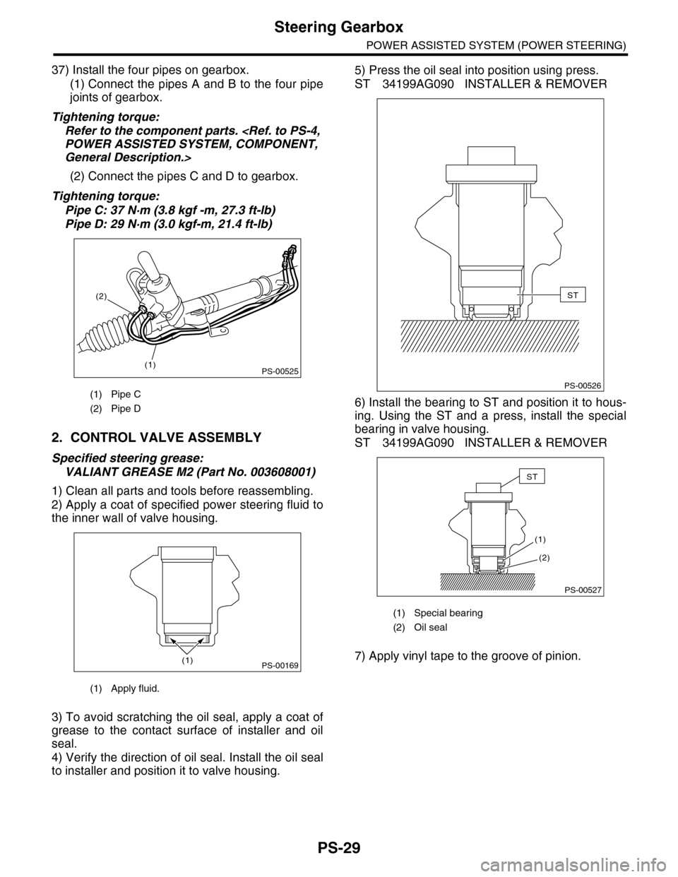
37) Install the four pipes on gearbox.
(1) Connect the pipes A and B to the four pipe
joints of gearbox.
Tightening torque:
Refer to the component parts.
General Description.>
(2) Connect the pipes C and D to gearbox.
Tightening torque:
Pipe C: 37 N·m (3.8 kgf -m, 27.3 ft-lb)
Pipe D: 29 N·m (3.0 kgf-m, 21.4 ft-lb)
2. CONTROL VALVE ASSEMBLY
Specified steering grease:
VALIANT GREASE M2 (Part No. 003608001)
1) Clean all parts and tools before reassembling.
2) Apply a coat of specified power steering fluid to
the inner wall of valve housing.
3) To avoid scratching the oil seal, apply a coat of
grease to the contact surface of installer and oil
seal.
4) Verify the direction of oil seal. Install the oil seal
to installer and position it to valve housing.
5) Press the oil seal into position using press.
ST 34199AG090 INSTALLER & REMOVER
6) Install the bearing to ST and position it to hous-
ing. Using the ST and a press, install the special
bearing in valve housing.
ST 34199AG090 INSTALLER & REMOVER
7) Apply vinyl tape to the groove of pinion.
(1) Pipe C
(2) Pipe D
(1) Apply fluid.
PS-00525(1)
(2)
PS-00169(1)
(1) Special bearing
(2) Oil seal
PS-00526
ST
(2)
(1)
PS-00527
ST
Page 910 of 2453

PS-30
Steering Gearbox
POWER ASSISTED SYSTEM (POWER STEERING)
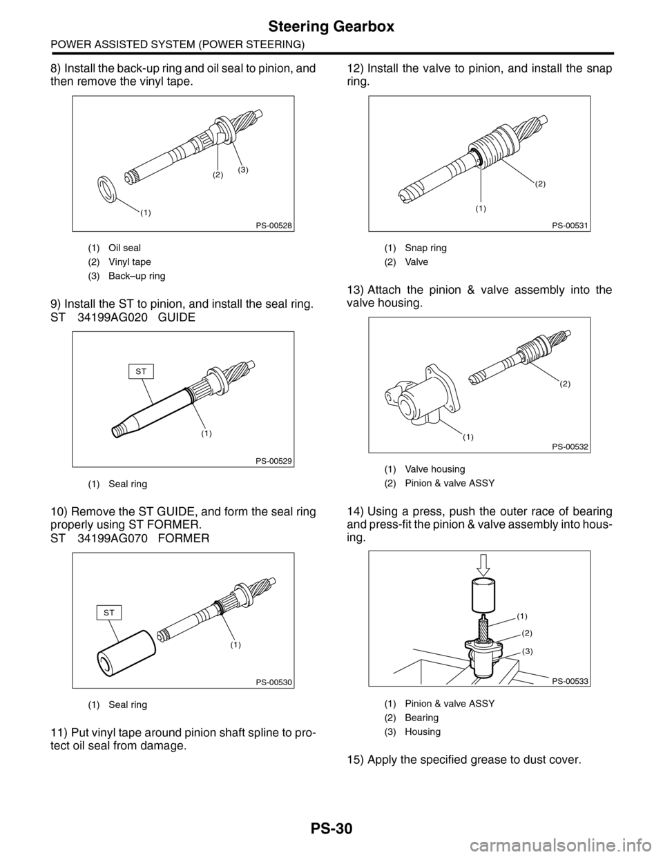
8) Install the back-up ring and oil seal to pinion, and
then remove the vinyl tape.
9) Install the ST to pinion, and install the seal ring.
ST 34199AG020 GUIDE
10) Remove the ST GUIDE, and form the seal ring
properly using ST FORMER.
ST 34199AG070 FORMER
11) Put vinyl tape around pinion shaft spline to pro-
tect oil seal from damage.
12) Install the valve to pinion, and install the snap
ring.
13) Attach the pinion & valve assembly into the
valve housing.
14) Using a press, push the outer race of bearing
and press-fit the pinion & valve assembly into hous-
ing.
15) Apply the specified grease to dust cover.
(1) Oil seal
(2) Vinyl tape
(3) Back–up ring
(1) Seal ring
(1) Seal ring
PS-00528
(1)
(2)(3)
PS-00529
(1)
ST
PS-00530
ST
(1)
(1) Snap ring
(2) Valve
(1) Valve housing
(2) Pinion & valve ASSY
(1) Pinion & valve ASSY
(2) Bearing
(3) Housing
PS-00531
(2)
(1)
PS-00532(1)
(2)
PS-00533
(1)
(2)
(3)
Page 916 of 2453

PS-36
Steering Gearbox
POWER ASSISTED SYSTEM (POWER STEERING)
1) Lift-up the vehicle.
2) If a fluid leak is found, clean the fluid completely
from the suspect area, and turn the steering wheel
approx. 30 to 40 times to the left and right from lock
to lock, with the engine running, and check again
for leaks immediately, and also after a few hours
have passed.
3) Cause and solution for oil leakage from “a”
The oil seal is damaged. Replace the valve assem-
bly with a new one.
4) Cause and solution for oil leakage from “b”.
The torsion bar O–ring is damaged. Replace the
valve assembly with a new one.
5) Cause and solution for oil leakage from “c”.
The oil seal is damaged. Replace the valve assem-
bly or oil seal with a new one.
6) Cause and solution for oil leakage from “d”.
The pipe is damaged. Replace the faulty pipe or O-
ring.
7) Cause and solution for oil leakage from “g”.
The hose is damaged. Replace the hose with a
new one.
8) If leak is other than a, b, c, d or g, or if oil is leak-
ing from gearbox, move the right and left boots to-
ward tie-rod end side, respectively, with the
gearbox mounted to the vehicle, and remove fluid
from surrounding portions. Then, turn the steering
wheel from lock to lock about thirty to forty times
with the engine running, and make comparison of
the leaked portion immediately after and several
hours after this operation.
(1) Leakage from “e”
The cylinder seal is damaged. Replace the rack
bushing with a new one.
(2) Leakage from “f”
There are two possible causes. Perform the fol-
lowing step first. Remove the pipe assembly B
from the valve housing, and close the circuit us-
ing ST.
ST 926420000 PLUG
Turn the steering wheel from lock to lock ap-
prox. 30 to 40 times with the engine running,
then inspect the leaked portion immediately af-
ter and several hours after this operation.
•If leakage from “f” is noted again:
The oil seal of pinion & valve assembly is dam-
aged. Replace the pinion & valve assembly with a
new one. Or replace the oil seal and the parts that
are damaged during disassembly with new ones.
•If oil stops leaking from “f”:
The oil seal of rack housing is damaged. Replace
the oil seal and parts that are damaged during dis-
assembly with new ones.
F: ADJUSTMENT
1) Adjust the front toe.
Standard of front toe:
IN 3 — OUT 3 mm (IN 0.12 — OUT 0.12 in)
2) Adjust the steering angle of the wheels.
Specification of steering angle:
3) If the steering wheel spokes are not horizontal
when wheels are set in the straight ahead position,
or error is more than 5° on the periphery of the
steering wheel, correctly re-install the steering
wheel.
4) If the steering wheel spokes are not horizontal
with vehicle set in the straight ahead position after
this adjustment, correct it by turning the right and
left tie–rods in the opposite direction from each oth-
er by the same angle.
(1) Lock nut
Inner wheel 37.0°±1.5°
Outer wheel 32.0°±1.5°
(1) Within 5°
PS-00107
PS-00513
(1)
Page 918 of 2453

PS-38
Pipe Assembly
POWER ASSISTED SYSTEM (POWER STEERING)
7) Disconnect the suction hose and pressure hose
from oil pump.
8) Disconnect the suction hose and return hose
from the reservoir tank.
9) Remove the oil cooler pipe.
10) Remove the hose bracket and take out the
hose assembly from vehicle.
B: INSTALLATION
1) Install in the reverse order of removal.
Tightening torque:
2) Fill with the specified fluid.
CAUTION:
Never start the engine before feeding the fluid
otherwise the vane pump might be seized.
3) Finally, check the clearance between pipes or
hoses as shown in the figure indicated in “General
Diagnostic Table”.
nostic Table.>
(1) Suction hose
(2) Pressure hose
(1) Reservoir tank
(2) Suction hose
(3) Return hose
PS-00736
(1)
(2)
PS-00737(3)
(2)
(1)
(1) Hose ASSY
(2) Hose bracket
PS-00738
PS-00739
(2)
(1)
Page 919 of 2453

PS-39
Pipe Assembly
POWER ASSISTED SYSTEM (POWER STEERING)
C: INSPECTION
Check all disassembled parts for wear, damage or other problems. Repair or replace the defective parts as
necessary.
CAUTION:
Although the surface layer materials of rubber hoses have excellent weathering resistance, heat re-
sistance and resistance for low temperature brittleness, they are likely to be damaged chemically by
brake fluid, battery electrolyte, engine oil and automatic transmission fluid and their service lives are
to be very shortened. Wipe off hoses immediately if any of these come into contact with the hoses.
Since resistances for heat or low temperature brittleness are gradually declining according to time
accumulation of hot or cold conditions for the hoses and their service lives are shortening accord-
ingly, it is necessary to perform careful inspection frequently when the vehicle is used in hot weather
areas, cold weather areas and a driving condition in which many steering operations are required in
short time.
Particularly continuous work of relief valve over 5 seconds causes to reduce service lives of the hos-
es, the oil pump, the fluid, etc. due to over heat.
Par t Maintenance par ts Corrective action
Pipe
•O–ring fitting surface damage
•Nut damage
•Pipe damage
Replace with a new part.
Clamp • Loose clamps Replace with a new part.
Hose
•Flare surface damage
•Flare nut damage
•Outer surface cracks
•Outer surface wear
•Clip damage
•End coupling or adapter for deformation
Replace with a new part.
Tr o u b l e P o s s i b l e c a u s e C o r r e c t i v e a c t i o n
Pressure hose burst
Excessive holding time of relief status Instruct customers.
Malfunction of the relief valve Replace the oil pump.
Poor cold character istic of fluid R eplace fluid.
Disconnection of the return
hose
Improper connection Repair.
Loosening of the clip Retighten.
Poor cold character istic of fluid R eplace fluid.
Fluid slightly leaking out of
hose
Wrong layout, tensioned Replace the hose.
Excessive play of engine due to deterioration of
engine mounting rubberReplace the parts if defective.
Improper stop position of pitching stopper Replace the parts if defective.
Crack on hose
Excessive holding time of relief statusReplace.
Instruct customers.
Excessive tightening torque for return hose clip Replace.
Power steer ing fluid, engine oil, electrolyte adhere
on the hose surface
Replace.
Be careful during service work.
To o m a n y u s e s i n e x t r e m e l y c o l d w e a t h e rReplace.
Instruct customers.