Page 1891 of 2453
ME(H6DO)-25
Engine Oil Pressure
MECHANICAL
6. Engine Oil Pressure
A: INSPECTION
1) Remove the oil pressure switch from cylinder
block.
Pressure Switch.>
2) Connect the oil pressure gauge hose to cylinder
block.
3) Connect the ground cable to the battery.
4) Start the engine, and measure the oil pressure.
OIL PRESSURE (at oil temperature of 80°C
(176°F)):
Standard:
135 kPa (1.4 kgf/cm2, 20 psi) or more (at
600 rpm)
500 kPa (5.1 kgf/cm2, 73 psi) or more (at
5,000 rpm)
CAUTION:
•If the oil pressure is out of specification,
check oil pump, oil filter and lubrication line.
Diagnostics Table.>
•If the oil pressure warning light is turned ON
and oil pressure is in specification, replace the
oil pressure switch.
SPECTION, General Diagnostics Table.>
5) After measuring the oil pressure, install the oil
pressure switch.
LATION, Oil Pressure Switch.>
Tightening torque:
25 N·m (2.5 kgf-m, 18 ft-lb)
Page 1893 of 2453

ME(H6DO)-27
Valve Clearance
MECHANICAL
8. Valve Clearance
A: INSPECTION
Inspection and adjustment of valve clearance
should be performed while engine is cold.
1) Set the vehicle on a lift.
2) Remove the collector cover.
3) Disconnect the ground cable from battery.
4) Lift-up the vehicle.
5) Remove the under cover.
6) Lower the vehicle.
7) When inspecting RH side cylinders:
(1) Remove the air intake duct and air cleaner
case.
take Duct.>
Air Cleaner Case.>
(2) Remove the fuel tank protector (RH).
(3) Disconnect the connector of oil pressure
switch.
(4) Remove the ignition coil.
IG(H6DO)-7, REMOVAL, Ignition Coil & Ignitor
Assembly.>
(5) Remove the rocker cover (RH).
8) When inspecting LH side cylinders:
(1) Disconnect the battery cable, and then re-
move the battery and battery carrier.
(2) Disconnect the PCV hose and blow-by hose
from rocker cover (LH).
(3) Remove the fuel pipe protector (LH).
(4) Remove the ignition coil.
IG(H6DO)-7, REMOVAL, Ignition Coil & Ignitor
Assembly.>
(5) Remove the rocker cover (LH).
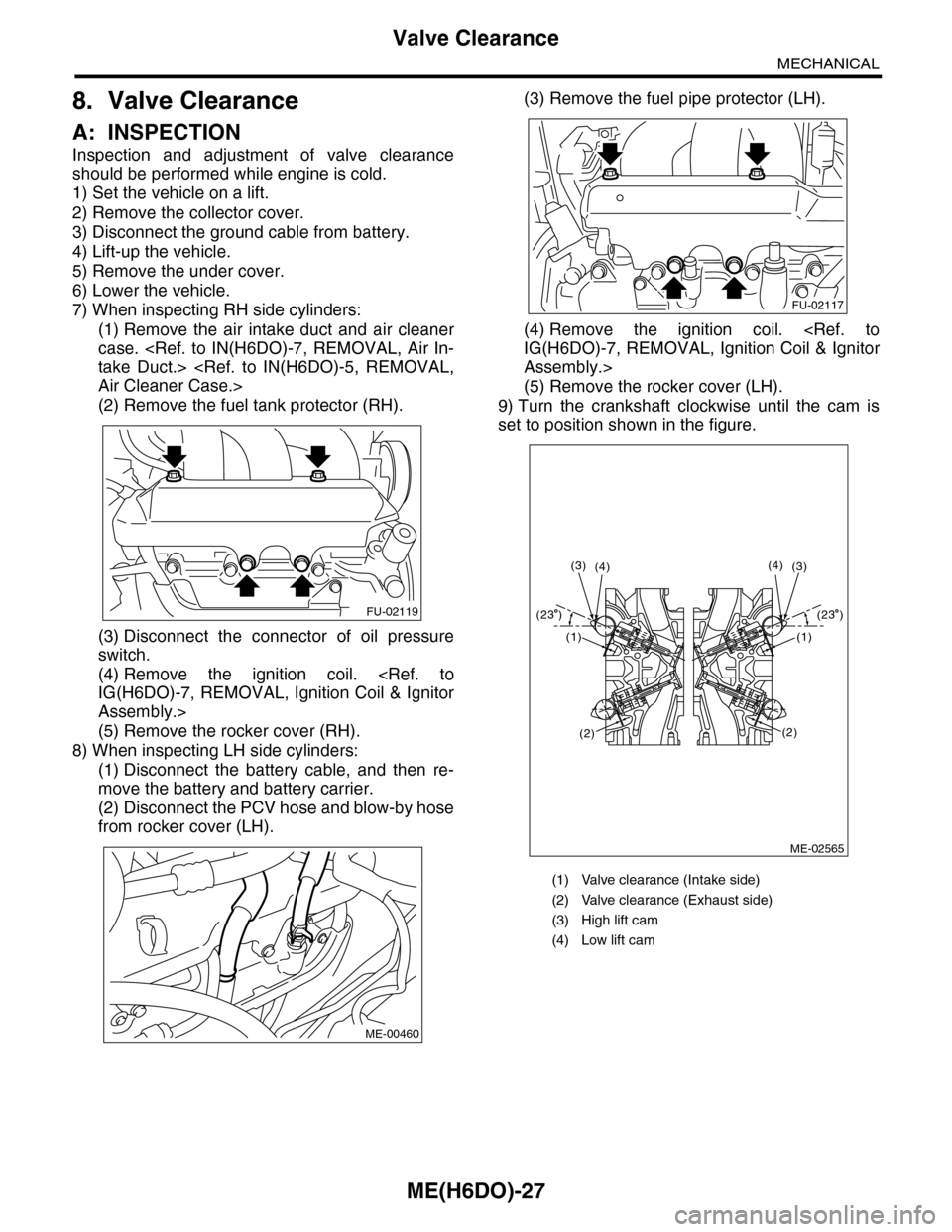
9) Turn the crankshaft clockwise until the cam is
set to position shown in the figure.
FU-02119
ME-00460
(1) Valve clearance (Intake side)
(2) Valve clearance (Exhaust side)
(3) High lift cam
(4) Low lift cam
FU-02117
ME-02565
(4)(3)(3)(4)
(1)
(2)
(1)
(2)
(23 )(23 )
Page 1897 of 2453
ME(H6DO)-31
V-belt
MECHANICAL
9. V-belt
A: REMOVAL
1) Install the tool to belt tension adjuster assembly
installation bolt.
2) Rotate the tool clockwise and loosen the V-belt
to remove.
3) Remove the V-belt cover.
B: INSTALLATION
Install in the reverse order of removal.
C: INSPECTION
1) Replace the V-belt, if cracks, fraying or wear is
found.
2) Make sure that the V-belt automatic belt tension
indicator (A) is within the range (D).
(1) Power steering oil pump pulley
(2) Belt tension adjuster ASSY
(3) Crank pulley
(4) A/C compressor
(5) Belt idler
(6) Generator
ME-00473
(1)(6)
(4)
(5)(2)
(3)ME-00474
(A) Indicator
(B) Generator
(C) Power steering oil pump pulley
(D) Service limit
(B)
(A)
(D)
(C)
ME-00475
Page 1907 of 2453
ME(H6DO)-41
Crank Pulley
MECHANICAL
13.Crank Pulley
A: REMOVAL
1) Remove the crank pulley cover.
2) Remove the crank pulley bolt. To lock the crank-
shaft, use ST.
ST 499977100 CRANK PULLEY WRENCH
3) Remove the crank pulley.
B: INSTALLATION
1) Install the crank pulley.
2) Install the crank pulley bolt. To lock the crank-
shaft, use ST.
ST 499977100 CRANK PULLEY WRENCH
(1) Clean the crank pulley thread using com-
pressed air.
(2) Apply engine oil to the crank pulley bolt seat
and thread.
(3) Tighten the crank pulley bolts.
Tightening torque:
178 N·m (18.1 kgf-m, 131 ft-lb)
3) Install the crank pulley cover.
NOTE:
Assemble the O-ring to crank pulley cover.
Tightening torque:
6.4 N·m (0.65 kgf-m, 4.7 ft-lb)
C: INSPECTION
1) Check the crank pulley cover for oil and air leak-
age.
2) Check the crank pulley for looseness.
ME-02028
ME-00497
ME-00497
ME-02028
Page 1909 of 2453
ME(H6DO)-43
Front Chain Cover
MECHANICAL
4) Tighten the bolts in the numerical order as shown in the figure.
Tightening torque:
6.6 N·m (0.67 kgf-m, 4.8 ft-lb)
5) Install the crank pulley.
C: INSPECTION
Check the cover surface for scratch and damage.
Check for oil leakage on cover mating surface and installation part of crank pulley.
ME-02031
(21)
(22)(40)(39)
(38)
(37)
(36)
(35)
(34)
(33)
(32)(13)(12)(11)
(9)(10)
(23)(24)
(8)
(6)
(25)
(26)
(27)
(28)
(29)(30) (31)(19)
(18)
(17)(16) (15)(14)(20)
(3)
(2)
(4)(5)
(1)
(7)
Page 1921 of 2453

ME(H6DO)-55
Camshaft
MECHANICAL
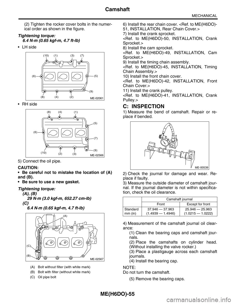
(2) Tighten the rocker cover bolts in the numer-
ical order as shown in the figure.
Tightening torque:
6.4 N·m (0.65 kgf-m, 4.7 ft-lb)
•LH side
•RH side
5) Connect the oil pipe.
CAUTION:
•Be careful not to mistake the location of (A)
and (B).
•Be sure to use a new gasket.
Tightening torque:
(A), (B)
29 N·m (3.0 kgf-m, 652.27 cm-lb)
(C)
6.4 N·m (0.65 kgf-m, 4.7 ft-lb)
6) Install the rear chain cover.
51, INSTALLATION, Rear Chain Cover.>
7) Install the crank sprocket.
Sprocket.>
8) Install the cam sprocket.
Sprocket.>
9) Install the timing chain assembly.
Chain Assembly.>
10) Install the front chain cover.
Chain Cover.>
11) Install the crank pulley.
Pulley.>
C: INSPECTION
1) Measure the bend of camshaft. Repair or re-
place if bended.
2) Check the journal for damage and wear. Re-
place if faulty.
3) Measure the outside diameter of camshaft jour-
nal. If the journal diameter is not within specifica-
tion, check the oil clearance.
4) Measurement of the camshaft journal oil clear-
ance:
(1) Clean the bearing caps and camshaft jour-
nals.
(2) Place the camshafts on cylinder head.
(Without installing the valve rocker.)
(3) Place a plastigauge across each camshaft
journals.
(4) Install the bearing cap.
NOTE:
Do not turn the camshaft.
(5) Remove the bearing caps.
(A) Bolt without filter (with white mark)
(B) Bolt with filter (without white mark)
(C) Oil pipe bolt
ME-02061(2)
(7)(3)(1)(10)
(6)
(8)(4)
(5)
(9)
ME-02566
(8)(4)(1)
(5)
(7)
(9)(3)(2)
(6)
(10)
ME-02567
(A)
(C)
(B)
Camshaft journal
Front Except for front
Standard
mm (in)
37.946 — 37.963
(1.4939 — 1.4946)
25.946 — 25.963
(1.0215 — 1.0222)
ME-00539
Page 1924 of 2453

ME(H6DO)-58
Cylinder Head
MECHANICAL
8) Install the front chain cover.
Chain Cover.>
9) Install the crank pulley.
Pulley.>
C: DISASSEMBLY
1) Set the cylinder head on ST.
ST 18250AA010 CYLINDER HEAD TABLE
2) Remove the valve lifter.
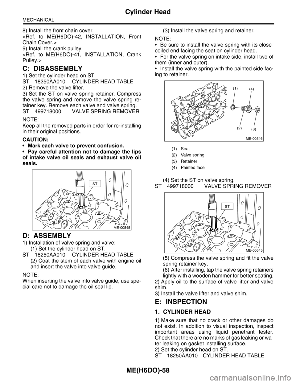
3) Set the ST on valve spring retainer. Compress
the valve spring and remove the valve spring re-
tainer key. Remove each valve and valve spring.
ST 499718000 VALVE SPRING REMOVER
NOTE:
Keep all the removed parts in order for re-installing
in their original positions.
CAUTION:
•Mark each valve to prevent confusion.
•Pay careful attention not to damage the lips
of intake valve oil seals and exhaust valve oil
seals.
D: ASSEMBLY
1) Installation of valve spring and valve:
(1) Set the cylinder head on ST.
ST 18250AA010 CYLINDER HEAD TABLE
(2) Coat the stem of each valve with engine oil
and insert the valve into valve guide.
NOTE:
When inserting the valve into valve guide, use spe-
cial care not to damage the oil seal lip.
(3) Install the valve spring and retainer.
NOTE:
•Be sure to install the valve spring with its close-
coiled end facing the seat on cylinder head.
•For the valve spring on intake side, install two of
them (inner and outer).
•Install the valve spring with the painted side fac-
ing to retainer.
(4) Set the ST on valve spring.
ST 499718000 VALVE SPRING REMOVER
(5) Compress the valve spring and fit the valve
spring retainer key.
(6) After installing, tap the valve spring retainers
lightly with a wooden hammer for better seating.
2) Apply oil to the surface of valve lifter and valve
shim.
3) Install the valve lifter and valve shim.
E: INSPECTION
1. CYLINDER HEAD
1) Make sure that no crack or other damages do
not exist. In addition to visual inspection, inspect
important areas using liquid penetrant tester.
Check that there are no marks of gas leaking or wa-
ter leaking on gasket installing surface.
2) Set the cylinder head on ST.
ST 18250AA010 CYLINDER HEAD TABLE
ST
ME-00545
(1) Seat
(2) Valve spring
(3) Retainer
(4) Painted face
(1)
(2)(3)
(4)
ME-00546
ST
ME-00545
Page 1926 of 2453

ME(H6DO)-60
Cylinder Head
MECHANICAL
(3) Turn the cylinder head upside down and
place the ST as shown in the figure.
ST 18251AA040 VALVE GUIDE ADJUSTER
(4) Before installing a new valve guide, make
sure that neither scratches nor damages exist
on the inner surface of valve guide holes in cyl-
inder head.
(5) Put a new valve guide, coated with sufficient
oil, in cylinder, and insert the ST1 into valve
guide. Press in until the valve guide upper end
is flush with the upper surface of ST2.
ST1 499765700 VALVE GUIDE REMOVER
ST2 18251AA040 VALVE GUIDE ADJUSTER
(6) Check the valve guide protrusion.
Valve guide protrusion L:
11.4 — 11.8 mm (0.449 — 0.465 in)
(7) Ream the inside of valve guide using ST.
Put the reamer in valve guide, and rotate the
reamer slowly clockwise while pushing it lightly.
Bring the reamer back while rotating it clock-
wise. After reaming, clean the valve guide to re-
move chips.
ST 499765900 VALVE GUIDE REAMER
NOTE:
•Apply engine oil to the reamer when reaming.
•If the inner surface of valve guide is damaged,
the edge of reamer should be slightly ground with
oil stone.
•If the inner surface of valve guide becomes lus-
trous and the reamer does not chip, use a new
reamer or remedy the reamer.
(8) Recheck the contact condition between
valve and valve seat after replacing the valve
guide.
4. INTAKE AND EXHAUST VALVE
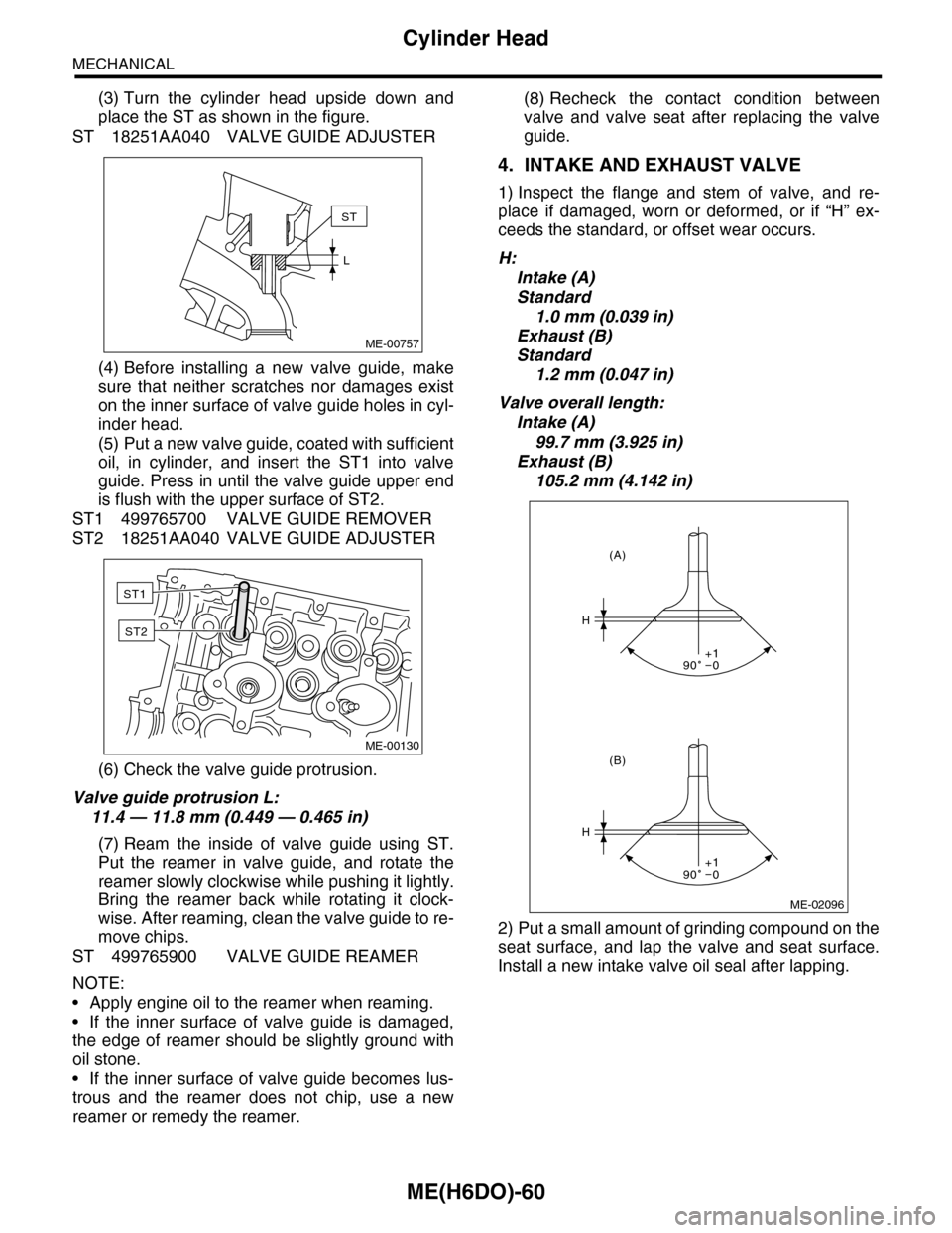
1) Inspect the flange and stem of valve, and re-
place if damaged, worn or deformed, or if “H” ex-
ceeds the standard, or offset wear occurs.
H:
Intake (A)
Standard
1.0 mm (0.039 in)
Exhaust (B)
Standard
1.2 mm (0.047 in)
Valve overall length:
Intake (A)
99.7 mm (3.925 in)
Exhaust (B)
105.2 mm (4.142 in)
2) Put a small amount of grinding compound on the
seat surface, and lap the valve and seat surface.
Install a new intake valve oil seal after lapping.
ME-00757
ST
L
ME-00130
ST1
ST2
ME-02096
H
H
(B)
(A)
90 0+1
90 0+1