2009 SUBARU TRIBECA Oil spec
[x] Cancel search: Oil specPage 1927 of 2453
ME(H6DO)-61
Cylinder Head
MECHANICAL
5. VALVE SPRING
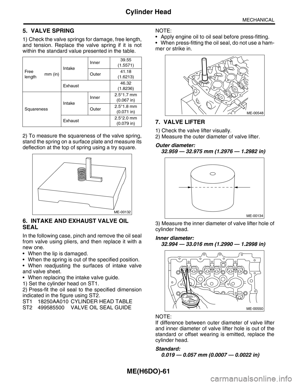
1) Check the valve springs for damage, free length,
and tension. Replace the valve spring if it is not
within the standard value presented in the table.
2) To measure the squareness of the valve spring,
stand the spring on a surface plate and measure its
deflection at the top of spring using a try square.
6. INTAKE AND EXHAUST VALVE OIL
SEAL
In the following case, pinch and remove the oil seal
from valve using pliers, and then replace it with a
new one.
•When the lip is damaged.
•When the spring is out of the specified position.
•When readjusting the surfaces of intake valve
and valve sheet.
•When replacing the intake valve guide.
1) Set the cylinder head on ST1.
2) Press-fit the oil seal to the specified dimension
indicated in the figure using ST2.
ST1 18250AA010 CYLINDER HEAD TABLE
ST2 499585500 VALVE OIL SEAL GUIDE
NOTE:
•Apply engine oil to oil seal before press-fitting.
•When press-fitting the oil seal, do not use a ham-
mer or strike in.
7. VALVE LIFTER
1) Check the valve lifter visually.
2) Measure the outer diameter of valve lifter.
Outer diameter:
32.959 — 32.975 mm (1.2976 — 1.2982 in)
3) Measure the inner diameter of valve lifter hole of
cylinder head.
Inner diameter:
32.994 — 33.016 mm (1.2990 — 1.2998 in)
NOTE:
If difference between outer diameter of valve lifter
and inner diameter of valve lifter hole is out of the
standard or offset wearing is emitted, replace the
cylinder head.
Standard:
0.019 — 0.057 mm (0.0007 — 0.0022 in)
Fr e e
lengthmm (in)
Intake
Inner39.55
(1.5571)
Outer41.18
(1.6213)
Exhaust46.32
(1.8236)
Squareness
Intake
Inner2.5°1.7 mm
(0.067 in)
Outer2.5°1.8 mm
(0.071 in)
Exhaust2.5°2.0 mm
(0.079 in)
ME-00132
ME-00548
ME-00134
ME-00550
Page 1937 of 2453
ME(H6DO)-71
Cylinder Block
MECHANICAL
E: INSPECTION
1. CYLINDER BLOCK
1) Visually check for cracks and damage. Especial-
ly, inspect the important parts using liquid pene-
trant tester.
2) Check the oil passages for clogging.
3) Inspect the crankcase surface that mates with
cylinder head for warping by using a straight edge.
Standard height of cylinder block:
202 mm (7.95 in)
2. CYLINDER AND PISTON
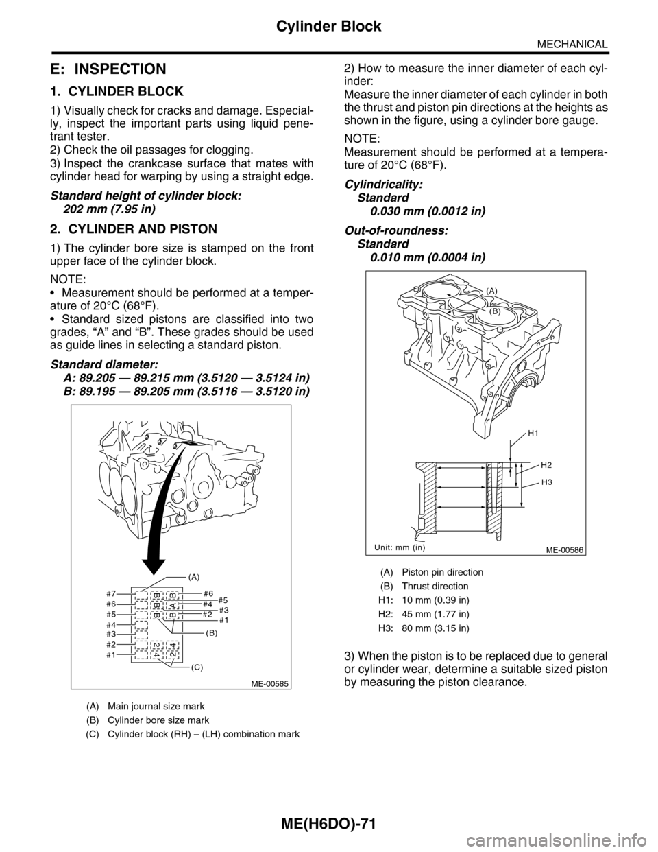
1) The cylinder bore size is stamped on the front
upper face of the cylinder block.
NOTE:
•Measurement should be performed at a temper-
ature of 20°C (68°F).
•Standard sized pistons are classified into two
grades, “A” and “B”. These grades should be used
as guide lines in selecting a standard piston.
Standard diameter:
A: 89.205 — 89.215 mm (3.5120 — 3.5124 in)
B: 89.195 — 89.205 mm (3.5116 — 3.5120 in)
2) How to measure the inner diameter of each cyl-
inder:
Measure the inner diameter of each cylinder in both
the thrust and piston pin directions at the heights as
shown in the figure, using a cylinder bore gauge.
NOTE:
Measurement should be performed at a tempera-
ture of 20°C (68°F).
Cylindricality:
Standard
0.030 mm (0.0012 in)
Out-of-roundness:
Standard
0.010 mm (0.0004 in)
3) When the piston is to be replaced due to general
or cylinder wear, determine a suitable sized piston
by measuring the piston clearance.
(A) Main journal size mark
(B) Cylinder bore size mark
(C) Cylinder block (RH) – (LH) combination mark
#7 #6#5
#2#1
#4#3#6#5#4#3#2#1
BBB 2
42BAB4
(A)
(B)
(C)
ME-00585
(A) Piston pin direction
(B) Thrust direction
H1: 10 mm (0.39 in)
H2: 45 mm (1.77 in)
H3: 80 mm (3.15 in)
ME-00586
H1
H2
H3
Unit: mm (in)
(B)
(A)
Page 1940 of 2453
ME(H6DO)-74
Cylinder Block
MECHANICAL
5. CONNECTING ROD
1) Replace the connecting rod, if the large or small
end thrust surface is damaged.
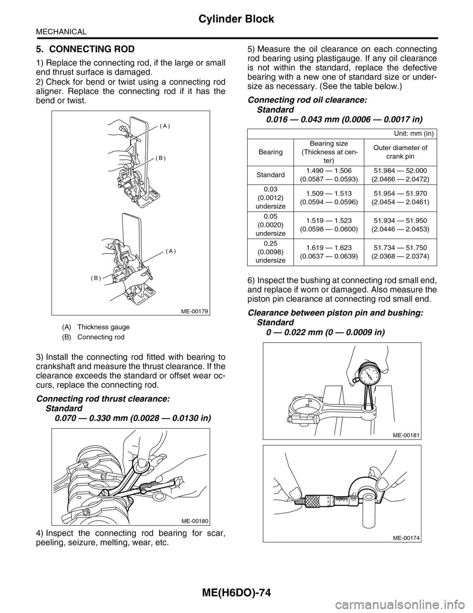
2) Check for bend or twist using a connecting rod
aligner. Replace the connecting rod if it has the
bend or twist.
3) Install the connecting rod fitted with bearing to
crankshaft and measure the thrust clearance. If the
clearance exceeds the standard or offset wear oc-
curs, replace the connecting rod.
Connecting rod thrust clearance:
Standard
0.070 — 0.330 mm (0.0028 — 0.0130 in)
4) Inspect the connecting rod bearing for scar,
peeling, seizure, melting, wear, etc.
5) Measure the oil clearance on each connecting
rod bearing using plastigauge. If any oil clearance
is not within the standard, replace the defective
bearing with a new one of standard size or under-
size as necessary. (See the table below.)
Connecting rod oil clearance:
Standard
0.016 — 0.043 mm (0.0006 — 0.0017 in)
6) Inspect the bushing at connecting rod small end,
and replace if worn or damaged. Also measure the
piston pin clearance at connecting rod small end.
Clearance between piston pin and bushing:
Standard
0 — 0.022 mm (0 — 0.0009 in)(A) Thickness gauge
(B) Connecting rod
(A)
(A)
(B)
(B)
ME-00179
ME-00180
Unit: mm (in)
Bearing
Bearing size
(Thickness at cen-
ter)
Outer diameter of
crank pin
Standard1.490 — 1.506
(0.0587 — 0.0593)
51.984 — 52.000
(2.0466 — 2.0472)
0.03
(0.0012)
undersize
1.509 — 1.513
(0.0594 — 0.0596)
51.954 — 51.970
(2.0454 — 2.0461)
0.05
(0.0020)
undersize
1.519 — 1.523
(0.0598 — 0.0600)
51.934 — 51.950
(2.0446 — 2.0453)
0.25
(0.0098)
undersize
1.619 — 1.623
(0.0637 — 0.0639)
51.734 — 51.750
(2.0368 — 2.0374)
ME-00181
ME-00174
Page 1941 of 2453
ME(H6DO)-75
Cylinder Block
MECHANICAL
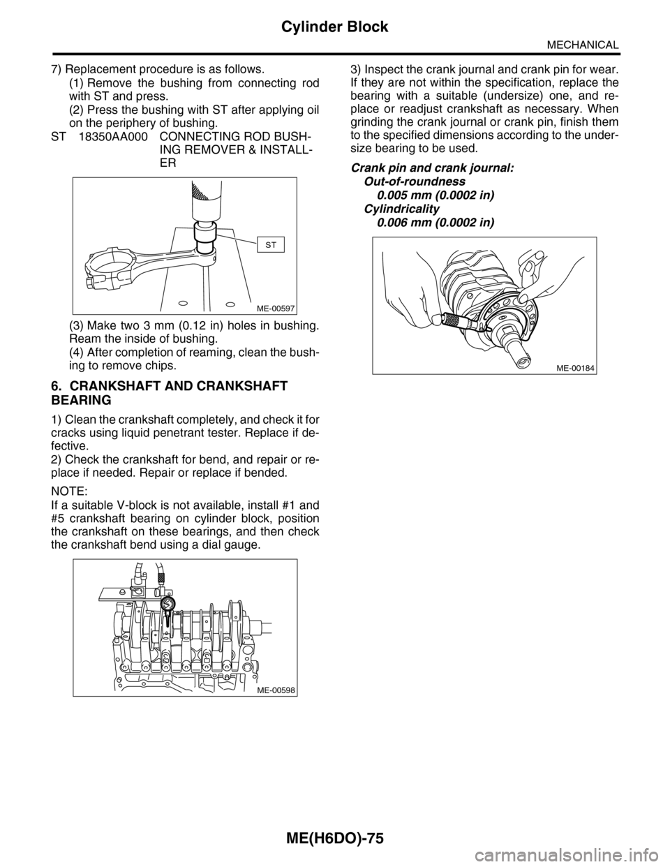
7) Replacement procedure is as follows.
(1) Remove the bushing from connecting rod
with ST and press.
(2) Press the bushing with ST after applying oil
on the periphery of bushing.
ST 18350AA000 CONNECTING ROD BUSH-
ING REMOVER & INSTALL-
ER
(3) Make two 3 mm (0.12 in) holes in bushing.
Ream the inside of bushing.
(4) After completion of reaming, clean the bush-
ing to remove chips.
6. CRANKSHAFT AND CRANKSHAFT
BEARING
1) Clean the crankshaft completely, and check it for
cracks using liquid penetrant tester. Replace if de-
fective.
2) Check the crankshaft for bend, and repair or re-
place if needed. Repair or replace if bended.
NOTE:
If a suitable V-block is not available, install #1 and
#5 crankshaft bearing on cylinder block, position
the crankshaft on these bearings, and then check
the crankshaft bend using a dial gauge.
3) Inspect the crank journal and crank pin for wear.
If they are not within the specification, replace the
bearing with a suitable (undersize) one, and re-
place or readjust crankshaft as necessary. When
grinding the crank journal or crank pin, finish them
to the specified dimensions according to the under-
size bearing to be used.
Crank pin and crank journal:
Out-of-roundness
0.005 mm (0.0002 in)
Cylindricality
0.006 mm (0.0002 in)
ST
ME-00597
ME-00598
ME-00184
Page 1942 of 2453
ME(H6DO)-76
Cylinder Block
MECHANICAL
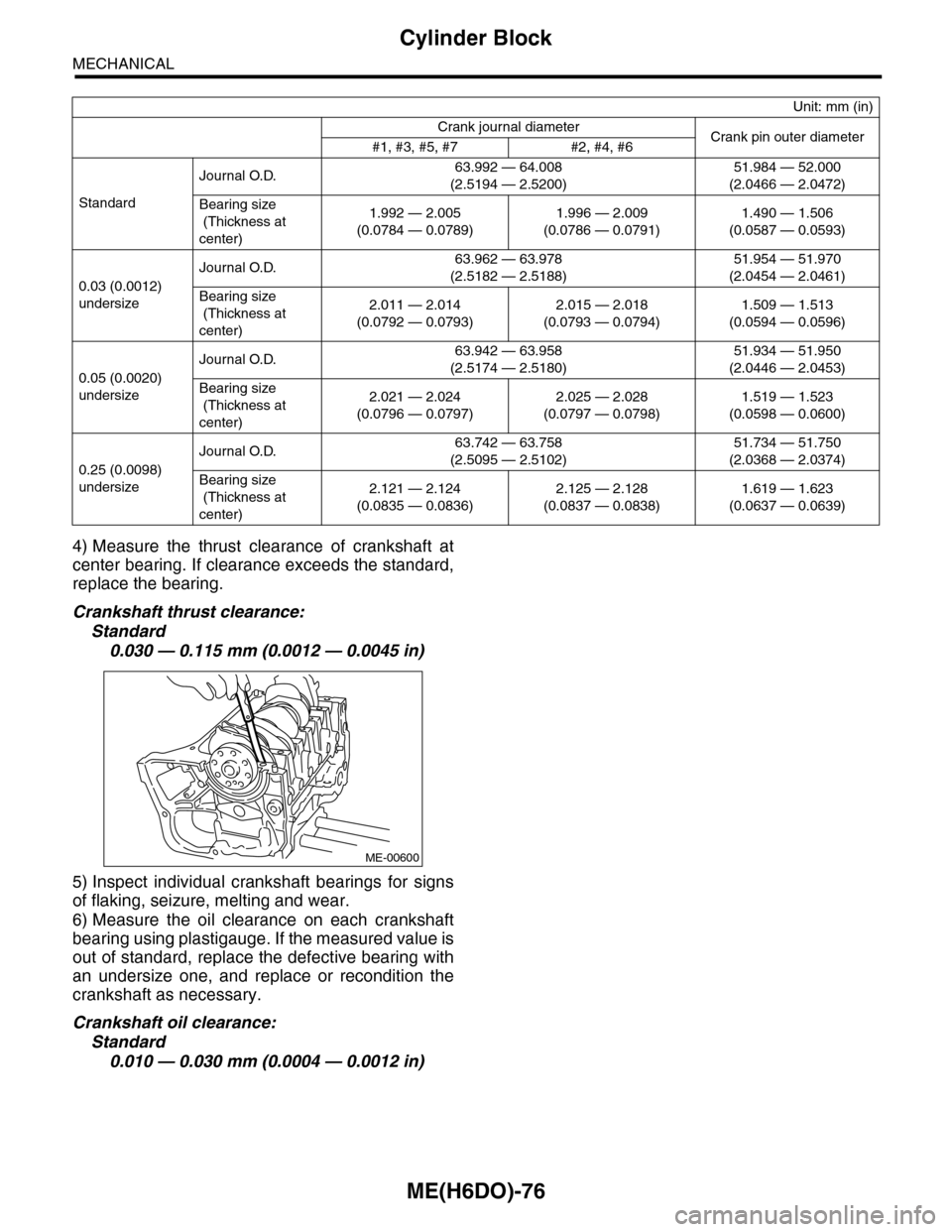
4) Measure the thrust clearance of crankshaft at
center bearing. If clearance exceeds the standard,
replace the bearing.
Crankshaft thrust clearance:
Standard
0.030 — 0.115 mm (0.0012 — 0.0045 in)
5) Inspect individual crankshaft bearings for signs
of flaking, seizure, melting and wear.
6) Measure the oil clearance on each crankshaft
bearing using plastigauge. If the measured value is
out of standard, replace the defective bearing with
an undersize one, and replace or recondition the
crankshaft as necessary.
Crankshaft oil clearance:
Standard
0.010 — 0.030 mm (0.0004 — 0.0012 in)
Unit: mm (in)
Crank journal diameterCrank pin outer diameter#1, #3, #5, #7 #2, #4, #6
Standard
Journal O.D.63.992 — 64.008
(2.5194 — 2.5200)
51.984 — 52.000
(2.0466 — 2.0472)
Bearing size
(Thickness at
center)
1.992 — 2.005
(0.0784 — 0.0789)
1.996 — 2.009
(0.0786 — 0.0791)
1.490 — 1.506
(0.0587 — 0.0593)
0.03 (0.0012)
undersize
Journal O.D.63.962 — 63.978
(2.5182 — 2.5188)
51.954 — 51.970
(2.0454 — 2.0461)
Bearing size
(Thickness at
center)
2.011 — 2.014
(0.0792 — 0.0793)
2.015 — 2.018
(0.0793 — 0.0794)
1.509 — 1.513
(0.0594 — 0.0596)
0.05 (0.0020)
undersize
Journal O.D.63.942 — 63.958
(2.5174 — 2.5180)
51.934 — 51.950
(2.0446 — 2.0453)
Bearing size
(Thickness at
center)
2.021 — 2.024
(0.0796 — 0.0797)
2.025 — 2.028
(0.0797 — 0.0798)
1.519 — 1.523
(0.0598 — 0.0600)
0.25 (0.0098)
undersize
Journal O.D.63.742 — 63.758
(2.5095 — 2.5102)
51.734 — 51.750
(2.0368 — 2.0374)
Bearing size
(Thickness at
center)
2.121 — 2.124
(0.0835 — 0.0836)
2.125 — 2.128
(0.0837 — 0.0838)
1.619 — 1.623
(0.0637 — 0.0639)
ME-00600
Page 1949 of 2453
ME(H6DO)-83
Engine Trouble in General
MECHANICAL
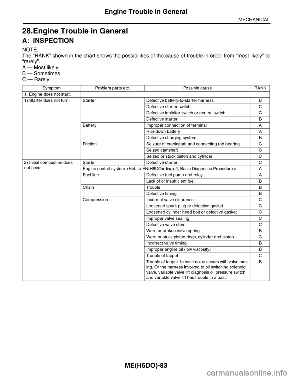
28.Engine Trouble in General
A: INSPECTION
NOTE:
The “RANK” shown in the chart shows the possibilities of the cause of trouble in order from “most likely” to
“rarely”.
A — Most likely
B — Sometimes
C — Rarely
Symptom Problem parts etc. Possible cause RANK
1. Engine does not start.
1) Starter does not turn. Starter Defective battery-to-starter harness B
Defective starter switch C
Defective inhibitor switch or neutral switch C
Defective starter B
Battery Improper connection of terminal A
Run-down battery A
Defective charging system B
Fr iction Seizure of crankshaft and connecting rod bear ing C
Seized camshaft C
Seized or stuck piston and cylinder C
2) Initial combustion does
not occur.
Starter Defective starter C
Engine control system
Fuel line Defective fuel pump and relay A
Lack of or insufficient fuel B
Chain Trouble B
Defective timing B
Compression Incorrect valve clearance C
Loosened spark plug or defective gasket C
Loosened cylinder head bolt or defective gasket C
Improper valve sealing C
Defective valve stem C
Wor n or broken valve spr ing B
Wor n or stuck piston r ings, cylinder and piston C
Incorrect valve timing B
Improper engine oil (low viscosity) B
Tr o u b l e o f t a p p e t C
Tr o u b l e o f t a p p e t . I n c a s e n o i s e o c c u r s w i t h v a l v e m o v -
ing. Or the harness involved to oil switching solenoid
valve, variable valve lift diagnosis oil pressure switch
and variable valve lift has trouble in a past.
B
Page 1956 of 2453
ME(H6DO)-90
Engine Noise
MECHANICAL
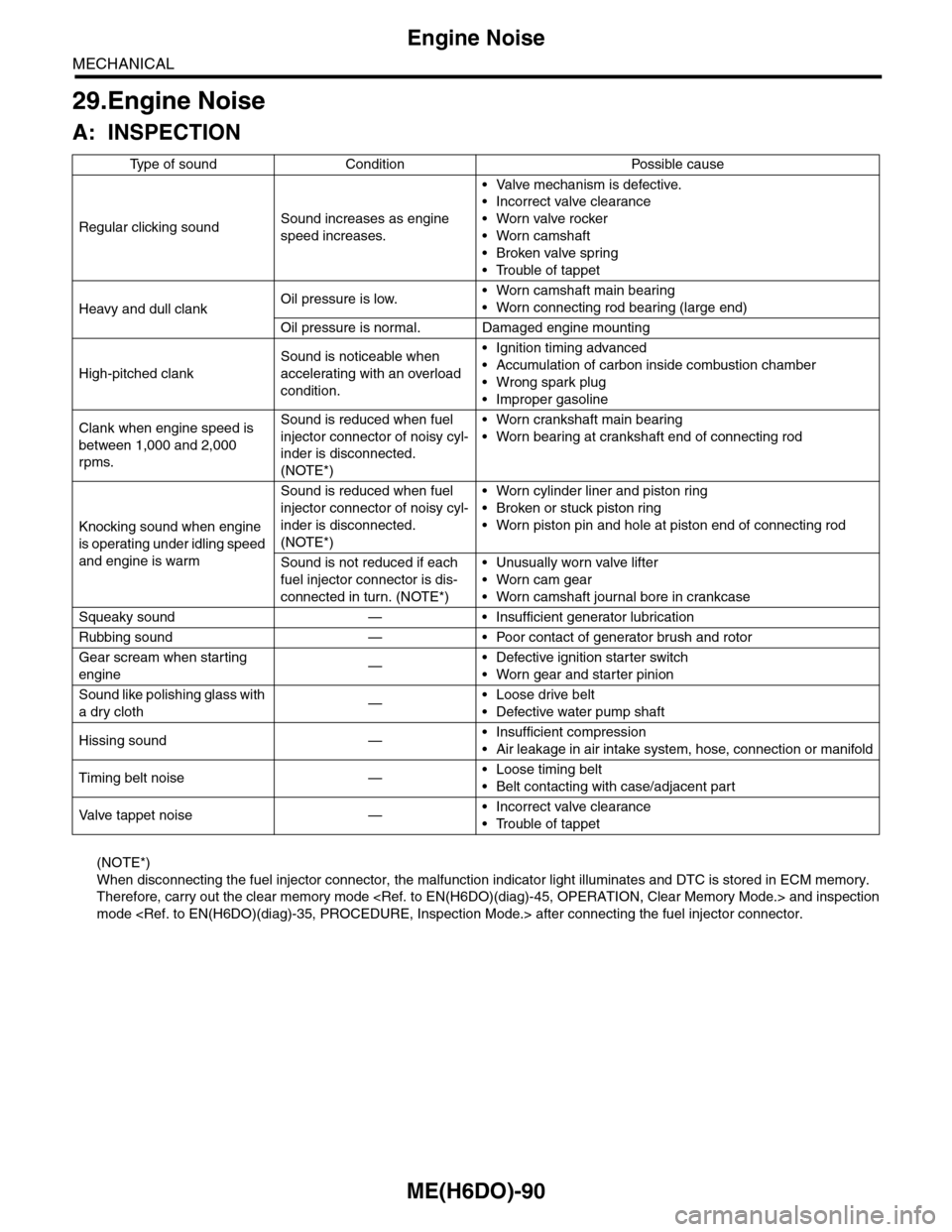
29.Engine Noise
A: INSPECTION
(NOTE*)
When disconnecting the fuel injector connector, the malfunction indicator light illuminates and DTC is stored in ECM memory.
Therefore, carry out the clear memory mode
mode
Ty p e o f s o u n d C o n d i t i o n P o s s i b l e c a u s e
Regular clicking soundSound increases as engine
speed increases.
•Valve mechanism is defective.
•Incorrect valve clearance
•Worn valve rocker
•Worn camshaft
•Broken valve spring
•Trouble of tappet
Heavy and dull clankOil pressure is low.•Worn camshaft main bearing
•Worn connecting rod bearing (large end)
Oil pressure is normal. Damaged engine mounting
High-pitched clank
Sound is noticeable when
accelerating with an overload
condition.
•Ignition timing advanced
•Accumulation of carbon inside combustion chamber
•Wrong spark plug
•Improper gasoline
Clank when engine speed is
between 1,000 and 2,000
rpms.
Sound is reduced when fuel
injector connector of noisy cyl-
inder is disconnected.
(NOTE*)
•Worn crankshaft main bearing
•Worn bearing at crankshaft end of connecting rod
Knocking sound when engine
is operating under idling speed
and engine is warm
Sound is reduced when fuel
injector connector of noisy cyl-
inder is disconnected.
(NOTE*)
•Worn cylinder liner and piston ring
•Broken or stuck piston ring
•Worn piston pin and hole at piston end of connecting rod
Sound is not reduced if each
fuel injector connector is dis-
connected in turn. (NOTE*)
•Unusually worn valve lifter
•Worn cam gear
•Worn camshaft journal bore in crankcase
Squeaky sound — • Insufficient generator lubrication
Rubbing sound — • Poor contact of generator brush and rotor
Gear scream when starting
engine—•Defective ignition starter switch
•Worn gear and starter pinion
Sound like polishing glass with
a dry cloth—•Loose drive belt
•Defective water pump shaft
Hissing sound —•Insufficient compression
•Air leakage in air intake system, hose, connection or manifold
Timing belt noise —•Loose timing belt
•Belt contacting with case/adjacent part
Va l ve t a p p e t n o i s e —•Incorrect valve clearance
•Trouble of tappet
Page 1973 of 2453
SC(H6DO)-15
Starter
STARTING/CHARGING SYSTEMS
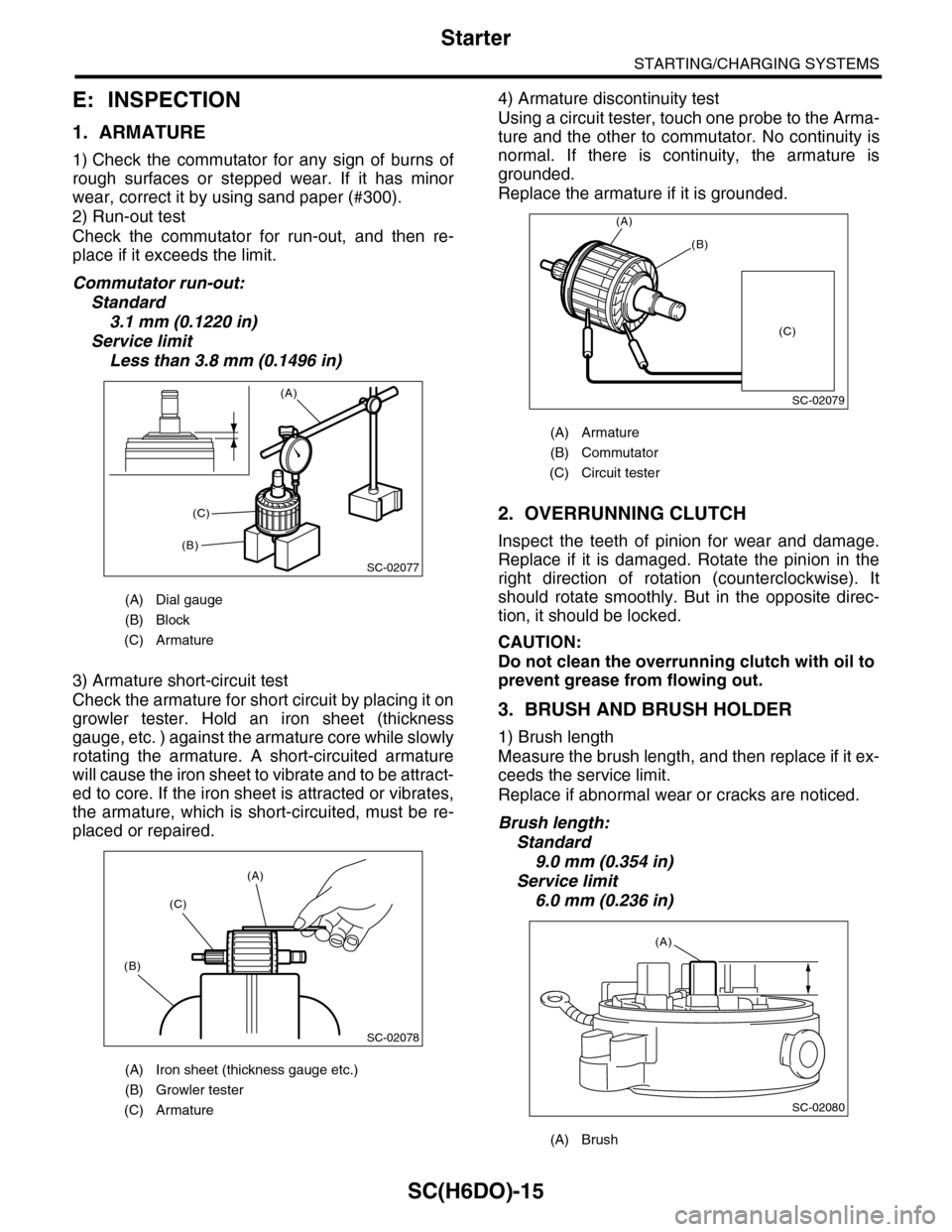
E: INSPECTION
1. ARMATURE
1) Check the commutator for any sign of burns of
rough surfaces or stepped wear. If it has minor
wear, correct it by using sand paper (#300).
2) Run-out test
Check the commutator for run-out, and then re-
place if it exceeds the limit.
Commutator run-out:
Standard
3.1 mm (0.1220 in)
Service limit
Less than 3.8 mm (0.1496 in)
3) Armature short-circuit test
Check the armature for short circuit by placing it on
growler tester. Hold an iron sheet (thickness
gauge, etc. ) against the armature core while slowly
rotating the armature. A short-circuited armature
will cause the iron sheet to vibrate and to be attract-
ed to core. If the iron sheet is attracted or vibrates,
the armature, which is short-circuited, must be re-
placed or repaired.
4) Armature discontinuity test
Using a circuit tester, touch one probe to the Arma-
ture and the other to commutator. No continuity is
normal. If there is continuity, the armature is
grounded.
Replace the armature if it is grounded.
2. OVERRUNNING CLUTCH
Inspect the teeth of pinion for wear and damage.
Replace if it is damaged. Rotate the pinion in the
right direction of rotation (counterclockwise). It
should rotate smoothly. But in the opposite direc-
tion, it should be locked.
CAUTION:
Do not clean the overrunning clutch with oil to
prevent grease from flowing out.
3. BRUSH AND BRUSH HOLDER
1) Brush length
Measure the brush length, and then replace if it ex-
ceeds the service limit.
Replace if abnormal wear or cracks are noticed.
Brush length:
Standard
9.0 mm (0.354 in)
Service limit
6.0 mm (0.236 in)
(A) Dial gauge
(B) Block
(C) Armature
(A) Iron sheet (thickness gauge etc.)
(B) Growler tester
(C) Armature
SC-02077
(A)
(B)
(C)
SC-02078
(A)
(C)
(B)
(A) Armature
(B) Commutator
(C) Circuit tester
(A) Brush
SC-02079
(A)
(B)
(C)
SC-02080
(A)