Page 1839 of 2453
IG(H6DO)-4
Spark Plug
IGNITION
2. Spark Plug
A: REMOVAL
CAUTION:
All spark plugs installed on an engine must be
of the same heat range.
Spark plug:
al Description.>
1. RH SIDE
1) Remove the collector cover.
2) Disconnect the ground cable from battery.
3) Remove the air cleaner case.
Case.>
4) Remove the bracket.
5) Disconnect the connector from ignition coil.
6) Remove the ignition coil.
NOTE:
Turn the #5 ignition coil to remove it.
7) Remove the spark plug with a spark plug socket.
2. LH SIDE
1) Remove the collector cover.
2) Remove the battery and battery carrier.
3) Remove the bracket.
4) Disconnect the connector from ignition coil.
5) Remove the ignition coil.
NOTE:
Turn the #6 ignition coil to remove it.
(A) Bracket
(B) Connector
IG-02004(B)
(A)
(A) Ratchet handle
(B) Extension bar
(C) Universal joint
(D) Spark plug socket
(A) Bracket
(B) Connector
IG-02005
(D)(C)(B)(B)
(A)
IG-02011
IG-02006
(A)
(B)
Page 1840 of 2453
IG(H6DO)-5
Spark Plug
IGNITION
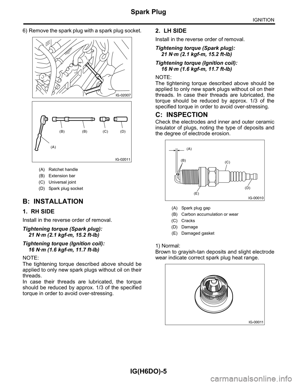
6) Remove the spark plug with a spark plug socket.
B: INSTALLATION
1. RH SIDE
Install in the reverse order of removal.
Tightening torque (Spark plug):
21 N·m (2.1 kgf-m, 15.2 ft-lb)
Tightening torque (Ignition coil):
16 N·m (1.6 kgf-m, 11.7 ft-lb)
NOTE:
The tightening torque described above should be
applied to only new spark plugs without oil on their
threads.
In case their threads are lubricated, the torque
should be reduced by approx. 1/3 of the specified
torque in order to avoid over-stressing.
2. LH SIDE
Install in the reverse order of removal.
Tightening torque (Spark plug):
21 N·m (2.1 kgf-m, 15.2 ft-lb)
Tightening torque (Ignition coil):
16 N·m (1.6 kgf-m, 11.7 ft-lb)
NOTE:
The tightening torque described above should be
applied to only new spark plugs without oil on their
threads. In case their threads are lubricated, the
torque should be reduced by approx. 1/3 of the
specified torque in order to avoid over-stressing.
C: INSPECTION
Check the electrodes and inner and outer ceramic
insulator of plugs, noting the type of deposits and
the degree of electrode erosion.
1) Normal:
Brown to grayish-tan deposits and slight electrode
wear indicate correct spark plug heat range.
(A) Ratchet handle
(B) Extension bar
(C) Universal joint
(D) Spark plug socket
IG-02007
(D)(C)(B)(B)
(A)
IG-02011
(A) Spark plug gap
(B) Carbon accumulation or wear
(C) Cracks
(D) Damage
(E) Damaged gasket
IG-00010
(A)
(B)(C)
(D)
(E)
IG-00011
Page 1842 of 2453
IG(H6DO)-7
Ignition Coil & Ignitor Assembly
IGNITION
3. Ignition Coil & Ignitor Assem-
bly
A: REMOVAL
Direct ignition type has been adopted. Refer to
“Spark Plug” for removal procedure.
IG(H6DO)-4, REMOVAL, Spark Plug.>
B: INSTALLATION
Install in the reverse order of removal.
Tightening torque:
16 N·m (1.6 kgf-m, 11.7 ft-lb)
C: INSPECTION
For inspection procedure, refer to “Diagnostics for
Engine Starting Failure.”
63, IGNITION CONTROL SYSTEM, Diagnostics
for Engine Starting Failure.>
Page 1851 of 2453
LU(H6DO)-2
General Description
LUBRICATION
1. General Description
A: SPECIFICATION
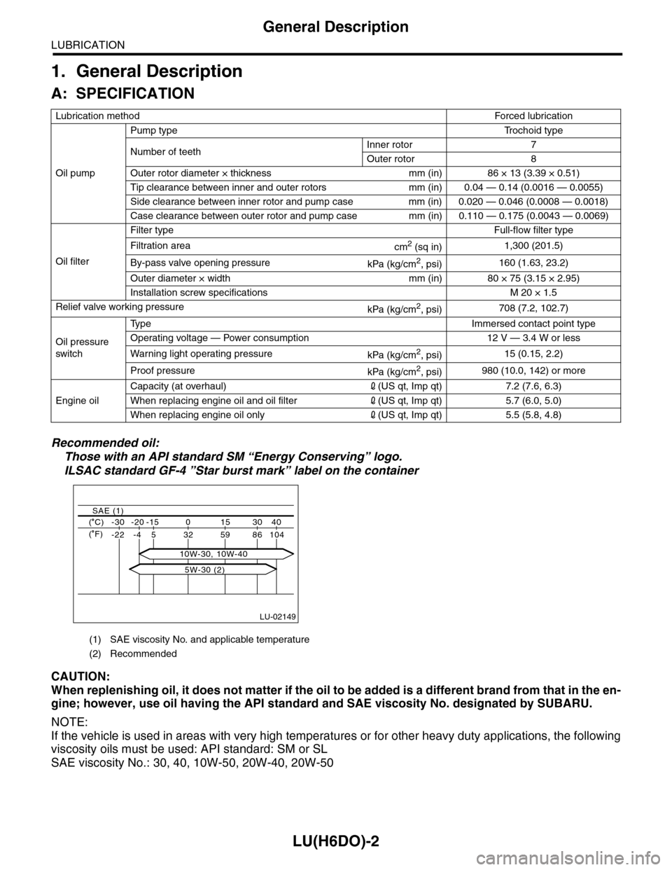
Recommended oil:
Those with an API standard SM “Energy Conserving” logo.
ILSAC standard GF-4 ”Star burst mark” label on the container
CAUTION:
When replenishing oil, it does not matter if the oil to be added is a different brand from that in the en-
gine; however, use oil having the API standard and SAE viscosity No. designated by SUBARU.
NOTE:
If the vehicle is used in areas with very high temperatures or for other heavy duty applications, the following
viscosity oils must be used: API standard: SM or SL
SAE viscosity No.: 30, 40, 10W-50, 20W-40, 20W-50
Lubrication methodForced lubr ication
Oil pump
Pump typeTr o c h o i d t y p e
Number of teethInner rotor 7
Outer rotor 8
Outer rotor diameter × thickness mm (in) 86 × 13 (3.39 × 0.51)
Tip clearance between inner and outer rotors mm (in) 0.04 — 0.14 (0.0016 — 0.0055)
Side clearance between inner rotor and pump case mm (in) 0.020 — 0.046 (0.0008 — 0.0018)
Case clearance between outer rotor and pump case mm (in) 0.110 — 0.175 (0.0043 — 0.0069)
Oil filter
Filter typeFull-flow filter type
Filtration areacm2 (sq in)1,300 (201.5)
By-pass valve opening pressurekPa (kg/cm2, psi)160 (1.63, 23.2)
Outer diameter × width mm (in) 80 × 75 (3.15 × 2.95)
Installation screw specifications M 20 × 1.5
Relief valve working pressurekPa (kg/cm2, psi)708 (7.2, 102.7)
Oil pressure
switch
Ty p eImmersed contact point type
Operating voltage — Power consumption 12 V — 3.4 W or less
Wa r ni n g l ig h t o p era t i ng pr e ss ur ekPa (kg/cm2, psi)15 (0.15, 2.2)
Proof pressurekPa (kg/cm2, psi)980 (10.0, 142) or more
Engine oil
Capacity (at overhaul)2(US qt, Imp qt) 7.2 (7.6, 6.3)
When replacing engine oil and oil filter2(US qt, Imp qt) 5.7 (6.0, 5.0)
When replacing engine oil only2(US qt, Imp qt) 5.5 (5.8, 4.8)
(1) SAE viscosity No. and applicable temperature
(2) Recommended
LU-02149
( C) -30 -20 -15 0 15 30 40
-22 -4 5 32 59 86 104
SAE (1)
( F)
5W-30 (2)
10W-30, 10W-40
Page 1853 of 2453
LU(H6DO)-4
General Description
LUBRICATION
C: CAUTION
•Wear work clothing, including a cap, protective goggles and protective shoes during operation.
•Remove contamination including dirt and corrosion before removal, installation or disassembly.
•Keep the disassembled parts in order and protect them from dust and dirt.
•Before removal, installation or disassembly, be sure to clarify the failure. Avoid unnecessary removal, in-
stallation, disassembly and replacement.
•Be careful not to burn yourself, because each part on the vehicle is hot after running.
•Be sure to tighten fasteners including bolts and nuts to the specified torque.
•Place shop jacks or rigid racks at the specified points.
•Before disconnecting connectors of sensors or units, be sure to disconnect the ground cable from battery.
D: PREPARATION TOOL
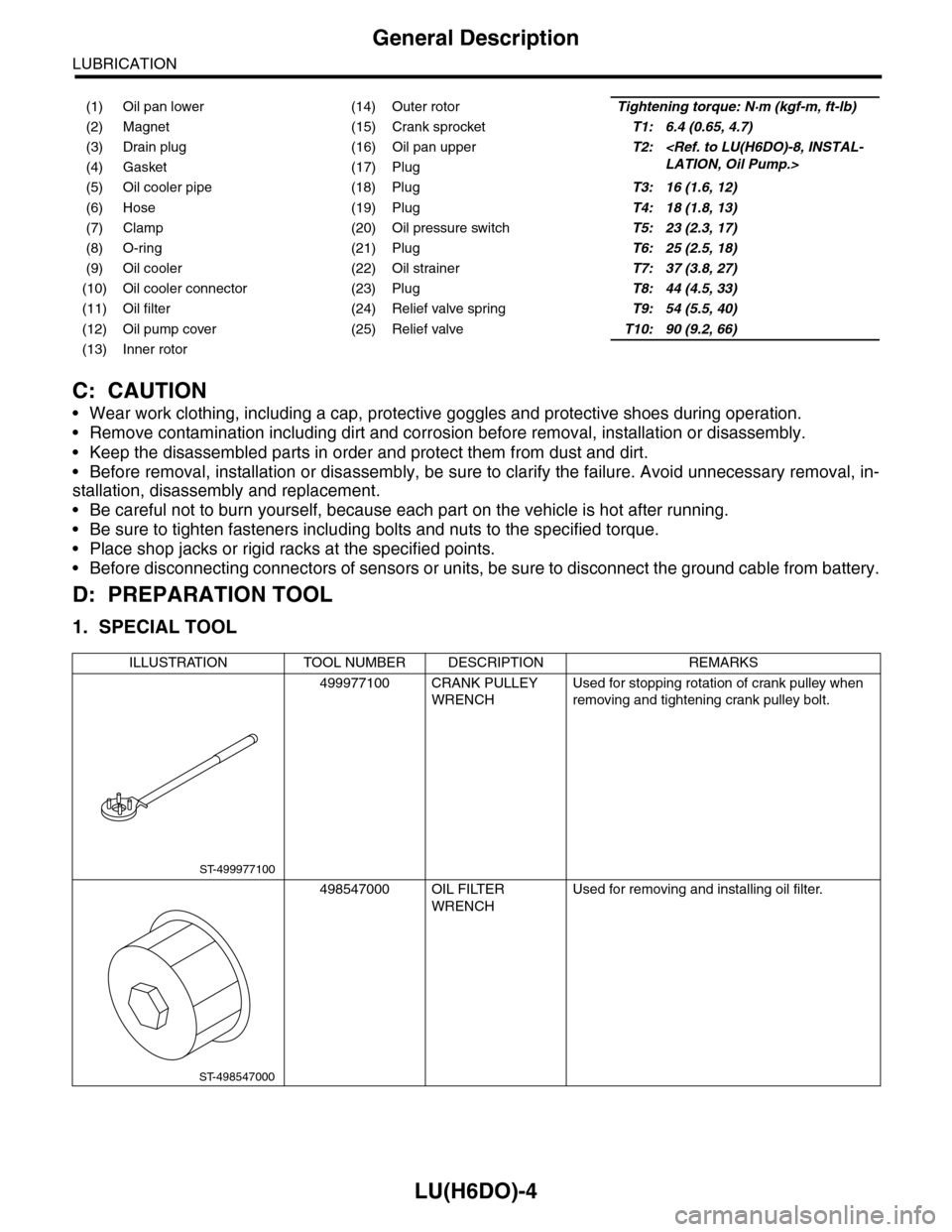
1. SPECIAL TOOL
(1) Oil pan lower (14) Outer rotorTightening torque: N·m (kgf-m, ft-lb)
(2) Magnet (15) Crank sprocketT1: 6.4 (0.65, 4.7)
(3) Drain plug (16) Oil pan upperT2:
LATION, Oil Pump.>(4) Gasket (17) Plug
(5) Oil cooler pipe (18) PlugT3: 16 (1.6, 12)
(6) Hose (19) PlugT4: 18 (1.8, 13)
(7) Clamp (20) Oil pressure switchT5: 23 (2.3, 17)
(8) O-ring (21) PlugT6: 25 (2.5, 18)
(9) Oil cooler (22) Oil strainerT7: 37 (3.8, 27)
(10) Oil cooler connector (23) PlugT8: 44 (4.5, 33)
(11) Oil filter (24) Relief valve springT9: 54 (5.5, 40)
(12) Oil pump cover (25) Relief valveT10: 90 (9.2, 66)
(13) Inner rotor
ILLUSTRATION TOOL NUMBER DESCRIPTION REMARKS
499977100 CRANK PULLEY
WRENCH
Used for stopping rotation of crank pulley when
removing and tightening crank pulley bolt.
498547000 OIL FILTER
WRENCH
Used for removing and installing oil filter.
ST-499977100
ST-498547000
Page 1855 of 2453
LU(H6DO)-6
Oil Pressure System
LUBRICATION
B: INSPECTION
Step Check Yes No
1CHECK COMBINATION METER.
1) Turn the ignition switch ON. (Engine OFF)
2) Check the warning light of combination
meter.
Does the warning light illumi-
nate?
Go to step 2.Repair or replace
the combination
meter.
4, INSPECTION,
Combination
Meter System.>
2CHECK HARNESS CONNECTOR BETWEEN
COMBINATION METER AND OIL PRES-
SURE SWITCH.
1) Turn the ignition switch to OFF.
2) Disconnect the connector from oil pressure
switch.
3) Turn the ignition switch ON.
4) Measure the voltage of harness between oil
pressure switch connector and chassis ground.
Connector & terminal
(E11) No. 1 (+) — Chassis ground (–):
Is the voltage more than 10 V? Replace the oil
pressure switch.
Go to step 3.
3CHECK COMBINATION METER.
1) Turn the ignition switch to OFF.
2) Remove the combination meter.
3) Measure the resistance of combination
meter.
Te r m i n a l s
(i10) No. 4 — (i77) No. 10:
(i10) No. 3 — (i77) No. 10:
Is the resistance less than 10
Ω?
Replace the har-
ness connector
between combina-
tion meter and oil
pressure switch.
Repair or replace
the combination
meter.
4, INSPECTION,
Combination
Meter System.>
Page 1856 of 2453
LU(H6DO)-7
Engine Oil
LUBRICATION
3. Engine Oil
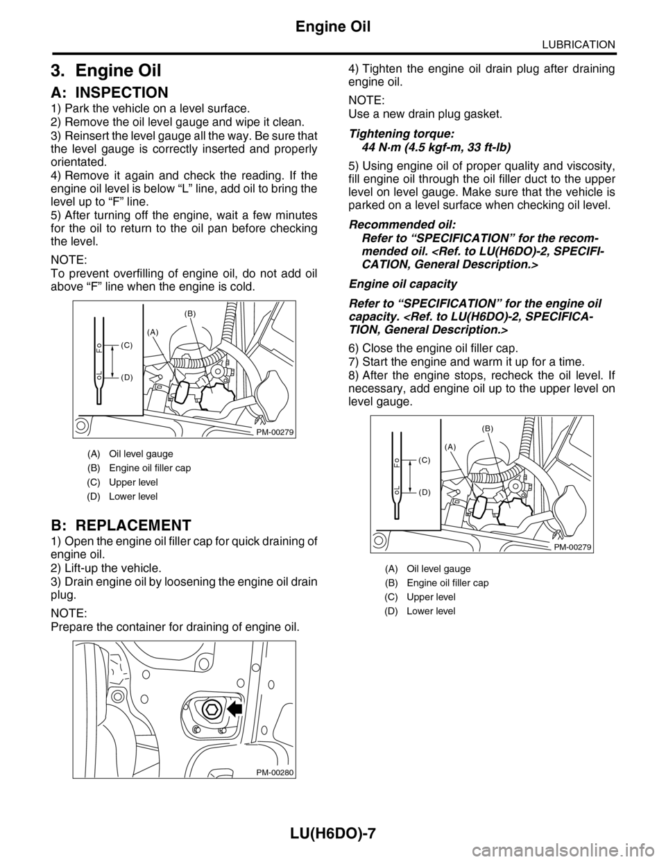
A: INSPECTION
1) Park the vehicle on a level surface.
2) Remove the oil level gauge and wipe it clean.
3) Reinsert the level gauge all the way. Be sure that
the level gauge is correctly inserted and properly
orientated.
4) Remove it again and check the reading. If the
engine oil level is below “L” line, add oil to bring the
level up to “F” line.
5) After turning off the engine, wait a few minutes
for the oil to return to the oil pan before checking
the level.
NOTE:
To prevent overfilling of engine oil, do not add oil
above “F” line when the engine is cold.
B: REPLACEMENT
1) Open the engine oil filler cap for quick draining of
engine oil.
2) Lift-up the vehicle.
3) Drain engine oil by loosening the engine oil drain
plug.
NOTE:
Prepare the container for draining of engine oil.
4) Tighten the engine oil drain plug after draining
engine oil.
NOTE:
Use a new drain plug gasket.
Tightening torque:
44 N·m (4.5 kgf-m, 33 ft-lb)
5) Using engine oil of proper quality and viscosity,
fill engine oil through the oil filler duct to the upper
level on level gauge. Make sure that the vehicle is
parked on a level surface when checking oil level.
Recommended oil:
Refer to “SPECIFICATION” for the recom-
mended oil.
CATION, General Description.>
Engine oil capacity
Refer to “SPECIFICATION” for the engine oil
capacity.
TION, General Description.>
6) Close the engine oil filler cap.
7) Start the engine and warm it up for a time.
8) After the engine stops, recheck the oil level. If
necessary, add engine oil up to the upper level on
level gauge.
(A) Oil level gauge
(B) Engine oil filler cap
(C) Upper level
(D) Lower level
PM-00279
(A)
(B)
(C)
(D)
PM-00280
(A) Oil level gauge
(B) Engine oil filler cap
(C) Upper level
(D) Lower level
PM-00279
(A)
(B)
(C)
(D)
Page 1858 of 2453
LU(H6DO)-9
Oil Pump
LUBRICATION
C: INSPECTION
1. TIP CLEARANCE
Measure the tip clearance of rotors. If the clearance
exceeds specification, replace the rotors as a
matched set.
Tip clearance:
Specification
0.04 — 0.14 mm (0.0016 — 0.0055 in)
2. CASE CLEARANCE
Measure the clearance between the outer rotor and
rear chain cover rotor housing. If the clearance ex-
ceeds the standard value, replace the outer rotor.
Case clearance:
Specification
0.110 — 0.175 mm (0.0043 — 0.0069 in)
3. SIDE CLEARANCE
Measure the clearance between oil pump inner ro-
tor and rear chain cover. If the clearance exceeds
specification, replace the rotors as a matched set.
Side clearance:
Specification
0.020 — 0.046 mm (0.0008 — 0.0018 in)
4. OIL PUMP CASE
Check the worn shaft hole, clogged oil passage,
crank and other parts for faults.
LU-02014
LU-02015
LU-02016