Page 3551 of 3924

DIFFERENTIAL GEAR OILRFD-9
< SERVICE INFORMATION >
CEF
G H
I
J
K L
M A
B
RFD
N
O P
DIFFERENTIAL GEAR OIL
Changing Differential Gear OilINFOID:0000000001327495
DRAINING
1. Stop engine.
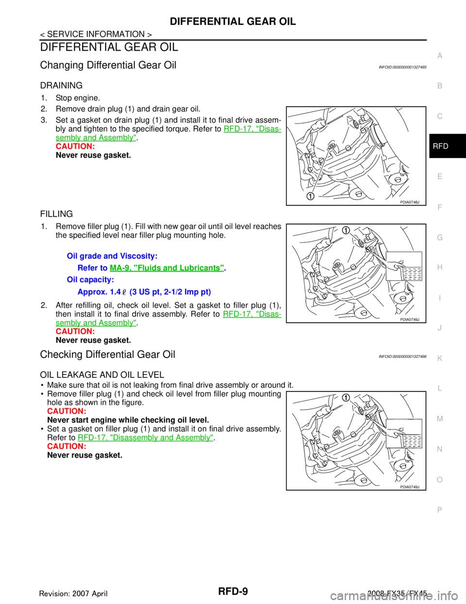
2. Remove drain plug (1) and drain gear oil.
3. Set a gasket on drain plug (1) and install it to final drive assem- bly and tighten to the specified torque. Refer to RFD-17, "
Disas-
sembly and Assembly".
CAUTION:
Never reuse gasket.
FILLING
1. Remove filler plug (1). Fill with new gear oil until oil level reaches the specified level near filler plug mounting hole.
2. After refilling oil, check oil level. Set a gasket to filler plug (1), then install it to final drive assembly. Refer to RFD-17, "
Disas-
sembly and Assembly".
CAUTION:
Never reuse gasket.
Checking Differential Gear OilINFOID:0000000001327496
OIL LEAKAGE AND OIL LEVEL
Make sure that oil is not leaking from final drive assembly or around it.
Remove filler plug (1) and check oil level from filler plug mounting hole as shown in the figure.
CAUTION:
Never start engine while checking oil level.
Set a gasket on filler plug (1) and install it on final drive assembly.
Refer to RFD-17, "
Disassembly and Assembly".
CAUTION:
Never reuse gasket.
PDIA0748J
Oil grade and Viscosity:
Refer to MA-9, "
Fluids and Lubricants".
Oil capacity:
Approx. 1.4 (3 US pt, 2-1/2 Imp pt)
PDIA0749J
PDIA0749J
3AA93ABC3ACD3AC03ACA3AC03AC63AC53A913A773A893A873A873A8E3A773A983AC73AC93AC03AC3
3A893A873A873A8F3A773A9D3AAF3A8A3A8C3A863A9D3AAF3A8B3A8C
Page 3610 of 3924

SC-1
ELECTRICAL
C
DE
F
G H
I
J
L
M
SECTION SC
A
B
SC
N
O P
CONTENTS
STARTING & CHARGING SYSTEM
SERVICE INFORMATION .. ..........................2
PRECAUTIONS .............................................. .....2
Precaution for Supplemental Restraint System
(SRS) "AIR BAG" and "SEAT BELT PRE-TEN-
SIONER" ............................................................. ......
2
PREPARATION ...................................................3
Special Service Tools .......................................... ......3
Commercial Service Tools ........................................3
BATTERY ............................................................4
How to Handle Battery ........................................ ......4
Trouble Diagnosis with Battery Service Center .........6
Removal and Installation ...........................................6
STARTING SYSTEM ...........................................8
System Description ............................................. ......8
Wiring Diagram - START - ........................................9
Trouble Diagnosis with Starting/Charging System
Tester (Starting) ......................................................
10
Removal and Installation (VK45DE Engine Mod-
els) ..........................................................................
13
Removal and Installation [VQ35DE Engine Mod-
els (2WD)] ............................................................ ....
14
Removal and Installation [VQ35DE Engine Mod-
els (AWD)] ...............................................................
15
Disassembly and Assembly .....................................15
Inspection After Disassembly ..................................18
CHARGING SYSTEM .......................................19
System Description ..................................................19
Wiring Diagram - CHARGE - ...................................20
Trouble Diagnosis with Starting/Charging System
Tester (Charging) ....................................................
21
Removal and Installation (VK45DE Engine Mod-
els) ...........................................................................
25
Removal and Installation (VQ35DE Engine Mod-
els) ...........................................................................
27
Disassembly and Assembly .....................................28
SERVICE DATA AND SPECIFICATIONS
(SDS) .................................................................
30
Battery .....................................................................30
Starter ......................................................................30
Alternator .................................................................30
3AA93ABC3ACD3AC03ACA3AC03AC63AC53A913A773A893A873A873A8E3A773A983AC73AC93AC03AC3
3A893A873A873A8F3A773A9D3AAF3A8A3A8C3A863A9D3AAF3A8B3A8C
Page 3612 of 3924
PREPARATIONSC-3
< SERVICE INFORMATION >
C
DE
F
G H
I
J
L
M A
B
SC
N
O P
PREPARATION
Special Service ToolsINFOID:0000000001328241
Commercial Service ToolsINFOID:0000000001328242
Tool number
(Kent-Moore No.)
Tool name Description
—
(J-48087)
Battery Service Center Tests battery.
For operating instructions, refer to Technical
Service Bulletin and Battery Service Center
User Guide.
—
(J-44373 Model MCR620)
Starting/Charging System Tester
Tests starting and charging system.
For operating instructions, refer to Technical
Service Bulletin.
WKIA5280E
SEL403X
Tool number
Tool name Description
Power tool Loosening bolts and nuts
PBIC0190E
3AA93ABC3ACD3AC03ACA3AC03AC63AC53A913A773A893A873A873A8E3A773A983AC73AC93AC03AC3
3A893A873A873A8F3A773A9D3AAF3A8A3A8C3A863A9D3AAF3A8B3A8C
Page 3613 of 3924

SC-4
< SERVICE INFORMATION >
BATTERY
BATTERY
How to Handle BatteryINFOID:0000000001328243
CAUTION:
If it becomes necessary to start the engine with a booster battery and jumper cables, use a 12-volt
booster battery.
After connecting battery cables, ensure that they are tightly clamped to battery terminals for good
contact.
METHODS OF PREVENTING OVER-DISCHARGE
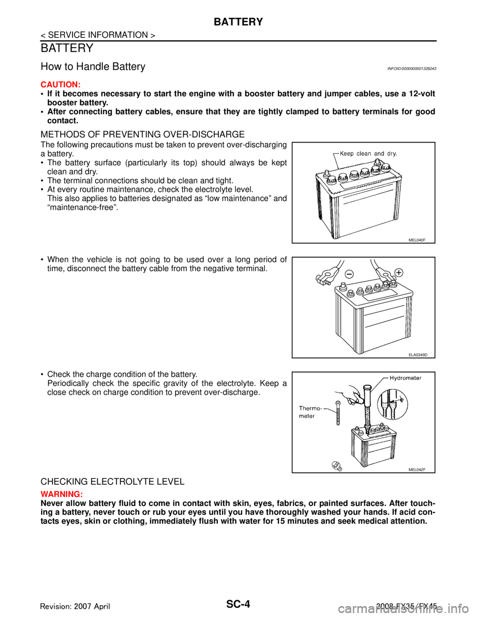
The following precautions must be taken to prevent over-discharging
a battery.
The battery surface (particularly its top) should always be kept clean and dry.
The terminal connections should be clean and tight.
At every routine maintenance, check the electrolyte level.
This also applies to batteries designated as “low maintenance” and
“maintenance-free”.
When the vehicle is not going to be used over a long period of time, disconnect the battery cable from the negative terminal.
Check the charge condition of the battery. Periodically check the specific gr avity of the electrolyte. Keep a
close check on charge condition to prevent over-discharge.
CHECKING ELECTROLYTE LEVEL
WARNING:
Never allow battery fluid to come in contact with skin, eyes, fabrics, or painted surfaces. After touch-
ing a battery, never touch or rub your eyes until you have thoroughly washed your hands. If acid con-
tacts eyes, skin or clothing, immediately flush wit h water for 15 minutes and seek medical attention.
MEL040F
ELA0349D
MEL042F
3AA93ABC3ACD3AC03ACA3AC03AC63AC53A913A773A893A873A873A8E3A773A983AC73AC93AC03AC3
3A893A873A873A8F3A773A9D3AAF3A8A3A8C3A863A9D3AAF3A8B3A8C
Page 3617 of 3924

SC-8
< SERVICE INFORMATION >
STARTING SYSTEM
STARTING SYSTEM
System DescriptionINFOID:0000000001328246
Power is supplied at all times
through 40A fusible link (letter F, located in the fuse and fusible link block)
to ignition switch terminal 1,
through 15A fuse (No. 78, located in the IPDM E/R)
to CPU of IPDM E/R,
through 10A fuse (No. 71, located in the IPDM E/R)
to CPU of IPDM E/R.
When the selector lever in the P or N position, power is supplied
from TCM, and through A/T assembly terminal 9
to IPDM E/R terminal 53.
Ground is supplied
to IPDM E/R terminals 38, 50 and 60
from grounds E21, E50 and E51.
With the ignition switch in the START position, and provided that the IPDM E/R receives a starter relay ON sig-
nal from the CAN lines, the IPDM E/ R is energized and power is supplied
from ignition switch terminal 5
to IPDM E/R terminal 4 and
through IPDM E/R terminal 3
to starter motor terminal 1.
The starter motor plunger closes and provides a clos ed circuit between the battery and starter motor. The
starter motor is grounded to the engine block. With power and ground supplied, cranking occurs and the
engine starts.
3AA93ABC3ACD3AC03ACA3AC03AC63AC53A913A773A893A873A873A8E3A773A983AC73AC93AC03AC3
3A893A873A873A8F3A773A9D3AAF3A8A3A8C3A863A9D3AAF3A8B3A8C
Page 3618 of 3924
STARTING SYSTEMSC-9
< SERVICE INFORMATION >
C
DE
F
G H
I
J
L
M A
B
SC
N
O P
Wiring Diagram - START -INFOID:0000000001328247
VK45DE ENGINE MODELS
TKWM1275E
3AA93ABC3ACD3AC03ACA3AC03AC63AC53A913A773A893A873A873A8E3A773A983AC73AC93AC03AC3
3A893A873A873A8F3A773A9D3AAF3A8A3A8C3A863A9D3AAF3A8B3A8C
Page 3619 of 3924
SC-10
< SERVICE INFORMATION >
STARTING SYSTEM
VQ35DE ENGINE MODELS
Trouble Diagnosis with Starting/Charging System Tester (Starting)INFOID:0000000001328248
For starting system testing, use Starting/Charging Syst em Tester (J-44373). For details and operating instruc-
tions, refer to Technical Service Bulletin.
TKWM1276E
3AA93ABC3ACD3AC03ACA3AC03AC63AC53A913A773A893A873A873A8E3A773A983AC73AC93AC03AC3
3A893A873A873A8F3A773A9D3AAF3A8A3A8C3A863A9D3AAF3A8B3A8C
Page 3620 of 3924
STARTING SYSTEMSC-11
< SERVICE INFORMATION >
C
DE
F
G H
I
J
L
M A
B
SC
N
O P
DIAGNOSTIC PROCEDURE 1
Check “B” Terminal Circuit
CAUTION:
Perform diagnosis under the cond ition that engine cannot start by the following procedure.
*1 For battery testing, use Battery Ser-
vice Center (J-480 87). For details
and operating instructions, refer to
Technical Service Bulletin and/or Bat-
tery Service Center User Guide. *2 Refer to "MINIMUM SPECIFICA-
TION OF CRANKING VOLTAGE
REFERENCING COOLANT TEM-
PERATURE". *3 Refer to "Check “B” Terminal Circuit".
*4 Refer to "Check “S” Connector Cir-
cuit".
SKIB1369E
3AA93ABC3ACD3AC03ACA3AC03AC63AC53A913A773A893A873A873A8E3A773A983AC73AC93AC03AC3
3A893A873A873A8F3A773A9D3AAF3A8A3A8C3A863A9D3AAF3A8B3A8C