2008 INFINITI FX35 no start
[x] Cancel search: no startPage 3308 of 3924
![INFINITI FX35 2008 Service Manual
ENGINE OILLU-23
< SERVICE INFORMATION > [VK45DE]
C
D
E
F
G H
I
J
K L
M A
LU
NP
O
ENGINE OIL
InspectionINFOID:0000000001325829
ENGINE OIL LEVEL
NOTE:
Before starting engine, put vehicle horizontally a INFINITI FX35 2008 Service Manual
ENGINE OILLU-23
< SERVICE INFORMATION > [VK45DE]
C
D
E
F
G H
I
J
K L
M A
LU
NP
O
ENGINE OIL
InspectionINFOID:0000000001325829
ENGINE OIL LEVEL
NOTE:
Before starting engine, put vehicle horizontally a](/manual-img/42/57017/w960_57017-3307.png)
ENGINE OILLU-23
< SERVICE INFORMATION > [VK45DE]
C
D
E
F
G H
I
J
K L
M A
LU
NP
O
ENGINE OIL
InspectionINFOID:0000000001325829
ENGINE OIL LEVEL
NOTE:
Before starting engine, put vehicle horizontally and check
the engine oil level. If engine is already started, stop
it and allow 15 minutes before checking.
1. Pull out oil level gauge and wipe it clean.
2. Insert oil level gauge and make sure the engine oil level is within the range shown in the figure.
3. If it is out of range, adjust it.
ENGINE OIL APPEARANCE
Check engine oil for white turbidity or heavy contamination.
If engine oil becomes turbid and white, it is highl y probable that it is contaminated with engine coolant.
Repair or replace damaged parts.
ENGINE OIL LEAKAGE
Check for oil leakage around the following area.
Oil pan
Oil pan drain plug
Oil pressure switch
Oil filter
Oil cooler
Intake valve timing control cover
Intake valve timing control solenoid valve
Front cover
Chain tensioner cover
Mating surface between cylinder block and cylinder head
Mating surface between cylinder head and rocker cover
Crankshaft oil seals (front and rear)
OIL PRESSURE CHECK
WARNING:
Be careful not to burn yoursel f, as engine oil may be hot.
Oil pressure check should be done in “Parking position”.
1. Check the engine oil level. Refer to "ENGINE OIL LEVEL".
2. Remove front engine undercover with power tool.
3. Disconnect harness connector at oil pressure switch, and remove oil pressure switch using deep socket (commercial ser-
vice tool).
CAUTION:
Do not drop or shock oil pressure switch.
PBIC0801E
PBIC1524E
3AA93ABC3ACD3AC03ACA3AC03AC63AC53A913A773A893A873A873A8E3A773A983AC73AC93AC03AC3
3A893A873A873A8F3A773A9D3AAF3A8A3A8C3A863A9D3AAF3A8B3A8C
Page 3309 of 3924
![INFINITI FX35 2008 Service Manual
LU-24
< SERVICE INFORMATION >[VK45DE]
ENGINE OIL
4. Install oil pressure gauge and hose (SST).
5. Start engine and warm it up to normal operating temperature.
6. Check the engine oil pressure with en INFINITI FX35 2008 Service Manual
LU-24
< SERVICE INFORMATION >[VK45DE]
ENGINE OIL
4. Install oil pressure gauge and hose (SST).
5. Start engine and warm it up to normal operating temperature.
6. Check the engine oil pressure with en](/manual-img/42/57017/w960_57017-3308.png)
LU-24
< SERVICE INFORMATION >[VK45DE]
ENGINE OIL
4. Install oil pressure gauge and hose (SST).
5. Start engine and warm it up to normal operating temperature.
6. Check the engine oil pressure with engine running under no-load.
NOTE:
When engine oil temperature is low, engine oil pressure becomes high.
Engine oil pressure [Eng ine oil temperature at 80°C (176 °F)]
Uni t: kPa (kg/cm2, psi)
If difference is extreme, check oil passage and oil pump for oil leaks.
7. After the inspections, install oil pressure switch as follows:
a. Remove old liquid gasket adhering to oil presser switch and engine.
b. Apply liquid gasket and tighten oil pressure switch to the specification. Use Genuine RTV Silicone Seal ant or equivalent. Refer to GI-44, "
Recommended Chemical Prod-
uct and Sealant".
c. After warming up engine, make sure there is no leakage of engine oil with running engine.
Changing Engine OilINFOID:0000000001325830
WARNING:
Be careful not to burn yoursel f, as engine oil may be hot.
Prolonged and repeated contact with used engine oil may cause ski n cancer. Try to avoid direct skin
contact with used engine oil. If skin contact is made, wash thoroughly with soap or hand cleaner as
soon as possible.
1. Remove front engine undercover with power tool.
2. Warm up engine, put vehicle horizontally and check for engine oil leakage from engine components. Refer
to LU-23, "
Inspection".
3. Stop engine and wait for 15 minutes.
4. Loosen oil filler cap, and then remove drain plug.
5. Drain engine oil.
SLC926
Engine speed Approximate discharge pressure
Idle speed More than 98 (1.0, 14)2,000 rpm More than 294 (3.0, 43)
: 14.8 N·m (1.5 kg-m, 11 ft-lb)
PBIC0993E
3AA93ABC3ACD3AC03ACA3AC03AC63AC53A913A773A893A873A873A8E3A773A983AC73AC93AC03AC3
3A893A873A873A8F3A773A9D3AAF3A8A3A8C3A863A9D3AAF3A8B3A8C
Page 3311 of 3924
![INFINITI FX35 2008 Service Manual
LU-26
< SERVICE INFORMATION >[VK45DE]
OIL FILTER
OIL FILTER
Removal and InstallationINFOID:0000000001325831
REMOVAL
1. Remove front engine undercover with power tool.
2. Using the oil filter wrench ( INFINITI FX35 2008 Service Manual
LU-26
< SERVICE INFORMATION >[VK45DE]
OIL FILTER
OIL FILTER
Removal and InstallationINFOID:0000000001325831
REMOVAL
1. Remove front engine undercover with power tool.
2. Using the oil filter wrench (](/manual-img/42/57017/w960_57017-3310.png)
LU-26
< SERVICE INFORMATION >[VK45DE]
OIL FILTER
OIL FILTER
Removal and InstallationINFOID:0000000001325831
REMOVAL
1. Remove front engine undercover with power tool.
2. Using the oil filter wrench (SST), remove the oil filter.
CAUTION:
Oil filter is provided with relief valve. Use Genuine NissanOil Filter or equivalent.
Be careful not to get burned when engine and engine oil may be hot.
When removing, prepare a sh op cloth to absorb any
engine oil leakage or spillage.
Do not allow engine oil to adhere to drive belts.
Completely wipe off any engine oil that adhere to engine
and vehicle.
INSTALLATION
1. Remove foreign materials adhering to oil filter installation surface.
2. Apply new engine oil to the oil seal circumference of the new oil filter.
3. Screw oil filter manually until it touches the installation surface,
then tighten it by 2/3 turn. Or tighten to specification.
INSPECTION AFTER INSTALLATION
1. Check the engine oil level. Refer to LU-23, "Inspection".
2. Start engine, and check there is no leaks of engine oil.
3. Stop engine and wait for 15 minutes.
4. Check the engine oil level and adjust engine oil. Refer to LU-23, "
Inspection".
PBIC1525E
SMA010
Oil filter:
:17.7 N·m (1.8 kg-m, 13 ft-lb)
SMA229B
3AA93ABC3ACD3AC03ACA3AC03AC63AC53A913A773A893A873A873A8E3A773A983AC73AC93AC03AC3
3A893A873A873A8F3A773A9D3AAF3A8A3A8C3A863A9D3AAF3A8B3A8C
Page 3313 of 3924
![INFINITI FX35 2008 Service Manual
LU-28
< SERVICE INFORMATION >[VK45DE]
OIL COOLER
6. Remove water pipe, as necessary.
INSPECTION AFTER REMOVAL
Oil Cooler
Check oil cooler for cracks. Check oi
l cooler for clogging by blowing through INFINITI FX35 2008 Service Manual
LU-28
< SERVICE INFORMATION >[VK45DE]
OIL COOLER
6. Remove water pipe, as necessary.
INSPECTION AFTER REMOVAL
Oil Cooler
Check oil cooler for cracks. Check oi
l cooler for clogging by blowing through](/manual-img/42/57017/w960_57017-3312.png)
LU-28
< SERVICE INFORMATION >[VK45DE]
OIL COOLER
6. Remove water pipe, as necessary.
INSPECTION AFTER REMOVAL
Oil Cooler
Check oil cooler for cracks. Check oi
l cooler for clogging by blowing through engine coolant inlet. If necessary,
replace oil cooler.
Relief Valve
Check relief valve for movement, cracks and breaks by pushing the ball. If replacement is necessary, remove
relief valve by prying it out with suitable tool. Install a new valve in place by tapping it.
INSTALLATION
Note the following, and install in the reverse order of removal.
Make sure that no foreign objects are adhering to t he installation planes of oil cooler or oil pan.
Tighten connector bolt after aligning stopper on the oil pan side
with protrusion of oil cooler.
INSPECTION AFTER INSTALLATION
1. Make sure level of engine oil and engine coolant, and adjust engine oil and engine coolant. Refer to LU-
23, "Inspection" and CO-37, "Inspection".
2. Start engine, and make sure there is no leak of engine oil or engine coolant.
3. Stop engine and wait for 15 minutes.
4. Check the engine oil level and the engine coolant level again. Refer to LU-23, "
Inspection" and CO-37,
"Inspection".
PBIC1527E
3AA93ABC3ACD3AC03ACA3AC03AC63AC53A913A773A893A873A873A8E3A773A983AC73AC93AC03AC3
3A893A873A873A8F3A773A9D3AAF3A8A3A8C3A863A9D3AAF3A8B3A8C
Page 3315 of 3924
![INFINITI FX35 2008 Service Manual
LU-30
< SERVICE INFORMATION >[VK45DE]
OIL PUMP
a. Insert oil pump drive spacer according to the directions of crank-
shaft key and the two flat surfaces of oil pump inner rotor.
If the positional INFINITI FX35 2008 Service Manual
LU-30
< SERVICE INFORMATION >[VK45DE]
OIL PUMP
a. Insert oil pump drive spacer according to the directions of crank-
shaft key and the two flat surfaces of oil pump inner rotor.
If the positional](/manual-img/42/57017/w960_57017-3314.png)
LU-30
< SERVICE INFORMATION >[VK45DE]
OIL PUMP
a. Insert oil pump drive spacer according to the directions of crank-
shaft key and the two flat surfaces of oil pump inner rotor.
If the positional relationship does not allow the insertion, rotateoil pump inner rotor with a finger to allow spacer.
b. After confirming that the position of each part is in correct condi- tion to allow for spacer, force fit spacer by lightly tapping with
plastic hammer until it contacts and does not go further.
3. Install in the reverse order of removal after this step.
INSPECTION AFTER INSTALLATION
1. Check the engine oil level. refer to LU-23, "Inspection".
2. Start engine, and check there is no leak of engine oil.
3. Stop engine and wait for 15 minutes.
4. Check the engine oil level and adjust engine oil. Refer to LU-23, "
Inspection".
Disassembly and AssemblyINFOID:0000000001325836
DISASSEMBLY
1. Remove oil pump cover.
2. Remove oil pump inner rotor and oil pump outer rotor from oil pump body.
3. After removing regulator valve plug, remove regulator valve spring and regulator valve.
INSPECTION AFTER DISASSEMBLY
Oil Pump Clearance
Measure the clearance with feeler gauge.
- Clearance between oil pump outer rotor and oil pump body (Posi-
tion 1)
- Tip clearance between oil pump inner rotor and oil pump outer rotor (Position 2)
Measure the clearance with feeler gauge and straightedge.
- Side clearance between oil pump inner rotor and oil pump body (Position 3)
- Side clearance between oil pump outer rotor and oil pump body (Position 4)
Calculate the clearance between oil pump inner rotor and oil pump body as follows:
OIL PUMP INNER ROTOR OUTER DIAMETER
PBIC0058E
Standard : 0.114 - 0.200 mm (0.0045 - 0.0079 in)
Standard : Below 0.180 mm (0.0071 in)
PBIC0139E
Standard : 0.030 - 0.070 mm (0.0012 - 0.0028 in)
Standard : 0.030 - 0.090 mm (0.0012 - 0.0035 in)
PBIC0140E
3AA93ABC3ACD3AC03ACA3AC03AC63AC53A913A773A893A873A873A8E3A773A983AC73AC93AC03AC3
3A893A873A873A8F3A773A9D3AAF3A8A3A8C3A863A9D3AAF3A8B3A8C
Page 3334 of 3924

ENGINE MAINTENANCE (VQ35DE ENGINE)MA-17
< SERVICE INFORMATION >
C
DE
F
G H
I
J
K
M A
B
MA
N
O P
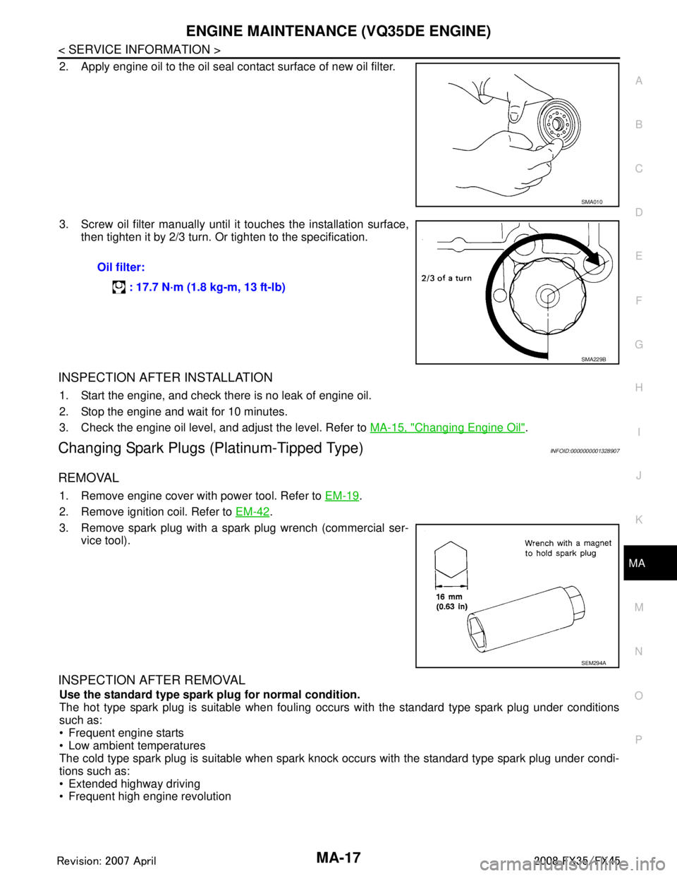
2. Apply engine oil to the oil seal contact surface of new oil filter.
3. Screw oil filter manually until it touches the installation surface,
then tighten it by 2/3 turn. Or tighten to the specification.
INSPECTION AFTER INSTALLATION
1. Start the engine, and check there is no leak of engine oil.
2. Stop the engine and wait for 10 minutes.
3. Check the engine oil level, and adjust the level. Refer to MA-15, "
Changing Engine Oil".
Changing Spark Plugs (Platinum-Tipped Type)INFOID:0000000001328907
REMOVAL
1. Remove engine cover with power tool. Refer to EM-19.
2. Remove ignition coil. Refer to EM-42
.
3. Remove spark plug with a spark plug wrench (commercial ser- vice tool).
INSPECTION AFTER REMOVAL
Use the standard type spark plug for normal condition.
The hot type spark plug is suitable when fouling occurs with the standard type spark plug under conditions
such as:
Frequent engine starts
Low ambient temperatures
The cold type spark plug is suitable when spark knock occurs with the standard type spark plug under condi-
tions such as:
Extended highway driving
Frequent high engine revolution
SMA010
Oil filter:
: 17.7 N·m (1.8 kg-m, 13 ft-lb)
SMA229B
SEM294A
3AA93ABC3ACD3AC03ACA3AC03AC63AC53A913A773A893A873A873A8E3A773A983AC73AC93AC03AC3
3A893A873A873A8F3A773A9D3AAF3A8A3A8C3A863A9D3AAF3A8B3A8C
Page 3341 of 3924

MA-24
< SERVICE INFORMATION >
ENGINE MAINTENANCE (VK45DE ENGINE)
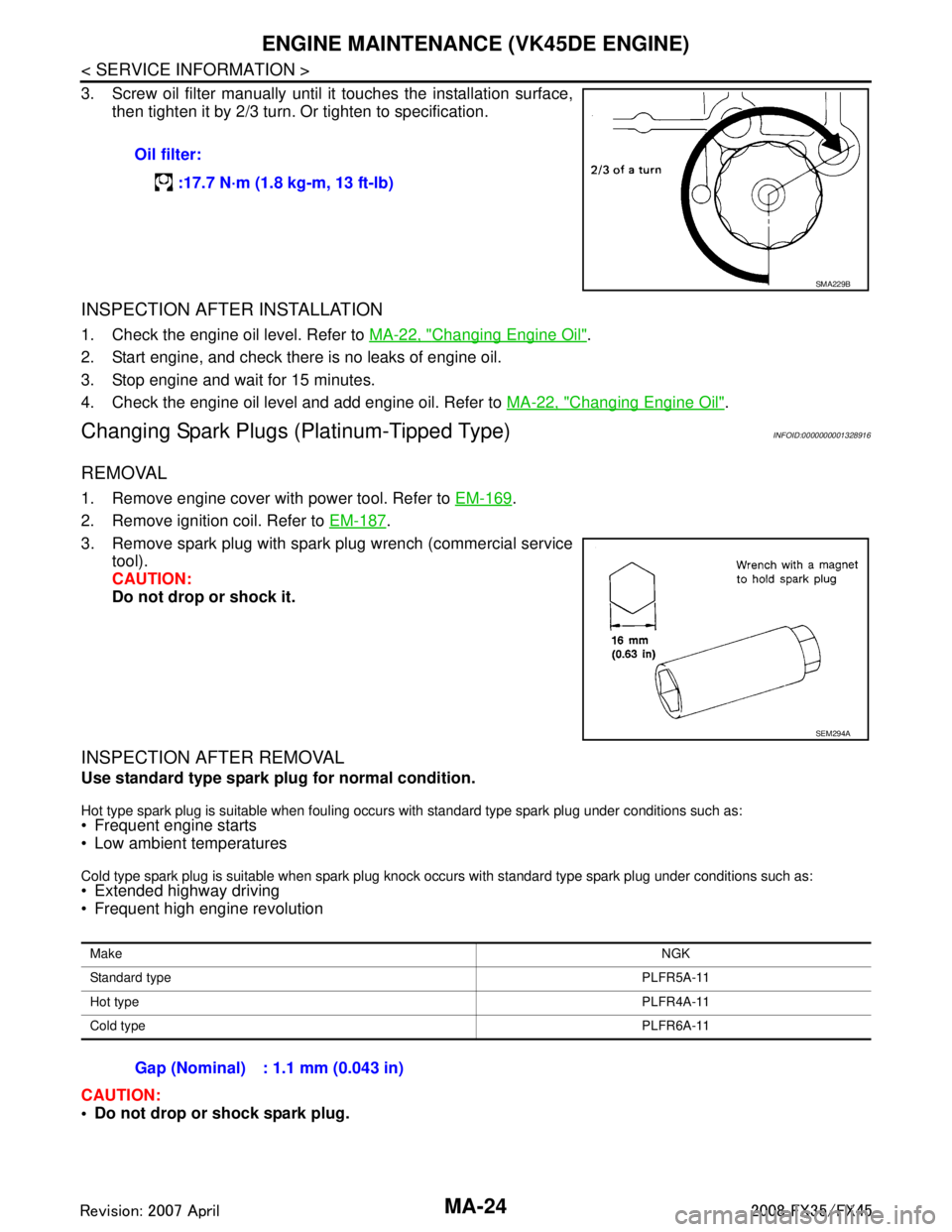
3. Screw oil filter manually until it touches the installation surface,
then tighten it by 2/3 turn. Or tighten to specification.
INSPECTION AFTER INSTALLATION
1. Check the engine oil level. Refer to MA-22, "Changing Engine Oil".
2. Start engine, and check there is no leaks of engine oil.
3. Stop engine and wait for 15 minutes.
4. Check the engine oil level and add engine oil. Refer to MA-22, "
Changing Engine Oil".
Changing Spark Plugs (Platinum-Tipped Type)INFOID:0000000001328916
REMOVAL
1. Remove engine cover with power tool. Refer to EM-169.
2. Remove ignition coil. Refer to EM-187
.
3. Remove spark plug with spark plug wrench (commercial service tool).
CAUTION:
Do not drop or shock it.
INSPECTION AFTER REMOVAL
Use standard type spark plug for normal condition.
Hot type spark plug is suitable when fouling occurs with standard type spark plug under conditions such as: Frequent engine starts
Low ambient temperatures
Cold type spark plug is suitable when spark plug knock occurs with standard type spark plug under conditions such as: Extended highway driving
Frequent high engine revolution
CAUTION:
Do not drop or shock spark plug.Oil filter:
:17.7 N·m (1.8 kg-m, 13 ft-lb)
SMA229B
SEM294A
Make NGK
Standard type PLFR5A-11
Hot type PLFR4A-11
Cold type PLFR6A-11
Gap (Nominal) : 1.1 mm (0.043 in)
3AA93ABC3ACD3AC03ACA3AC03AC63AC53A913A773A893A873A873A8E3A773A983AC73AC93AC03AC3
3A893A873A873A8F3A773A9D3AAF3A8A3A8C3A863A9D3AAF3A8B3A8C
Page 3343 of 3924

MA-26
< SERVICE INFORMATION >
CHASSIS AND BODY MAINTENANCE
CHASSIS AND BODY MAINTENANCE
Checking Exhaust SystemINFOID:0000000001328918
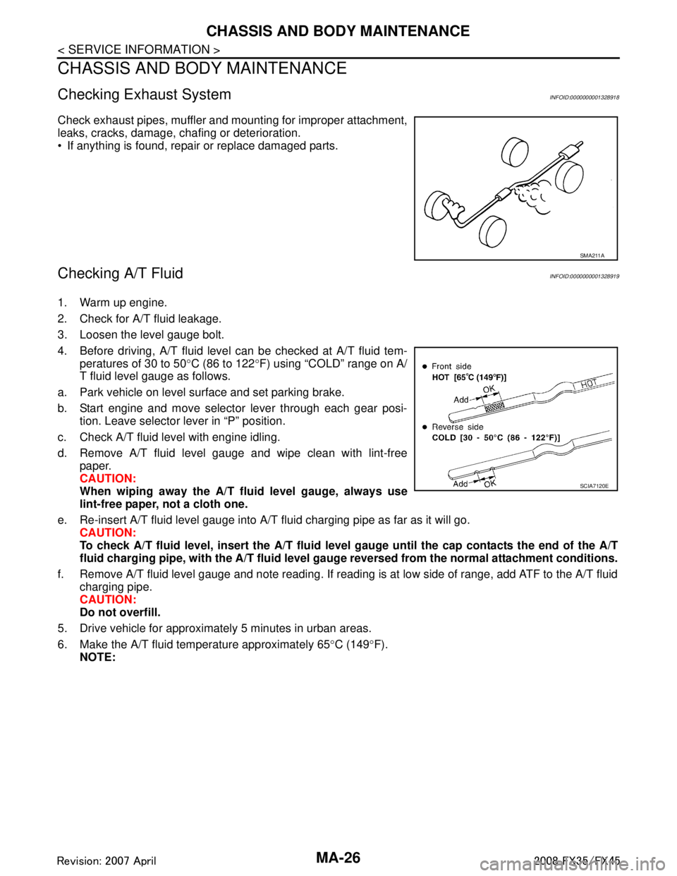
Check exhaust pipes, muffler and mounting for improper attachment,
leaks, cracks, damage, chafing or deterioration.
If anything is found, repair or replace damaged parts.
Checking A/T FluidINFOID:0000000001328919
1. Warm up engine.
2. Check for A/T fluid leakage.
3. Loosen the level gauge bolt.
4. Before driving, A/T fluid level can be checked at A/T fluid tem-
peratures of 30 to 50 °C (86 to 122 °F) using “COLD” range on A/
T fluid level gauge as follows.
a. Park vehicle on level surface and set parking brake.
b. Start engine and move selector lever through each gear posi- tion. Leave selector lever in “P” position.
c. Check A/T fluid level with engine idling.
d. Remove A/T fluid level gauge and wipe clean with lint-free paper.
CAUTION:
When wiping away the A/T flui d level gauge, always use
lint-free paper, not a cloth one.
e. Re-insert A/T fluid level gauge into A/T fluid charging pipe as far as it will go. CAUTION:
To check A/T fluid level, insert the A/T fluid level gauge until the cap contacts the end of the A/T
fluid charging pipe, with the A/ T fluid level gauge reversed from the normal attachment conditions.
f. Remove A/T fluid level gauge and note reading. If reading is at low side of range, add ATF to the A/T fluid
charging pipe.
CAUTION:
Do not overfill.
5. Drive vehicle for approximately 5 minutes in urban areas.
6. Make the A/T fluid temperature approximately 65 °C (149 °F).
NOTE:
SMA211A
SCIA7120E
3AA93ABC3ACD3AC03ACA3AC03AC63AC53A913A773A893A873A873A8E3A773A983AC73AC93AC03AC3
3A893A873A873A8F3A773A9D3AAF3A8A3A8C3A863A9D3AAF3A8B3A8C