2008 INFINITI FX35 no start
[x] Cancel search: no startPage 3007 of 3924

IP-6
< SERVICE INFORMATION >
SQUEAK AND RATTLE TROUBLE DIAGNOSES
Insulates where slight movement is present. Ideal for instrument panel applications.
SILICONE GREASE
Used in of UHMW tape that will be visible or not fit.
Note: Will only last a few months.
SILICONE SPRAY
Use when grease cannot be applied.
DUCT TAPE
Use to eliminate movement.
CONFIRM THE REPAIR
Confirm that the cause of a noise is repaired by test driving the vehicle. Operate the vehicle under the same
conditions as when the noise originally occurred. Refer to the notes on the Diagnostic Worksheet.
Generic Squeak and Rattle TroubleshootingINFOID:0000000001328085
Refer to Table of Contents for specific component removal and installation information.
INSTRUMENT PANEL
Most incidents are caused by contact and movement between:
1. The cluster lid A and instrument panel
2. Acrylic lens and combination meter housing
3. Instrument panel to front pillar garnish
4. Instrument panel to windshield
5. Instrument panel mounting pins
6. Wiring harnesses behind the combination meter
7. A/C defroster duct and duct joint
These incidents can usually be located by tapping or moving the components to duplicate the noise or by
pressing on the components while driving to stop the noi se. Most of these incidents can be repaired by apply-
ing felt cloth tape or silicon spray (in hard to reach areas). Urethane pads can be used to insulate wiring har-
ness.
CAUTION:
Do not use silicone spray to isolate a squeak or ra ttle. If you saturate the area with silicone, you will
not be able to recheck the repair.
CENTER CONSOLE
Components to pay attention to include:
1. Shifter assembly cover to finisher
2. A/C control unit and cluster lid C
3. Wiring harnesses behind audio and A/C control unit
The instrument panel repair and isolation pr ocedures also apply to the center console.
DOORS
Pay attention to the:
1. Finisher and inner panel making a slapping noise
2. Inside handle escutcheon to door finisher
3. Wiring harnesses tapping
4. Door striker out of alignment causing a popping noise on starts and stops
Tapping or moving the components or pressing on them wh ile driving to duplicate the conditions can isolate
many of these incidents. You can usually insulate the areas with felt cloth tape or insulator foam blocks from
the NISSAN Squeak and Rattle Kit (J43980) to repair the noise.
TRUNK
Trunk noises are often caused by a loose jack or loose items put into the trunk by the owner.
In addition look for:
1. Trunk lid dumpers out of adjustment
2. Trunk lid striker out of adjustment
3. The trunk lid torsion bars knocking together
4. A loose license plate or bracket
3AA93ABC3ACD3AC03ACA3AC03AC63AC53A913A773A893A873A873A8E3A773A983AC73AC93AC03AC3
3A893A873A873A8F3A773A9D3AAF3A8A3A8C3A863A9D3AAF3A8B3A8C
Page 3030 of 3924
![INFINITI FX35 2008 Service Manual
LAN-10
< SERVICE INFORMATION >[CAN FUNDAMENTAL]
TROUBLE DIAGNOSIS
Self-Diagnosis
INFOID:0000000001451950
CAN Diagnostic Support MonitorINFOID:0000000001451951
CONSULT-III and CAN diagnostic support m INFINITI FX35 2008 Service Manual
LAN-10
< SERVICE INFORMATION >[CAN FUNDAMENTAL]
TROUBLE DIAGNOSIS
Self-Diagnosis
INFOID:0000000001451950
CAN Diagnostic Support MonitorINFOID:0000000001451951
CONSULT-III and CAN diagnostic support m](/manual-img/42/57017/w960_57017-3029.png)
LAN-10
< SERVICE INFORMATION >[CAN FUNDAMENTAL]
TROUBLE DIAGNOSIS
Self-Diagnosis
INFOID:0000000001451950
CAN Diagnostic Support MonitorINFOID:0000000001451951
CONSULT-III and CAN diagnostic support monitor (on-boar d diagnosis function) are used for detecting root
cause.
MONITOR ITEM (CONSULT-III)
Unit name Symptom
ECM Engine torque limiting is affected, and shift harshness increases.
Engine speed drops.
BCM Reverse warning chime does not sound.
The front wiper moves under continuous operation mode even though the front
wiper switch being in the intermittent position.
The room lamp does not turn ON.
The engine does not start (if an error or malfunction occurs while turning the igni- tion switch OFF.)
The steering lock does not release (if an error or malfunction occurs while turning the ignition switch OFF.)
EPS control unit The steeri ng effort increases.
Combination meter The tachometer and the speedometer do not move.
Warning lamps turn ON.
Indicator lamps do not turn ON.
ABS actuator and electric unit (control unit) Normal operation.
TCM No impact on operation.
IPDM E/R When the ignition switch is ON,
The headlamps (Lo) turn ON.
The cooling fan continues to rotate.
DTC
Self-diagnosis item
(CONSULT-III indication) DTC detection condition Inspection/Action
U1000 CAN COMM CIRCUIT When ECM is not transmitting or receiving CAN
communication signal of OBD (emission-related
diagnosis) for 2 seconds or more.
Refer to LAN-13
.
When a control unit (except for ECM) is not
transmitting or receiving CAN communication
signal for 2 seconds or more.
U1001 CAN COMM CIRCUIT When ECM is not transmitting or receiving CAN
communication signal other than OBD (emis-
sion-related diagnosis) for 2 seconds or more.
U1002 SYSTEM COMM When a control unit is not transmitting or receiv-
ing CAN communication signal for 2 seconds or
less. Start the inspection. Re-
fer to the applicable sec-
tion of the indicated
control unit.
U1010 CONTROL UNIT [CAN] When an error is detected during the initial diag-
nosis for CAN controller of each control unit. Replace the control unit
indicating “U1010”.
3AA93ABC3ACD3AC03ACA3AC03AC63AC53A913A773A893A873A873A8E3A773A983AC73AC93AC03AC3
3A893A873A873A8F3A773A9D3AAF3A8A3A8C3A863A9D3AAF3A8B3A8C
Page 3056 of 3924
![INFINITI FX35 2008 Service Manual
LAN-36
< SERVICE INFORMATION >[CAN]
INDEX FOR DTC
SERVICE INFORMATION
INDEX FOR DTC
DTC No. IndexINFOID:0000000001328627
DTCSelf-diagnosis item
(CONSULT-III indication) DTC detection condition Inspe INFINITI FX35 2008 Service Manual
LAN-36
< SERVICE INFORMATION >[CAN]
INDEX FOR DTC
SERVICE INFORMATION
INDEX FOR DTC
DTC No. IndexINFOID:0000000001328627
DTCSelf-diagnosis item
(CONSULT-III indication) DTC detection condition Inspe](/manual-img/42/57017/w960_57017-3055.png)
LAN-36
< SERVICE INFORMATION >[CAN]
INDEX FOR DTC
SERVICE INFORMATION
INDEX FOR DTC
DTC No. IndexINFOID:0000000001328627
DTCSelf-diagnosis item
(CONSULT-III indication) DTC detection condition Inspection
U1000 CAN COMM CIRCUIT When ECM is not transmitting or receiving CAN
communication signal of OBD (emission-related
diagnosis) for 2 seconds or more.
Refer to LAN-37
.
When a control unit (except for ECM) is not
transmitting or receiving CAN communication
signal for 2 seconds or more.
U1001 CAN COMM CIRCUIT When ECM is not transmitting or receiving CAN
communication signal other than OBD (emis-
sion-related diagnosis) for 2 seconds or more.
U1002 SYSTEM COMM When a control unit is not transmitting or receiv-
ing CAN communication signal for 2 seconds or
less. Start the inspection. Re-
fer to the applicable sec-
tion of the indicated
control unit.
U1010 CONTROL UNIT [CAN] When an error is detected during the initial diag-
nosis for CAN controller of each control unit. Replace the control unit
indicating “U1010”.
3AA93ABC3ACD3AC03ACA3AC03AC63AC53A913A773A893A873A873A8E3A773A983AC73AC93AC03AC3
3A893A873A873A8F3A773A9D3AAF3A8A3A8C3A863A9D3AAF3A8B3A8C
Page 3102 of 3924
![INFINITI FX35 2008 Service Manual
LAN-82
< SERVICE INFORMATION >[CAN]
TROUBLE DIAGNOSIS
Inspection result
Reproduced>>GO TO 6.
Non-reproduced>>Start the diagnosis again. Follow
the trouble diagnosis procedure when past error is
dete INFINITI FX35 2008 Service Manual
LAN-82
< SERVICE INFORMATION >[CAN]
TROUBLE DIAGNOSIS
Inspection result
Reproduced>>GO TO 6.
Non-reproduced>>Start the diagnosis again. Follow
the trouble diagnosis procedure when past error is
dete](/manual-img/42/57017/w960_57017-3101.png)
LAN-82
< SERVICE INFORMATION >[CAN]
TROUBLE DIAGNOSIS
Inspection result
Reproduced>>GO TO 6.
Non-reproduced>>Start the diagnosis again. Follow
the trouble diagnosis procedure when past error is
detected.
6.CHECK UNIT REPRODUCTION
Perform the reproduction test as per the following procedure for each unit.
1. Turn the ignition switch OFF
2. Disconnect the battery cable from the negative terminal.
3. Disconnect one of the unit connecto rs of CAN communication system.
NOTE:
ECM and IPDM E/R have a termination circuit. Check other units first.
4. Connect the battery cable to the negative terminal. Check if the symptoms described in the “Symptom
(Results from interview with customer)” are reproduced.
NOTE:
Although unit-related error symptoms occur, do not confuse them with other symptoms.
Inspection result
Reproduced>>Connect the connector. Check other units as per the above procedure.
Non-reproduced>>Replace unit whose connector was disconnected.
3AA93ABC3ACD3AC03ACA3AC03AC63AC53A913A773A893A873A873A8E3A773A983AC73AC93AC03AC3
3A893A873A873A8F3A773A9D3AAF3A8A3A8C3A863A9D3AAF3A8B3A8C
Page 3107 of 3924

HEADLAMP - XENON TYPE -LT-5
< SERVICE INFORMATION >
C
DE
F
G H
I
J
L
M A
B
LT
N
O P
HEADLAMP - XENON TYPE -
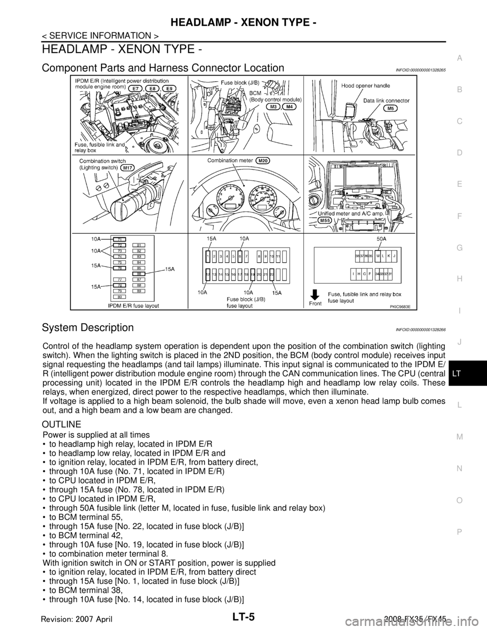
Component Parts and Har ness Connector LocationINFOID:0000000001328265
System DescriptionINFOID:0000000001328266
Control of the headlamp system operation is dependent upon t he position of the combination switch (lighting
switch). When the lighting switch is placed in the 2ND position, the BCM (body control module) receives input
signal requesting the headlamps (and tail lamps) illuminate. This input signal is communicated to the IPDM E/
R (intelligent power distribution module engine room) through the CAN communication lines. The CPU (central
processing unit) located in the IPDM E/R contro ls the headlamp high and headlamp low relay coils. These
relays, when energized, direct power to the respective headlamps, which then illuminate.
If voltage is applied to a high beam solenoid, the bulb shade will move, even a xenon head lamp bulb comes
out, and a high beam and a low beam are changed.
OUTLINE
Power is supplied at all times
to headlamp high relay, located in IPDM E/R
to headlamp low relay, located in IPDM E/R and
to ignition relay, located in IPDM E/R, from battery direct,
through 10A fuse (No. 71, located in IPDM E/R)
to CPU located in IPDM E/R,
through 15A fuse (No. 78, located in IPDM E/R)
to CPU located in IPDM E/R,
through 50A fusible link (letter M, located in fuse, fusible link and relay box)
to BCM terminal 55,
through 15A fuse [No. 22, located in fuse block (J/B)]
to BCM terminal 42,
through 10A fuse [No. 19, located in fuse block (J/B)]
to combination meter terminal 8.
With ignition switch in ON or START position, power is supplied
to ignition relay, located in IPDM E/R, from battery direct
through 15A fuse [No. 1, located in fuse block (J/B)]
to BCM terminal 38,
through 10A fuse [No. 14, located in fuse block (J/B)]
PKIC9683E
3AA93ABC3ACD3AC03ACA3AC03AC63AC53A913A773A893A873A873A8E3A773A983AC73AC93AC03AC3
3A893A873A873A8F3A773A9D3AAF3A8A3A8C3A863A9D3AAF3A8B3A8C
Page 3117 of 3924

HEADLAMP - XENON TYPE -LT-15
< SERVICE INFORMATION >
C
DE
F
G H
I
J
L
M A
B
LT
N
O P
2. Understand operation description and function description. Refer to LT- 5 , "System Description".
3. Perform Preliminary Check. Refer to LT-15, "
Preliminary Check".
4. Check symptom and repair or replace the cause of malfunction.
5. Does headlamp operate normally? If YES, GO TO 6. If NO, GO TO 4.
6. INSPECTION END
Preliminary CheckINFOID:0000000001328274
CHECK POWER SUPPLY AND GROUND CIRCUIT
1.CHECK FUSES
Check for blown fuses.
Refer to LT- 9 , "
Wiring Diagram - H/LAMP -".
OK or NG
OK >> GO TO 2.
NG >> If fuse is blown, be sure to eliminate caus e of malfunction before installing new fuse. Refer to PG-
3.
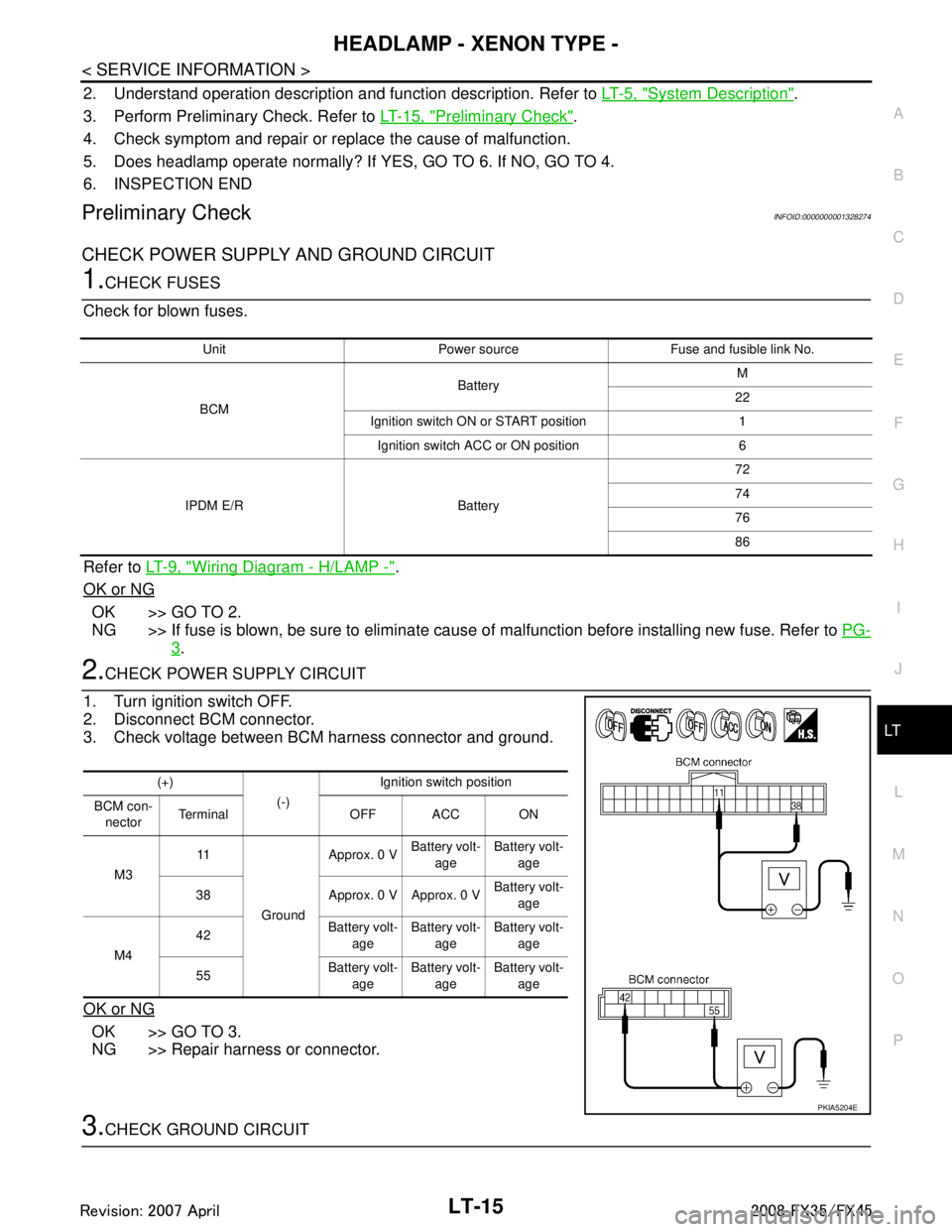
2.CHECK POWER SUPPLY CIRCUIT
1. Turn ignition switch OFF.
2. Disconnect BCM connector.
3. Check voltage between BCM harness connector and ground.
OK or NG
OK >> GO TO 3.
NG >> Repair harness or connector.
3.CHECK GROUND CIRCUIT
Unit Power source Fuse and fusible link No.
BCM Battery
M
22
Ignition switch ON or START position 1 Ignition switch ACC or ON position 6
IPDM E/R Battery 72
74
76
86
(+)
(-)Ignition switch position
BCM con- nector Terminal OFF ACC ON
M3 11
Ground Approx. 0 V
Battery volt-
age Battery volt-
age
38 Approx. 0 V Approx. 0 V Battery volt-
age
M4 42
Battery volt-
age Battery volt-
age Battery volt-
age
55 Battery volt-
age Battery volt-
age Battery volt-
age
PKIA5204E
3AA93ABC3ACD3AC03ACA3AC03AC63AC53A913A773A893A873A873A8E3A773A983AC73AC93AC03AC3
3A893A873A873A8F3A773A9D3AAF3A8A3A8C3A863A9D3AAF3A8B3A8C
Page 3120 of 3924

LT-18
< SERVICE INFORMATION >
HEADLAMP - XENON TYPE -
NOTE:
Perform monitoring of IPDM E/R data with ignition switch ON. When ignition switch is at ACC, display may not
be correct.
ACTIVE TEST
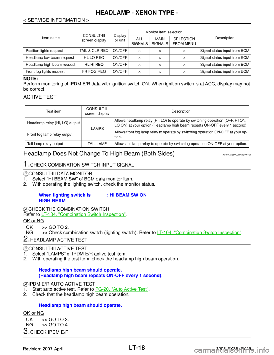
Headlamp Does Not Change To High Beam (Both Sides)INFOID:0000000001381742
1.CHECK COMBINATION SWITCH INPUT SIGNAL
CONSULT-III DATA MONITOR
1. Select “HI BEAM SW” of BCM data monitor item.
2. With operating the lighting switch, check the monitor status.
CHECK THE COMBINATION SWITCH
Refer to LT-104, "
Combination Switch Inspection".
OK or NG
OK >> GO TO 2.
NG >> Check combination switch (lighting switch). Refer to LT-104, "
Combination Switch Inspection".
2.HEADLAMP ACTIVE TEST
CONSULT-III ACTIVE TEST
1. Select “LAMPS” of IPDM E/R active test item.
2. With operating the test item, check the headlamp high beam operation.
IPDM E/R AUTO ACTIVE TEST
1. Start auto active test. Refer to PG-20, "
Auto Active Test".
2. Check that the headlamp high beam operation.
OK or NG
OK >> GO TO 3.
NG >> GO TO 4.
3.CHECK IPDM E/R
Item name CONSULT-III
screen display Display
or unit Monitor item selection
Description
ALL
SIGNALS MAIN
SIGNALS SELECTION
FROM MENU
Position lights request TAIL & CLR REQ ON/OFF ×× ×Signal status input from BCM
Headlamp low beam request HL LO REQ ON/OFF ×× ×Signal status input from BCM
Headlamp high beam request HL HI REQ ON/OFF ×× ×Signal status input from BCM
Front fog lights request FR FOG REQ ON/OFF ×× ×Signal status input from BCM
Te s t i t e mCONSULT-III
screen display Description
Headlamp relay (HI, LO) output
LAMPSAllows headlamp relay (HI, LO) to operate by switching operation (OFF, HI ON,
LO ON) at your option (Headlamp high beam repeats ON-OFF every 1 second).
Front fog lamp relay output Allows front fog lamp relay to operate by switching operation ON-OFF at your op-
tion.
Tail lamp relay output TAIL LAMP Allows tail lamp relay to operate by switching operation ON-OFF at your option.
When lighting switch is
HIGH BEAM : HI BEAM SW ON
Headlamp high beam should operate.
(Headlamp high beam repeats ON-OFF every 1 second).
Headlamp high beam should operate.
3AA93ABC3ACD3AC03ACA3AC03AC63AC53A913A773A893A873A873A8E3A773A983AC73AC93AC03AC3
3A893A873A873A8F3A773A9D3AAF3A8A3A8C3A863A9D3AAF3A8B3A8C
Page 3121 of 3924

HEADLAMP - XENON TYPE -LT-19
< SERVICE INFORMATION >
C
DE
F
G H
I
J
L
M A
B
LT
N
O P
CONSULT-III DATA MONITOR
1. Select “HL LO REQ” and “HL HI RE Q” of IPDM E/R data monitor item.
2. With operating the lighting switch, check the monitor status
OK or NG
OK >> Replace IPDM E/R. Refer to PG-24, "Removal and Installation of IPDM E/R".
NG >> Replace BCM. Refer to BCS-13, "
Removal and Installation of BCM".
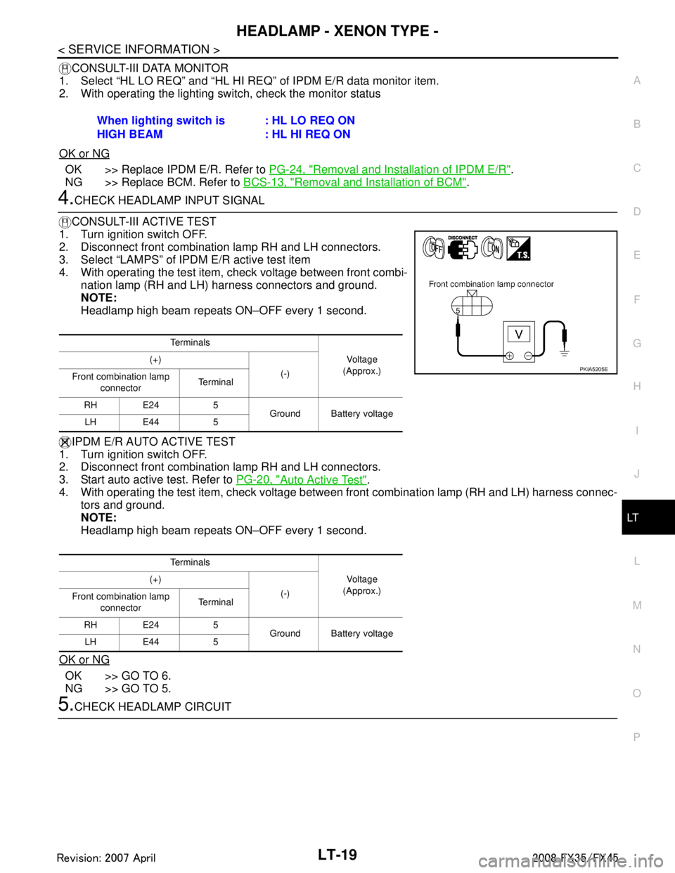
4.CHECK HEADLAMP INPUT SIGNAL
CONSULT-III ACTIVE TEST
1. Turn ignition switch OFF.
2. Disconnect front combination lamp RH and LH connectors.
3. Select “LAMPS” of IPDM E/R active test item
4. With operating the test item, check voltage between front combi- nation lamp (RH and LH) harness connectors and ground.
NOTE:
Headlamp high beam repeats ON–OFF every 1 second.
IPDM E/R AUTO ACTIVE TEST
1. Turn ignition switch OFF.
2. Disconnect front combination lamp RH and LH connectors.
3. Start auto active test. Refer to PG-20, "
Auto Active Test".
4. With operating the test item, check voltage betw een front combination lamp (RH and LH) harness connec-
tors and ground.
NOTE:
Headlamp high beam repeats ON–OFF every 1 second.
OK or NG
OK >> GO TO 6.
NG >> GO TO 5.
5.CHECK HEADLAMP CIRCUIT When lighting switch is
HIGH BEAM
: HL LO REQ ON
: HL HI REQ ON
Te r m i n a l s
Voltag e
(Approx.)
(+)
(-)
Front combination lamp
connector Te r m i n a l
RH E24 5 Ground Battery voltage
LH E44 5
Te r m i n a l s Voltag e
(Approx.)
(+)
(-)
Front combination lamp
connector Te r m i n a l
RH E24 5 Ground Battery voltage
LH E44 5
PKIA5205E
3AA93ABC3ACD3AC03ACA3AC03AC63AC53A913A773A893A873A873A8E3A773A983AC73AC93AC03AC3
3A893A873A873A8F3A773A9D3AAF3A8A3A8C3A863A9D3AAF3A8B3A8C