2008 INFINITI FX35 no start
[x] Cancel search: no startPage 3173 of 3924
FRONT FOG LAMPLT-71
< SERVICE INFORMATION >
C
DE
F
G H
I
J
L
M A
B
LT
N
O P
How to Proceed with Trouble DiagnosisINFOID:0000000001328334
1. Confirm the symptom or customer complaint.
2. Understand operation description and function description. Refer to LT-66, "
System Description".
3. Perform Preliminary Check. Refer to LT-71, "
Preliminary Check".
4. Check symptom and repair or replace the cause of malfunction.
5. Does front fog lamp operate normally? If YES, GO TO 6. If NO, GO TO 4.
6. INSPECTION END
Preliminary CheckINFOID:0000000001328335
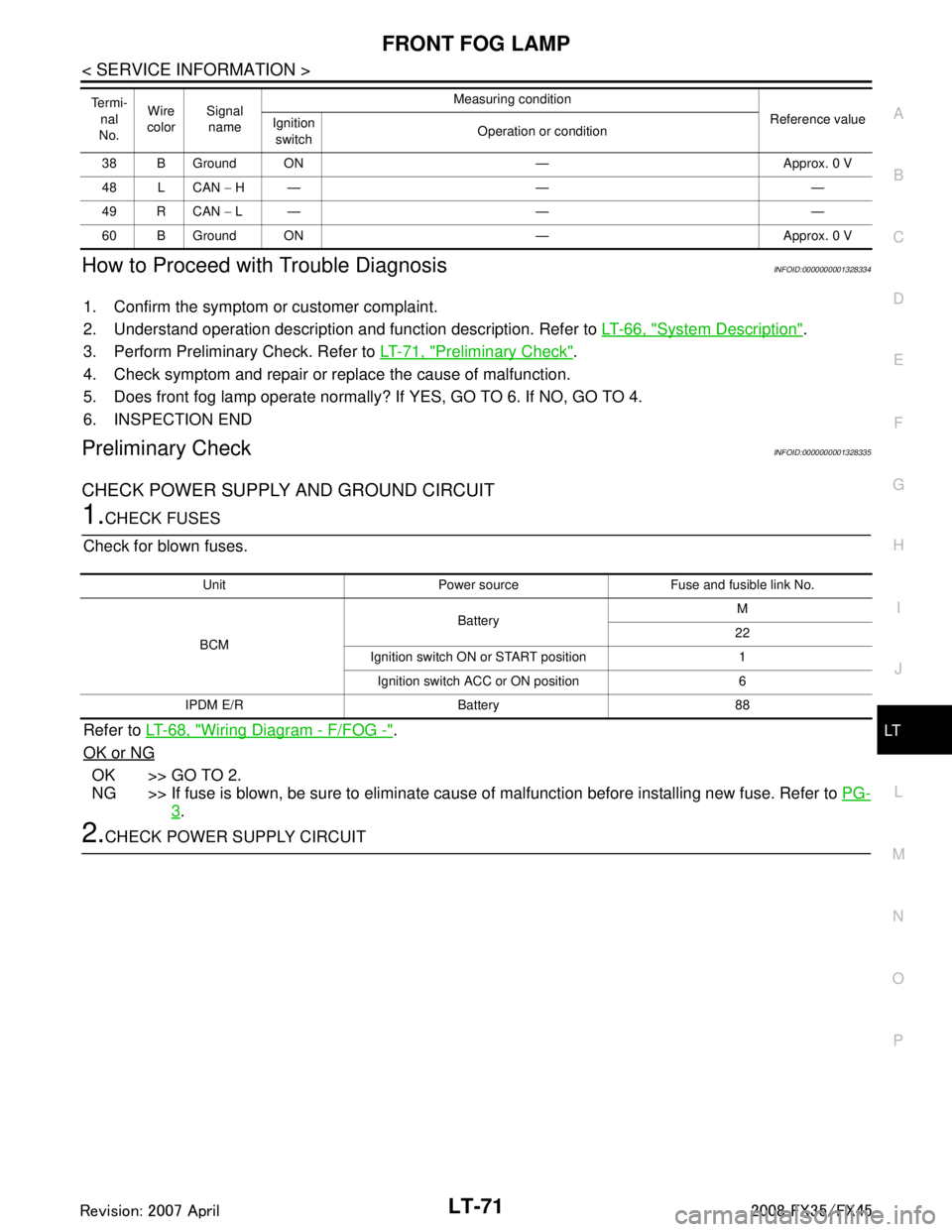
CHECK POWER SUPPLY AND GROUND CIRCUIT
1.CHECK FUSES
Check for blown fuses.
Refer to LT-68, "
Wiring Diagram - F/FOG -".
OK or NG
OK >> GO TO 2.
NG >> If fuse is blown, be sure to eliminate caus e of malfunction before installing new fuse. Refer to PG-
3.
2.CHECK POWER SUPPLY CIRCUIT
38 B Ground ON — Approx. 0 V
48 L CAN − H— — —
49 R CAN − L— — —
60 B Ground ON — Approx. 0 V
Te r m i -
nal
No. Wire
color Signal
name Measuring condition
Reference value
Ignition
switch Operation or condition
Unit Power source Fuse and fusible link No.
BCM Battery
M
22
Ignition switch ON or START position 1 Ignition switch ACC or ON position 6
IPDM E/R Battery 88
3AA93ABC3ACD3AC03ACA3AC03AC63AC53A913A773A893A873A873A8E3A773A983AC73AC93AC03AC3
3A893A873A873A8F3A773A9D3AAF3A8A3A8C3A863A9D3AAF3A8B3A8C
Page 3175 of 3924
FRONT FOG LAMPLT-73
< SERVICE INFORMATION >
C
DE
F
G H
I
J
L
M A
B
LT
N
O P
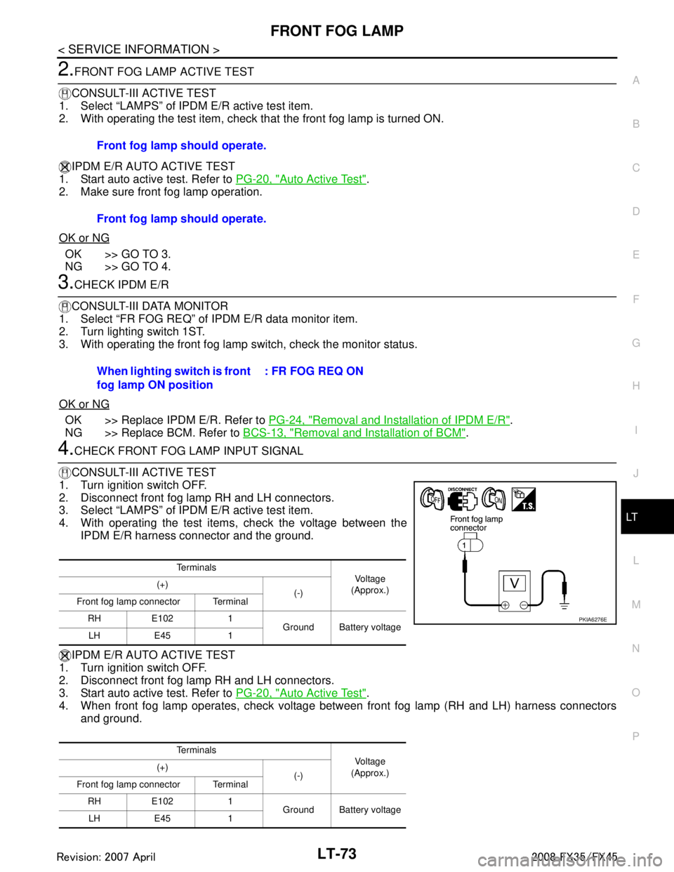
2.FRONT FOG LAMP ACTIVE TEST
CONSULT-III ACTIVE TEST
1. Select “LAMPS” of IPDM E/R active test item.
2. With operating the test item, check th at the front fog lamp is turned ON.
IPDM E/R AUTO ACTIVE TEST
1. Start auto active test. Refer to PG-20, "
Auto Active Test".
2. Make sure front fog lamp operation.
OK or NG
OK >> GO TO 3.
NG >> GO TO 4.
3.CHECK IPDM E/R
CONSULT-III DATA MONITOR
1. Select “FR FOG REQ” of IPDM E/R data monitor item.
2. Turn lighting switch 1ST.
3. With operating the front fog lamp switch, check the monitor status.
OK or NG
OK >> Replace IPDM E/R. Refer to PG-24, "Removal and Installation of IPDM E/R".
NG >> Replace BCM. Refer to BCS-13, "
Removal and Installation of BCM".
4.CHECK FRONT FOG LAMP INPUT SIGNAL
CONSULT-III ACTIVE TEST
1. Turn ignition switch OFF.
2. Disconnect front fog lamp RH and LH connectors.
3. Select “LAMPS” of IPDM E/R active test item.
4. With operating the test items, check the voltage between the IPDM E/R harness connector and the ground.
IPDM E/R AUTO ACTIVE TEST
1. Turn ignition switch OFF.
2. Disconnect front fog lamp RH and LH connectors.
3. Start auto active test. Refer to PG-20, "
Auto Active Test".
4. When front fog lamp operates, check voltage bet ween front fog lamp (RH and LH) harness connectors
and ground. Front fog lamp should operate.
Front fog lamp should operate.
When lighting switch is front
fog lamp ON position
: FR FOG REQ ON
Te r m i n a l s
Vol tag e
(Approx.)
(+)
(-)
Front fog lamp connector Terminal
RH E102 1 Ground Battery voltage
LH E45 1
Te r m i n a l s Vol tag e
(Approx.)
(+)
(-)
Front fog lamp connector Terminal
RH E102 1 Ground Battery voltage
LH E45 1
PKIA6276E
3AA93ABC3ACD3AC03ACA3AC03AC63AC53A913A773A893A873A873A8E3A773A983AC73AC93AC03AC3
3A893A873A873A8F3A773A9D3AAF3A8A3A8C3A863A9D3AAF3A8B3A8C
Page 3180 of 3924
LT-78
< SERVICE INFORMATION >
TURN SIGNAL AND HAZARD WARNING LAMPS
TURN SIGNAL AND HAZARD WARNING LAMPS
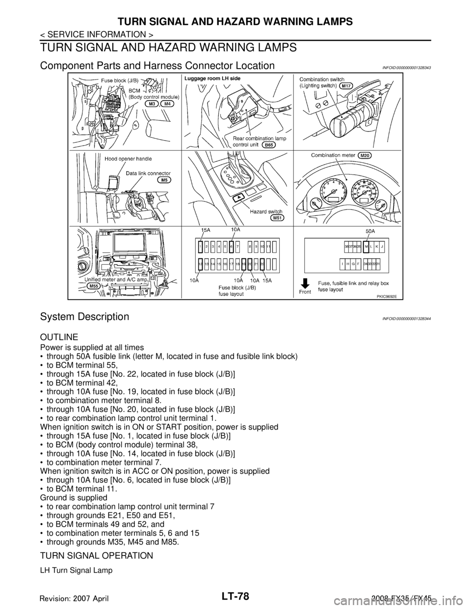
Component Parts and Harn ess Connector LocationINFOID:0000000001328343
System DescriptionINFOID:0000000001328344
OUTLINE
Power is supplied at all times
through 50A fusible link (letter M, located in fuse and fusible link block)
to BCM terminal 55,
through 15A fuse [No. 22, located in fuse block (J/B)]
to BCM terminal 42,
through 10A fuse [No. 19, located in fuse block (J/B)]
to combination meter terminal 8.
through 10A fuse [No. 20, located in fuse block (J/B)]
to rear combination lamp control unit terminal 1.
When ignition switch is in ON or START position, power is supplied
through 15A fuse [No. 1, located in fuse block (J/B)]
to BCM (body control module) terminal 38,
through 10A fuse [No. 14, located in fuse block (J/B)]
to combination meter terminal 7.
When ignition switch is in ACC or ON position, power is supplied
through 10A fuse [No. 6, located in fuse block (J/B)]
to BCM terminal 11.
Ground is supplied
to rear combination lamp control unit terminal 7
through grounds E21, E50 and E51,
to BCM terminals 49 and 52, and
to combination meter terminals 5, 6 and 15
through grounds M35, M45 and M85.
TURN SIGNAL OPERATION
LH Turn Signal Lamp
PKIC9692E
3AA93ABC3ACD3AC03ACA3AC03AC63AC53A913A773A893A873A873A8E3A773A983AC73AC93AC03AC3
3A893A873A873A8F3A773A9D3AAF3A8A3A8C3A863A9D3AAF3A8B3A8C
Page 3190 of 3924
LT-88
< SERVICE INFORMATION >
TURN SIGNAL AND HAZARD WARNING LAMPS
How to Proceed with Trouble Diagnosis
INFOID:0000000001328351
1. Confirm the symptom or customer complaint.
2. Understand operation description and function description. Refer to LT-78, "
System Description".
3. Perform preliminary check. Refer to LT-88, "
Preliminary Check".
4. Check symptom and repair or r eplace the cause of malfunction.
5. Do turn signal and hazard warning lamps operate no rmally? If YES, GO TO 6. If NO, GO TO 4.
6. INSPECTION END
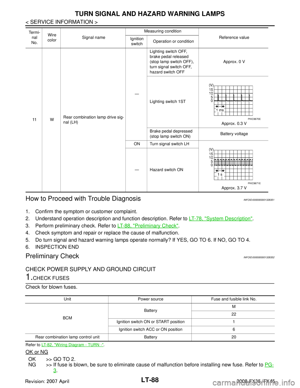
Preliminary CheckINFOID:0000000001328352
CHECK POWER SUPPLY AND GROUND CIRCUIT
1.CHECK FUSES
Check for blown fuses.
Refer to LT- 8 2 , "Wiring Diagram - TURN -".
OK or NG
OK >> GO TO 2.
NG >> If fuse is blown, be sure to eliminate caus e of malfunction before installing new fuse. Refer to PG-
3.
11 WRear combination lamp drive sig-
nal (LH) —Lighting switch OFF,
brake pedal released
(stop lamp switch OFF),
turn signal switch OFF,
hazard switch OFF
Approx. 0 V
Lighting switch 1ST Approx. 0.3 V
Brake pedal depressed
(stop lamp switch ON) Battery voltage
ON Turn signal switch LH
Approx. 3.7 V
— Hazard switch ON
Te r m i -
nal
No. Wire
color Signal name Measuring condition
Reference value
Ignition
switch Operation or conditionPKIC9670E
PKIC9671E
Unit Power source Fuse and fusible link No.
BCM Battery
M
22
Ignition switch ON or START position 1 Ignition switch ACC or ON position 6
Rear combination lamp control unit Battery 20
3AA93ABC3ACD3AC03ACA3AC03AC63AC53A913A773A893A873A873A8E3A773A983AC73AC93AC03AC3
3A893A873A873A8F3A773A9D3AAF3A8A3A8C3A863A9D3AAF3A8B3A8C
Page 3221 of 3924
![INFINITI FX35 2008 Service Manual
PARKING, LICENSE PLATE AND TAIL LAMPS
LT-119
< SERVICE INFORMATION >
C
D E
F
G H
I
J
L
M A
B
LT
N
O P
to BCM terminal 55,
through 15A fuse [No. 22, located in fuse block (J/B)]
to BCM terminal INFINITI FX35 2008 Service Manual
PARKING, LICENSE PLATE AND TAIL LAMPS
LT-119
< SERVICE INFORMATION >
C
D E
F
G H
I
J
L
M A
B
LT
N
O P
to BCM terminal 55,
through 15A fuse [No. 22, located in fuse block (J/B)]
to BCM terminal](/manual-img/42/57017/w960_57017-3220.png)
PARKING, LICENSE PLATE AND TAIL LAMPS
LT-119
< SERVICE INFORMATION >
C
D E
F
G H
I
J
L
M A
B
LT
N
O P
to BCM terminal 55,
through 15A fuse [No. 22, located in fuse block (J/B)]
to BCM terminal 42,
through 10A fuse [No. 20, located in fuse block (J/B)]
to rear combination lamp control unit terminal 1,
through 10A fuse [No. 19, located in fuse block (J/B)]
to combination meter terminal 8 and
to unified meter and A/C amp. terminal 21.
With the ignition switch in ON or START position, power is supplied
through ignition relay, located in IPDM E/R, from battery direct,
through 15A fuse [No. 1, located in fuse block (J/B)]
to BCM terminal 38,
through 10A fuse [No. 14, located in fuse block (J/B)]
to combination meter terminal 7 and
through 10A fuse [No. 12, located in fuse block (J/B)]
to unified meter and A/C amp. terminal 22.
With ignition switch in ACC or ON position, power is supplied
through 10A fuse [No. 6, located in fuse block (J/B)]
to BCM terminal 11.
Ground is supplied
to rear combination lamp control unit terminal 7 and
to IPDM E/R terminals 38 and 60
through grounds E21, E50 and E51,
to BCM terminals 49 and 52
to combination meter terminals 5, 6 and 15, and
to unified meter and A/C amp. terminals 29 and 30
through grounds M35, M45 and M85.
OPERATION BY LIGHTING SWITCH
With the lighting switch in the 1ST or 2ND position (or if the auto light system is activated), the BCM receives
input signal requesting the parking, license plate, side ma rker and tail lamps to illuminate. This input signal is
communicated to the IPDM E/R through the CAN communi cation. The CPU located in the IPDM E/R controls
the tail lamp relay coil, which when energized, directs power.
through IPDM E/R terminal 22
to front side marker lamp LH terminal 1
to parking lamp LH terminal 2
to license plate lamp LH terminal 1
to rear combination lamp LH terminal 1
to rear combination lamp control unit terminal 2
to front side marker lamp RH terminal 1
to parking lamp RH terminal 2
to license plate lamp RH terminal 1 and
to rear combination lamp RH terminal 1.
Ground is supplied at all times
to front side marker lamp LH terminal 2
through grounds E21, E50 and E51,
to parking lamp LH terminal 3
through grounds E21, E50 and E51,
to license plate lamp LH terminal 2
through grounds B15 and B45,
to rear combination lamp LH terminal 2
through grounds B15 and B45,
to front side marker lamp RH terminal 2
through grounds E21, E50 and E51,
to parking lamp RH terminal 3
through grounds E21, E50 and E51,
to license plate lamp RH terminal 2
through grounds B15 and B45,
to rear combination lamp RH terminal 2
through grounds B203 and B210,
to rear combination lamp control unit terminal 7
through grounds E21, E50 and E51.
3AA93ABC3ACD3AC03ACA3AC03AC63AC53A913A773A893A873A873A8E3A773A983AC73AC93AC03AC3
3A893A873A873A8F3A773A9D3AAF3A8A3A8C3A863A9D3AAF3A8B3A8C
Page 3230 of 3924
LT-128
< SERVICE INFORMATION >
PARKING, LICENSE PLATE AND TAIL LAMPS
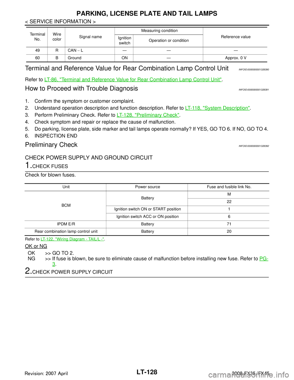
Terminal and Reference Value for Re ar Combination Lamp Control Unit
INFOID:0000000001328390
Refer to LT-86, "Terminal and Reference Value for Rear Combination Lamp Control Unit".
How to Proceed with Trouble DiagnosisINFOID:0000000001328391
1. Confirm the symptom or customer complaint.
2. Understand operation description and function description. Refer to LT-118, "
System Description".
3. Perform Preliminary Check. Refer to LT-128, "
Preliminary Check".
4. Check symptom and repair or r eplace the cause of malfunction.
5. Do parking, license plate, side marker and tail lamps operate normally? If YES, GO TO 6. If NO, GO TO 4.
6. INSPECTION END
Preliminary CheckINFOID:0000000001328392
CHECK POWER SUPPLY AND GROUND CIRCUIT
1.CHECK FUSES
Check for blown fuses.
Refer to LT- 1 2 2 , "Wiring Diagram - TAIL/L -".
OK or NG
OK >> GO TO 2.
NG >> If fuse is blown, be sure to eliminate caus e of malfunction before installing new fuse. Refer to PG-
3.
2.CHECK POWER SUPPLY CIRCUIT
49 R CAN − L— — —
60 B Ground ON — Approx. 0 V
Te r m i n a l
No. Wire
color Signal name Measuring condition
Reference value
Ignition
switch Operation or condition
Unit Power source Fuse and fusible link No.
BCM Battery
M
22
Ignition switch ON or START position 1 Ignition switch ACC or ON position 6
IPDM E/R Battery 71
Rear combination lamp control unit Battery 20
3AA93ABC3ACD3AC03ACA3AC03AC63AC53A913A773A893A873A873A8E3A773A983AC73AC93AC03AC3
3A893A873A873A8F3A773A9D3AAF3A8A3A8C3A863A9D3AAF3A8B3A8C
Page 3232 of 3924
LT-130
< SERVICE INFORMATION >
PARKING, LICENSE PLATE AND TAIL LAMPS
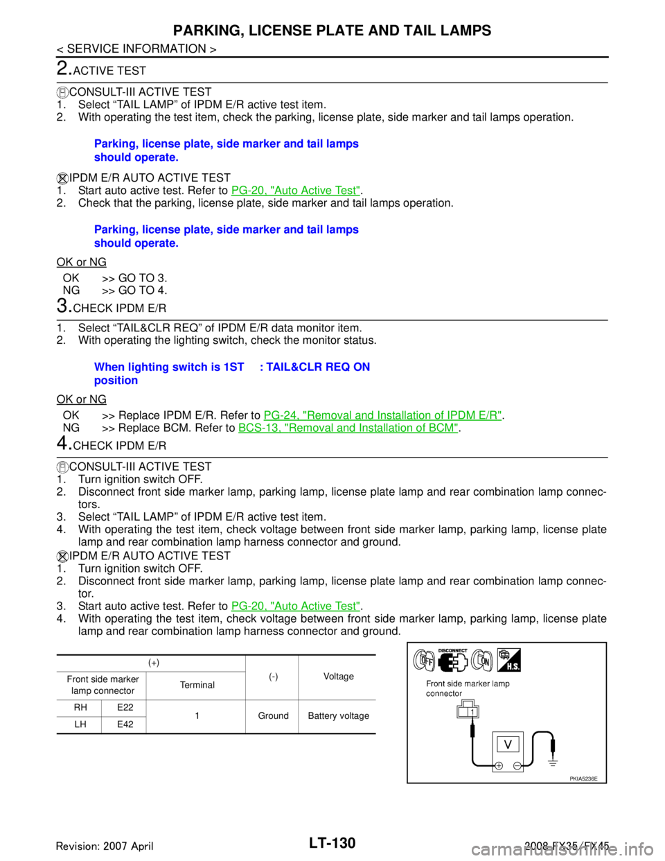
2.ACTIVE TEST
CONSULT-III ACTIVE TEST
1. Select “TAIL LAMP” of IPDM E/R active test item.
2. With operating the test item, check the parking, license plate, side marker and tail lamps operation.
IPDM E/R AUTO ACTIVE TEST
1. Start auto active test. Refer to PG-20, "
Auto Active Test".
2. Check that the parking, license plate, side marker and tail lamps operation.
OK or NG
OK >> GO TO 3.
NG >> GO TO 4.
3.CHECK IPDM E/R
1. Select “TAIL&CLR REQ” of IPDM E/R data monitor item.
2. With operating the lighting switch, check the monitor status.
OK or NG
OK >> Replace IPDM E/R. Refer to PG-24, "Removal and Installation of IPDM E/R".
NG >> Replace BCM. Refer to BCS-13, "
Removal and Installation of BCM".
4.CHECK IPDM E/R
CONSULT-III ACTIVE TEST
1. Turn ignition switch OFF.
2. Disconnect front side marker lamp, parking lamp, license plate lamp and rear combination lamp connec- tors.
3. Select “TAIL LAMP” of IPDM E/R active test item.
4. With operating the test item, check voltage between fr ont side marker lamp, parking lamp, license plate
lamp and rear combination lamp harness connector and ground.
IPDM E/R AUTO ACTIVE TEST
1. Turn ignition switch OFF.
2. Disconnect front side marker lamp, parking lamp, license plate lamp and rear combination lamp connec-
tor.
3. Start auto active test. Refer to PG-20, "
Auto Active Test".
4. With operating the test item, check voltage between fr ont side marker lamp, parking lamp, license plate
lamp and rear combination lamp harness connector and ground. Parking, license plate, side marker and tail lamps
should operate.
Parking, license plate, side marker and tail lamps
should operate.
When lighting switch is 1ST
position
: TAIL&CLR REQ ON
(+)
(-) Voltage
Front side marker
lamp connector Te r m i n a l
RH E22 1 Ground Battery voltage
LH E42
PKIA5236E
3AA93ABC3ACD3AC03ACA3AC03AC63AC53A913A773A893A873A873A8E3A773A983AC73AC93AC03AC3
3A893A873A873A8F3A773A9D3AAF3A8A3A8C3A863A9D3AAF3A8B3A8C
Page 3241 of 3924

INTERIOR ROOM LAMPLT-139
< SERVICE INFORMATION >
C
DE
F
G H
I
J
L
M A
B
LT
N
O P
Ignition keyhole illumination turns ON at time when dr iver door is opened (door switch ON) or removed keyfob
from key cylinder. Illumination turns OFF when driver door is closed (door switch OFF).
Step lamp turns ON at time when driver door or pa ssenger door is opened (door switch ON). Lamp turns OFF
when the driver, passenger doors are closed (all door switches OFF).
POWER SUPPLY AND GROUND
Power is supplied at all times (without Intelligent Key system)
through 15A fuse [No. 22, located in fuse block (J/B)]
to key switch terminal 2 and
to BCM terminal 42,
through 50A fusible link (letter M, located in fuse, fusible link and relay box)
to BCM terminal 55,
through 10A fuse [No. 19, located in fuse block (J/B)]
to combination meter terminal 8.
Power is supplied at all times (with Intelligent Key system)
through 10A fuse (No.38, located in fuse, fusible link and relay box)
to key switch and ignition knob switch terminal 1,
through 15A fuse [No.22, located in fuse block (J/B)]
to BCM terminal 42 and
to key switch and ignition knob switch terminal 3,
through 50A fusible link (letter M, located in fuse, fusible link and relay box)
to BCM terminal 55,
through 10A fuse [No. 19, located in fuse block (J/B)]
to combination meter terminal 8.
When key plate inserted to key switch, power is supplied (without Intelligent Key system)
through key switch terminal 1
to BCM terminal 37.
When inserted key plate to key switch, power is supplied (with Intelligent Key system)
through key switch and ignition knob switch terminal 4
to BCM terminal 37.
When moved ignition knob switch, power is supplied (with Intelligent Key system)
through ignition knob switch terminal 2
to intelligent key unit terminal 27.
With ignition switch in the ON or START position, power is supplied
through 15A fuse [No. 1, located in fuse block (J/B)]
to BCM terminal 38,
through 10A fuse [No. 14, located in fuse block (J/B)]
to combination meter terminal 7.
Ground is supplied
to BCM terminals 49 and 52, and
to combination meter terminal 5, 6 and 15
through grounds terminals M35, M45 and M85.
When driver side door is opened, ground is supplied
to BCM terminal 62
through front door switch (driver side) terminal 1
through case ground of front door switch (driver side).
When passenger side door is opened, ground is supplied
to BCM terminal 12
through front door switch (passenger side) terminal 1
through case ground of front door switch (passenger side).
When rear door RH is opened, ground is supplied
to BCM terminal 13, and
to personal lamp RH terminal 1
through rear door switch RH terminal 1
through case ground of rear door switch RH.
When rear door LH is opened, ground is supplied
to BCM terminal 63, and
to personal lamp LH terminal 1
through rear door switch LH terminal 1
through case ground of rear door switch LH.
When driver side door is unlocked by door lock and unlock switch, BCM receives a ground signal
through grounds terminals M35, M45 and M85
3AA93ABC3ACD3AC03ACA3AC03AC63AC53A913A773A893A873A873A8E3A773A983AC73AC93AC03AC3
3A893A873A873A8F3A773A9D3AAF3A8A3A8C3A863A9D3AAF3A8B3A8C