2008 INFINITI FX35 no start
[x] Cancel search: no startPage 3345 of 3924
MA-28
< SERVICE INFORMATION >
CHASSIS AND BODY MAINTENANCE
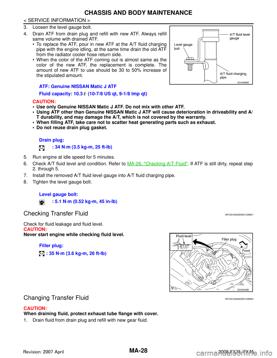
3. Loosen the level gauge bolt.
4. Drain ATF from drain plug and refill with new ATF. Always refillsame volume with drained ATF.
To replace the ATF, pour in new ATF at the A/T fluid charging
pipe with the engine idling, at the same time drain the old ATF
from the radiator cooler hose return side.
When the color of the ATF coming out is almost same as the color of the new ATF, the replacement is complete. The
amount of new ATF to use should be 30 to 50% increase of
the stipulated amount.
CAUTION:
Use only Genuine NISSAN Matic J ATF. Do not mix with other ATF.
Using ATF other than Genuine NISSAN Matic J AT F will cause deterioration in driveability and A/
T durability, and may damage the A/T, which is not covered by the warranty.
When filling ATF, take care not to scatter heat generating parts such as exhaust.
Do not reuse drain plug gasket.
5. Run engine at idle speed for 5 minutes.
6. Check A/T fluid level and condition. Refer to MA-26, "
Checking A/T Fluid". If ATF is still dirty, repeat step
2. through 5.
7. Install the removed A/T fluid level gauge into A/T fluid charging pipe.
8. Tighten the level gauge bolt.
Checking Transfer FluidINFOID:0000000001328921
Check for fluid leakage and fluid level.
CAUTION:
Never start engine while checking fluid level.
Changing Transfer FluidINFOID:0000000001328922
CAUTION:
When draining fluid, protect exh aust tube flange with cover.
1. Drain fluid from drain plug and refill with new gear fluid. ATF: Genuine NISSAN Matic J ATF
Fluid capacity: 10.3 (10-7/8 US qt, 9-1/8 lmp qt)
Drain plug:
: 34 N·m (3.5 kg-m, 25 ft-lb)
Level gauge bolt: : 5.1 N·m (0.52 kg-m, 45 in-lb)
SCIA4896E
Filler plug:
: 35 N·m (3.6 kg-m, 26 ft-lb)
SDIA2028E
3AA93ABC3ACD3AC03ACA3AC03AC63AC53A913A773A893A873A873A8E3A773A983AC73AC93AC03AC3
3A893A873A873A8F3A773A9D3AAF3A8A3A8C3A863A9D3AAF3A8B3A8C
Page 3347 of 3924
MA-30
< SERVICE INFORMATION >
CHASSIS AND BODY MAINTENANCE
2. Check oil level.
Balancing Wheels (Bonding Weight Type)INFOID:0000000001328926
REMOVAL
Using releasing agent, remove double-faced adhesive tape from the road wheel.
CAUTION:
Be careful not to scratch th e road wheel during removal.
After removing double-faced adhesive tape, wi pe clean traces of releasing agent from the road
wheel.
WHEEL BALANCE ADJUSTMENT
If a tire balance machine has adhesion balance weight mode settings and drive-in weight mode setting,
select and adjust a drive-in weight mode suitable for road wheels.
1. Set road wheel on tire balance machine using the center hole as a guide. Start the tire balance machine.
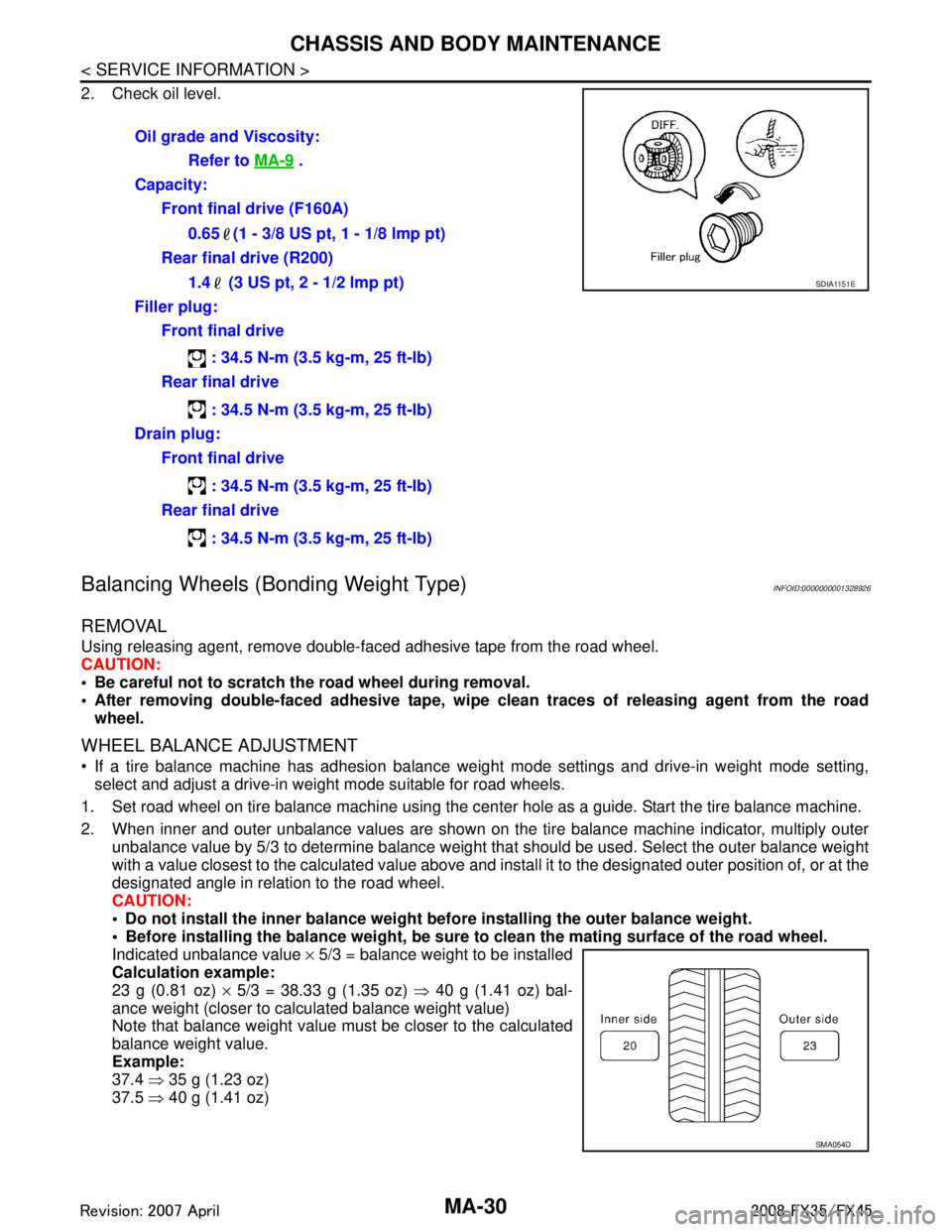
2. When inner and outer unbalance values are shown on the tire balance machine indicator, multiply outer unbalance value by 5/3 to determine balance weight t hat should be used. Select the outer balance weight
with a value closest to the calculated value above and inst all it to the designated outer position of, or at the
designated angle in relation to the road wheel.
CAUTION:
Do not install the inner balance weight before installing the outer balance weight.
Before installing the balance weight, be sure to clean the mating surface of the road wheel.
Indicated unbalance value × 5/3 = balance weight to be installed
Calculation example:
23 g (0.81 oz) × 5/3 = 38.33 g (1.35 oz) ⇒ 40 g (1.41 oz) bal-
ance weight (closer to calculated balance weight value)
Note that balance weight value must be closer to the calculated
balance weight value.
Example:
37.4 ⇒ 35 g (1.23 oz)
37.5 ⇒ 40 g (1.41 oz)
Oil grade and Viscosity:
Refer to MA-9
.
Capacity: Front final drive (F160A)
0.65 (1 - 3/8 US pt, 1 - 1/8 lmp pt)
Rear final drive (R200)
1.4 (3 US pt, 2 - 1/2 lmp pt)
Filler plug: Front final drive
: 34.5 N-m (3.5 kg-m, 25 ft-lb)
Rear final drive
: 34.5 N-m (3.5 kg-m, 25 ft-lb)
Drain plug: Front final drive
: 34.5 N-m (3.5 kg-m, 25 ft-lb)
Rear final drive
: 34.5 N-m (3.5 kg-m, 25 ft-lb)
SDIA1151E
SMA054D
:
Page 3348 of 3924
CHASSIS AND BODY MAINTENANCEMA-31
< SERVICE INFORMATION >
C
DE
F
G H
I
J
K
M A
B
MA
N
O P
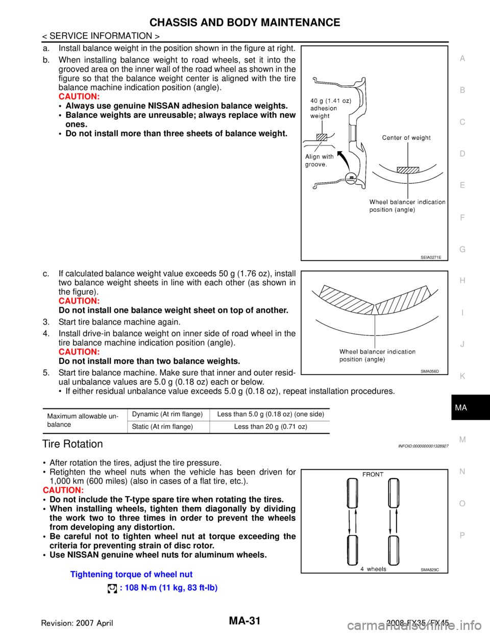
a. Install balance weight in the position shown in the figure at right.
b. When installing balance weight to road wheels, set it into the grooved area on the inner wall of the road wheel as shown in the
figure so that the balance weight center is aligned with the tire
balance machine indication position (angle).
CAUTION:
Always use genuine NISSAN adhesion balance weights.
Balance weights are unreusable; always replace with newones.
Do not install more than three sheets of balance weight.
c. If calculated balance weight value exceeds 50 g (1.76 oz), install two balance weight sheets in line with each other (as shown in
the figure).
CAUTION:
Do not install one balance weig ht sheet on top of another.
3. Start tire balance machine again.
4. Install drive-in balance weight on inner side of road wheel in the tire balance machine indication position (angle).
CAUTION:
Do not install more than two balance weights.
5. Start tire balance machine. Make sure that inner and outer resid- ual unbalance values are 5.0 g (0.18 oz) each or below.
If either residual unbalance value exceeds 5.0 g (0.18 oz), repeat installation procedures.
Tire RotationINFOID:0000000001328927
After rotation the tires, adjust the tire pressure.
Retighten the wheel nuts when the vehicle has been driven for
1,000 km (600 miles) (also in cases of a flat tire, etc.).
CAUTION:
Do not include the T-type spare tire when rotating the tires.
When installing wheels, tighte n them diagonally by dividing
the work two to three times in order to prevent the wheels
from developing any distortion.
Be careful not to tighten wh eel nut at torque exceeding the
criteria for preventing strain of disc rotor.
Use NISSAN genuine wheel nu ts for aluminum wheels.
SEIA0271E
Maximum allowable un-
balanceDynamic (At rim flange) Less than 5.0 g (0.18 oz) (one side)
Static (At rim flange) Less than 20 g (0.71 oz)
SMA056D
Tightening torque of wheel nut
: 108 N·m (11 kg, 83 ft-lb)SMA829C
3AA93ABC3ACD3AC03ACA3AC03AC63AC53A913A773A893A873A873A8E3A773A983AC73AC93AC03AC3
3A893A873A873A8F3A773A9D3AAF3A8A3A8C3A863A9D3AAF3A8B3A8C
Page 3376 of 3924
PG-12
< SERVICE INFORMATION >
POWER SUPPLY ROUTING CIRCUIT
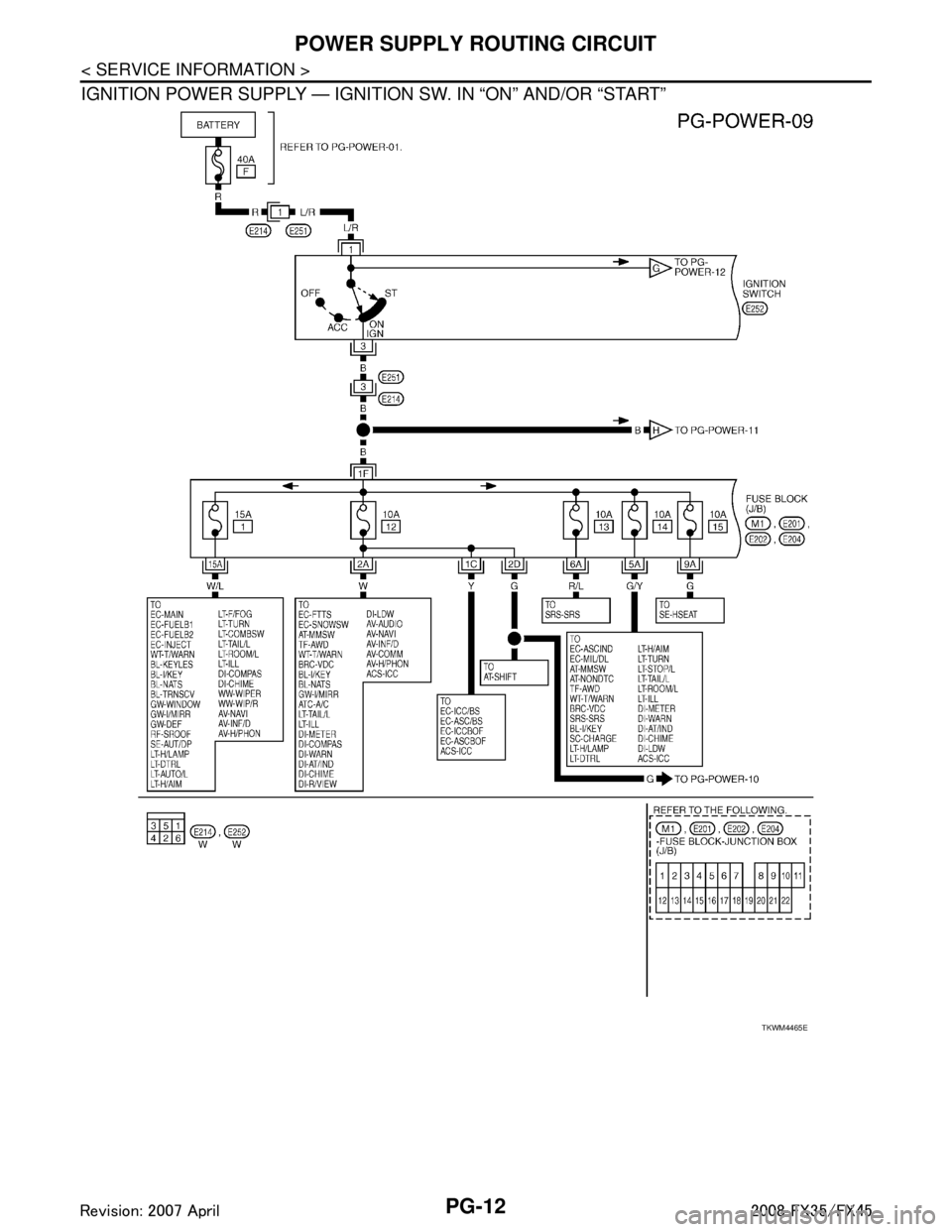
IGNITION POWER SUPPLY — IGNITION SW. IN “ON” AND/OR “START”
TKWM4465E
3AA93ABC3ACD3AC03ACA3AC03AC63AC53A913A773A893A873A873A8E3A773A983AC73AC93AC03AC3
3A893A873A873A8F3A773A9D3AAF3A8A3A8C3A863A9D3AAF3A8B3A8C
Page 3383 of 3924

IPDM E/R (INTELLIGENT POWER DISTRIBUTION MODULE ENGINE ROOM)
PG-19
< SERVICE INFORMATION >
C
D E
F
G H
I
J
L
M A
B
PG
N
O P
NOTE: The details for display of the period are as follows:
CRNT: Error currently de tected with IPDM E/R.
PAST: Error detected in the past and memorized with IPDM E/R.
DATA MONITOR
NOTE:
Perform monitoring of IPDM E/R data with the ignition switch ON. When the ignition switch is at ACC, the display may not be co rrect.
*1: The vehicle without the Intelligent Key system displays only ON without change.
*2:The cornering lamp item is displayed, but it cannot be monitored.
ACTIVE TEST
DTC Display Items Malfunction detecting condition TIME
Possible causes
CRNT PAST
— NO DTC IS DETECT-
ED.FURTHER TEST-
ING MAY BE
REQUIRED. ————
U1000 CAN COMM CIRCUIT If CAN communication reception/transmission
data has a malfunction, or if any of the control
units malfunction, data reception/transmission
cannot be confirmed.
When the data in CAN communication is not re- ceived before the specified time ××
Any of or several items
below have errors.
TRANSMIT DIAG
ECM
BCM/SEC
Item name
CONSULT-III screen dis-
play Display or unit MAIN SIG-
NALS Description
Motor fan request MOTOR FAN REQ 1/2/3/4 ×Signal status input from ECM
Compressor request A C COMP REQ On/Off ×Signal status input from ECM
Tail & clear request TAIL&CLR REQ On/Off ×Signal status input from BCM
H/L LO request HL LO REQ On/Off ×Signal status input from BCM
H/L HI request HL HI REQ On/Off ×Signal status input from BCM
FR fog request FR FOG REQ On/Off ×Signal status input from BCM
FR wiper request FR WIP REQ Stop/1LOW/Lo/Hi ×Signal status input from BCM
Wiper auto stop WIP AUTO STOP ACT P/STOP P ×Output status of IPDM E/R
Wiper protection WIP PROT Off/BLOCK ×Control status of IPDM E/R
Starter request ST RLY REQ
*1On/Off Status of input signal
Ignition relay status IGN RLY On/Off ×Ignition relay status monitored with
IPDM E/R
Rear window defogger re-
quest RR DEF REQ On/Off
×Signal status input from BCM
Oil pressure switch OIL P SW Open/Close Signal status input in IPDM E/R
Hood switch HOOD SW On/Off Input signal status
Theft warning horn re-
quest THFT HRN REQ On/Off Signal st
atus input from BCM
Horn chirp HORN CHIRP On/Off Ou tput status of IPDM E/R
Cornering lamp request CRNRNG LMP REQ
*2Off Signal status input from BCM
Test item CONSULT-III screen display Description
Tail lamp operation TAIL LAMP With a certain On-Off operation, the tail lamp relay can be operated.
Rear window defogger opera-
tion REAR DEFOGGER
With a certain On-Off operation, the rear window defogger relay can be
operated.
3AA93ABC3ACD3AC03ACA3AC03AC63AC53A913A773A893A873A873A8E3A773A983AC73AC93AC03AC3
3A893A873A873A8F3A773A9D3AAF3A8A3A8C3A863A9D3AAF3A8B3A8C
Page 3384 of 3924
PG-20
< SERVICE INFORMATION >
IPDM E/R (INTELLIGENT POWER DISTRIBUTION MODULE ENGINE ROOM)
NOTE:
This item is displayed, but cannot be tested.
Auto Active TestINFOID:0000000001328875
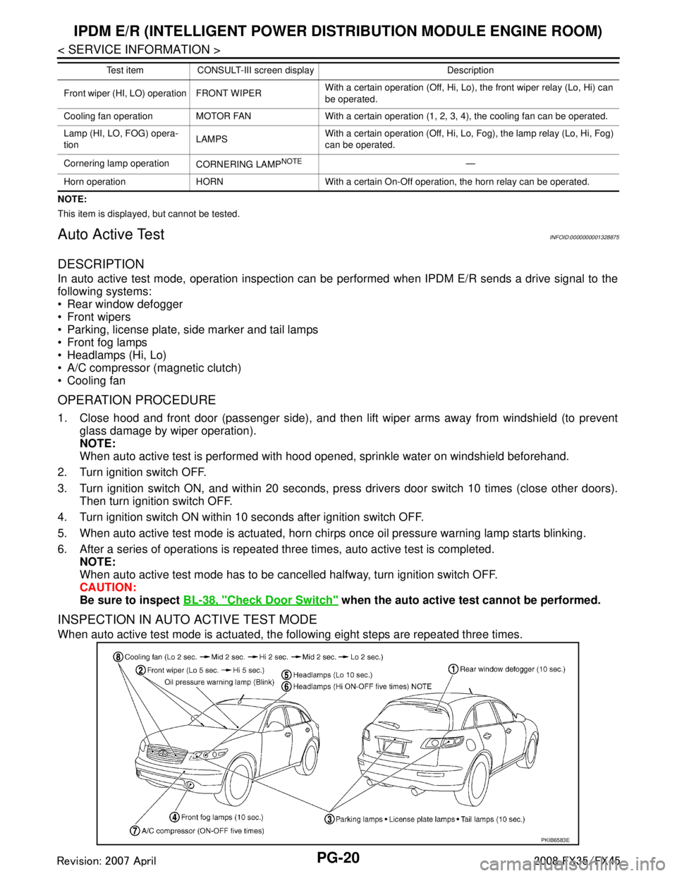
DESCRIPTION
In auto active test mode, operation inspection can be performed when IPDM E/R sends a drive signal to the
following systems:
Rear window defogger
Front wipers
Parking, license plate, side marker and tail lamps
Front fog lamps
Headlamps (Hi, Lo)
A/C compressor (magnetic clutch)
Cooling fan
OPERATION PROCEDURE
1. Close hood and front door (passenger side), and then lift wiper arms away from windshield (to prevent
glass damage by wiper operation).
NOTE:
When auto active test is performed with hood opened, sprinkle water on windshield beforehand.
2. Turn ignition switch OFF.
3. Turn ignition switch ON, and within 20 seconds, pre ss drivers door switch 10 times (close other doors).
Then turn ignition switch OFF.
4. Turn ignition switch ON within 10 seconds after ignition switch OFF.
5. When auto active test mode is actuated, horn chir ps once oil pressure warning lamp starts blinking.
6. After a series of operations is repeated three times, auto active test is completed. NOTE:
When auto active test mode has to be cancelled halfway, turn ignition switch OFF.
CAUTION:
Be sure to inspect BL-38, "
Check Door Switch" when the auto active t est cannot be performed.
INSPECTION IN AUTO ACTIVE TEST MODE
When auto active test mode is actuated, the following eight steps are repeated three times.
Front wiper (HI, LO) operation FRONT WIPER With a certain operation (Off, Hi, Lo),
the front wiper relay (Lo, Hi) can
be operated.
Cooling fan operation MOTOR FAN With a certain operation (1, 2, 3, 4), the cooling fan can be operated.
Lamp (HI, LO, FOG) opera-
tion LAMPSWith a certain operation (Off, Hi, Lo, Fog), the lamp relay (Lo, Hi, Fog)
can be operated.
Cornering lamp operation CORNERING LAMP
NOTE—
Horn operation HORN With a certain On-Off operation, the horn relay can be operated. Test item CONSULT-III screen display Description
PKIB6583E
3AA93ABC3ACD3AC03ACA3AC03AC63AC53A913A773A893A873A873A8E3A773A983AC73AC93AC03AC3
3A893A873A873A8F3A773A9D3AAF3A8A3A8C3A863A9D3AAF3A8B3A8C
Page 3427 of 3924

HARNESSPG-63
< SERVICE INFORMATION >
C
DE
F
G H
I
J
L
M A
B
PG
N
O P
PHSB1 EC Camshaft Position Sensor (PHASE) (Bank 1)
PHSB2 EC Camshaft Position Sensor (PHASE) (Bank 2)
PNP/SW AT Park/Neutral Position Switch
PNP/SW EC Park/Neutral Position Switch
POS EC Crankshaft Position Sensor (CKPS) (POS)
POWER PG Power Supply Routing
PRE/SE EC EVAP Control System Pressure Sensor
PS/SEN EC Power Steering Pressure Sensor
R/VIEW DI Rear View Ca mera Control System
ROOM/L LT Interior Room Lamp
RP/SEN EC Refrigerant Pressure Sensor
SEAT SE Power Seat
SEN/PW EC Sensor Power Supply
SHIFT AT A/T Shift Lock System
SNOWSW EC Snow Mode Switch
SROOF RF Sunroof
SRS SRS Supplemental Restraint System
START SC Starting System
STOP/L LT Stop Lamp
STSIG AT Start Signal Circuit
T/WARN WT Low Tire Pressure Warning System
TAIL/L LT Parking, License and Tail Lamps
TPS1 EC Throttle Position Sensor (Sensor 1)
TPS2 EC Throttle Position Sensor (Sensor 2)
TPS3 EC Throttle Position Sensor
TRNSCV BL Homelink Universal Transceiver
TURN LT Turn Signal and Hazard Warning Lamp
VDC BRC Vehicle Dynamics Control System
VEHSEC BL Vehicle Security System
VENT/V EC EVAP Canister Vent Control Valve
VIAS EC Variable Induction Air Control System
VIAS/V EC VIAS Control Solenoid Valve
VSSA/T AT Vehicle Sp eed Sensor A/T (Revolution Sensor)
WARN DI Warning Lamps
WINDOW GW Power Window
WIP/R WW Rear Wiper and Washer
WIPER WW Front Wiper and Washer Code Section Wiring Diagram Name
3AA93ABC3ACD3AC03ACA3AC03AC63AC53A913A773A893A873A873A8E3A773A983AC73AC93AC03AC3
3A893A873A873A8F3A773A9D3AAF3A8A3A8C3A863A9D3AAF3A8B3A8C
Page 3457 of 3924

PS-2
< SERVICE INFORMATION >
PRECAUTIONS
SERVICE INFORMATION
PRECAUTIONS
Precaution for Supplemental Restraint System (SRS) "AIR BAG" and "SEAT BELT
PRE-TENSIONER"
INFOID:0000000001612911
The Supplemental Restraint System such as “A IR BAG” and “SEAT BELT PRE-TENSIONER”, used along
with a front seat belt, helps to reduce the risk or severi ty of injury to the driver and front passenger for certain
types of collision. This system includes seat belt switch inputs and dual stage front air bag modules. The SRS
system uses the seat belt switches to determine the front air bag deployment, and may only deploy one front
air bag, depending on the severity of a collision and w hether the front occupants are belted or unbelted.
Information necessary to service the system safely is included in the “SUPPLEMENTAL RESTRAINT SYS-
TEM” and “SEAT BELTS” of this Service Manual.
WARNING:
• To avoid rendering the SRS inopera tive, which could increase the risk of personal injury or death in
the event of a collision which would result in air bag inflation, all maintenance must be performed by
an authorized NISS AN/INFINITI dealer.
Improper maintenance, including in correct removal and installation of the SRS, can lead to personal
injury caused by unintent ional activation of the system. For re moval of Spiral Cable and Air Bag
Module, see the “SUPPLEMEN TAL RESTRAINT SYSTEM”.
Do not use electrical test equipmen t on any circuit related to the SRS unless instructed to in this
Service Manual. SRS wiring harnesses can be identi fied by yellow and/or orange harnesses or har-
ness connectors.
Precaution Necessary for Steering W heel Rotation After Battery Disconnect
INFOID:0000000001612914
NOTE:
This Procedure is applied only to models with In telligent Key system and NVIS/IVIS (NISSAN/INFINITI
VEHICLE IMMOBILIZER SYSTEM - NATS).
Remove and install all control units after disconnecting both battery cables with the ignition knob in the ″LOCK ″ position.
Always use CONSULT-III to perform self-diagnosis as a part of each function inspection after finishing work.
If DTC is detected, perform trouble diagnosis according to self-diagnostic results.
For models equipped with the Intelligent Key system and NVIS /IVIS, an electrically controlled steering lock
mechanism is adopted on the key cylinder.
For this reason, if the battery is disconnected or if the battery is discharged, the steering wheel will lock and
steering wheel rotation will become impossible.
If steering wheel rotation is required when battery pow er is interrupted, follow the procedure below before
starting the repair operation.
OPERATION PROCEDURE
1. Connect both battery cables. NOTE:
Supply power using jumper cables if battery is discharged.
2. Use the Intelligent Key or mechanical key to turn the ignition switch to the ″ACC ″ position. At this time, the
steering lock will be released.
3. Disconnect both battery cables. The steering lock will remain released and the steering wheel can be
rotated.
4. Perform the necessary repair operation.
5. When the repair work is completed, return the ignition switch to the ″LOCK ″ position before connecting
the battery cables. (At this time, the steering lock mechanism will engage.)
6. Perform a self-diagnosis check of all control units using CONSULT-III.
Precaution for Steering SystemINFOID:0000000001327705
In case of removing steering gear assembly, make the final tightening with grounded and unloaded vehicle
condition, and then check wheel alignment.
Observe the following precautions when disassembling.
3AA93ABC3ACD3AC03ACA3AC03AC63AC53A913A773A893A873A873A8E3A773A983AC73AC93AC03AC3
3A893A873A873A8F3A773A9D3AAF3A8A3A8C3A863A9D3AAF3A8B3A8C