2008 INFINITI FX35 no start
[x] Cancel search: no startPage 3630 of 3924
CHARGING SYSTEMSC-21
< SERVICE INFORMATION >
C
DE
F
G H
I
J
L
M A
B
SC
N
O P
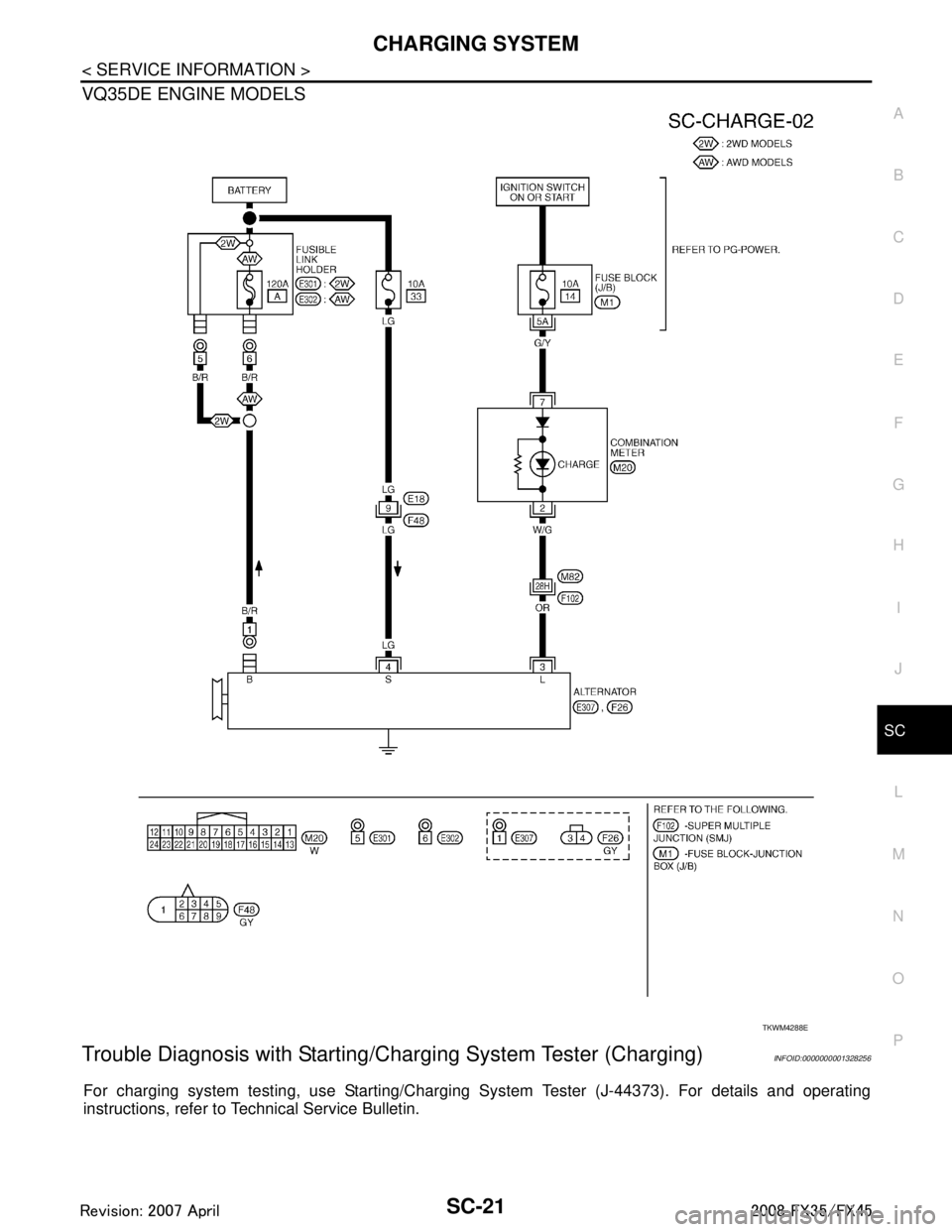
VQ35DE ENGINE MODELS
Trouble Diagnosis with Starting/Ch arging System Tester (Charging)INFOID:0000000001328256
For charging system testing, use Starting/Chargi ng System Tester (J-44373). For details and operating
instructions, refer to Technical Service Bulletin.
TKWM4288E
3AA93ABC3ACD3AC03ACA3AC03AC63AC53A913A773A893A873A873A8E3A773A983AC73AC93AC03AC3
3A893A873A873A8F3A773A9D3AAF3A8A3A8C3A863A9D3AAF3A8B3A8C
Page 3632 of 3924
CHARGING SYSTEMSC-23
< SERVICE INFORMATION >
C
DE
F
G H
I
J
L
M A
B
SC
N
O P
Check if battery terminals are clean and tight.
OK or NG
OK >> GO TO 2.
NG >> Repair battery terminals connection.
2.CHECK FUSE AND FUSIBLE LINK
Check for blown alternator and combination meter fuses.
OK or NG
OK >> GO TO 3.
NG >> If fuse is blown, be sure eliminate cause of malfunction before installing new fuse.
3.CHECK “E” TERMINAL CONNECTION
Check if “E” terminal (alternator ground harness) is clean and tight.
OK or NG
OK >> GO TO 4.
NG >> Repair “E” terminal connection.
4.CHECK ALTERNATOR DRIVE BELT TENSION
Check alternator drive belt tension. Refer to EM-170, "
Checking Drive Belts" (VK45DE) or EM-14, "Checking
Drive Belts" (VQ35DE).
OK or NG
OK >> INSPECTION END
NG >> Repair as needed.
DIAGNOSTIC PROCEDURE 1
Check “L” Terminal Circuit (Open)
1.CHECK “L” TERMINAL CONNECTION
1. Turn ignition switch OFF.
2. Check if “L” terminal is clean and tight.
OK or NG
OK >> GO TO 2.
NG >> Repair “L” terminal connection. Confirm repa ir by performing complete Starting/Charging system
test. Refer to Technical Service Bulletin.
2.CHECK “L” TERMINAL CIRCUIT (OPEN)
1. Disconnect alternator connector.
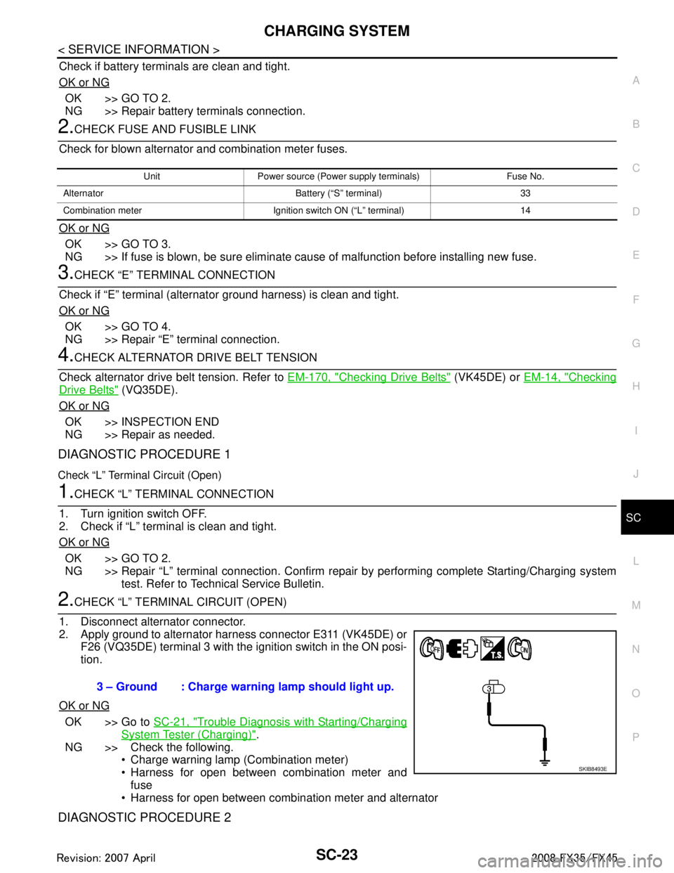
2. Apply ground to alternator harness connector E311 (VK45DE) or F26 (VQ35DE) terminal 3 with the ignition switch in the ON posi-
tion.
OK or NG
OK >> Go to SC-21, "Trouble Diagnosis with Starting/Charging
System Tester (Charging)".
NG >> Check the following. Charge warning lamp (Combination meter)
Harness for open between combination meter and
fuse
Harness for open between combination meter and alternator
DIAGNOSTIC PROCEDURE 2
Unit Power source (Power supply terminals) Fuse No.
Alternator Battery (“S” terminal) 33
Combination meter Ignition switch ON (“L” terminal) 14
3 – Ground : Charge warning lamp should light up.
SKIB8493E
3AA93ABC3ACD3AC03ACA3AC03AC63AC53A913A773A893A873A873A8E3A773A983AC73AC93AC03AC3
3A893A873A873A8F3A773A9D3AAF3A8A3A8C3A863A9D3AAF3A8B3A8C
Page 3633 of 3924
SC-24
< SERVICE INFORMATION >
CHARGING SYSTEM
Check “L” Terminal Circuit (Short)
1.CHECK “L” TERMINAL CIRCUIT (SHORT)
1. Turn ignition switch OFF.
2. Disconnect alternator connector.
3. Turn ignition switch ON.
Charge warning lamp should light up?
YES >> Check the following. Harness for short between combination meter and alternator
Charge warning lamp (Combination meter)
NO >> Go to SC-21, "
Trouble Diagnosis with Starting/Charging System Tester (Charging)".
DIAGNOSTIC PROCEDURE 3
Check “S” Terminal Circuit
1.CHECK “S” TERMINAL CONNECTION
1. Turn ignition switch OFF.
2. Check if “S” terminal is clean and tight.
OK or NG
OK >> GO TO 2.
NG >> Repair “S” terminal connection. Confirm repair by performing complete Starting/Charging system
test. Refer to Technical Service Bulletin.
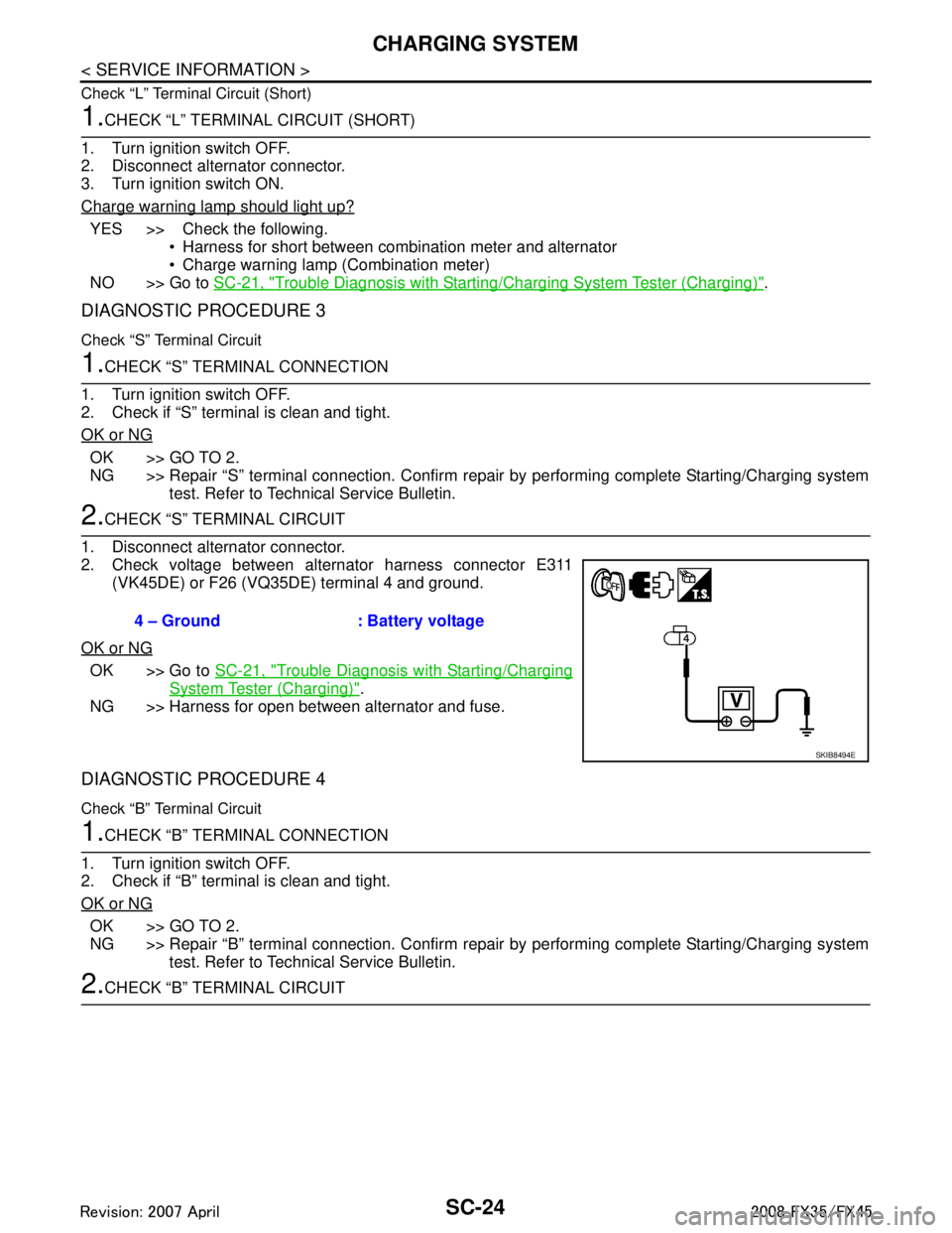
2.CHECK “S” TERMINAL CIRCUIT
1. Disconnect alternator connector.
2. Check voltage between alternator harness connector E311 (VK45DE) or F26 (VQ35DE) terminal 4 and ground.
OK or NG
OK >> Go to SC-21, "Trouble Diagnosis with Starting/Charging
System Tester (Charging)".
NG >> Harness for open between alternator and fuse.
DIAGNOSTIC PROCEDURE 4
Check “B” Terminal Circuit
1.CHECK “B” TERMINAL CONNECTION
1. Turn ignition switch OFF.
2. Check if “B” terminal is clean and tight.
OK or NG
OK >> GO TO 2.
NG >> Repair “B” terminal connection. Confirm repair by performing complete Starting/Charging system
test. Refer to Technical Service Bulletin.
2.CHECK “B” TERMINAL CIRCUIT 4 – Ground : Battery voltage
SKIB8494E
3AA93ABC3ACD3AC03ACA3AC03AC63AC53A913A773A893A873A873A8E3A773A983AC73AC93AC03AC3
3A893A873A873A8F3A773A9D3AAF3A8A3A8C3A863A9D3AAF3A8B3A8C
Page 3634 of 3924
CHARGING SYSTEMSC-25
< SERVICE INFORMATION >
C
DE
F
G H
I
J
L
M A
B
SC
N
O P
Check voltage between alternator “B” terminal E307 terminal 1 and
ground.
OK or NG
OK >> GO TO 3.
NG >> Check the following. Harness for open between alternator and fusible link
(VK45DE and VQ35DE AWD)
Harness for open between alternator and battery
(VQ35DE 2WD)
3.CHECK “B” TERMINAL CONNECT ION (VOLTAGE DROP TEST)
1. Start engine, then engine running at idle and warm.
2. Check voltage between alternator “B” terminal E307 terminal 1 and battery positive terminal.
OK or NG
OK >> Go to SC-21, "Trouble Diagnosis with Starting/Charging
System Tester (Charging)".
NG >> Check harness between battery and alternator for poor continuity.
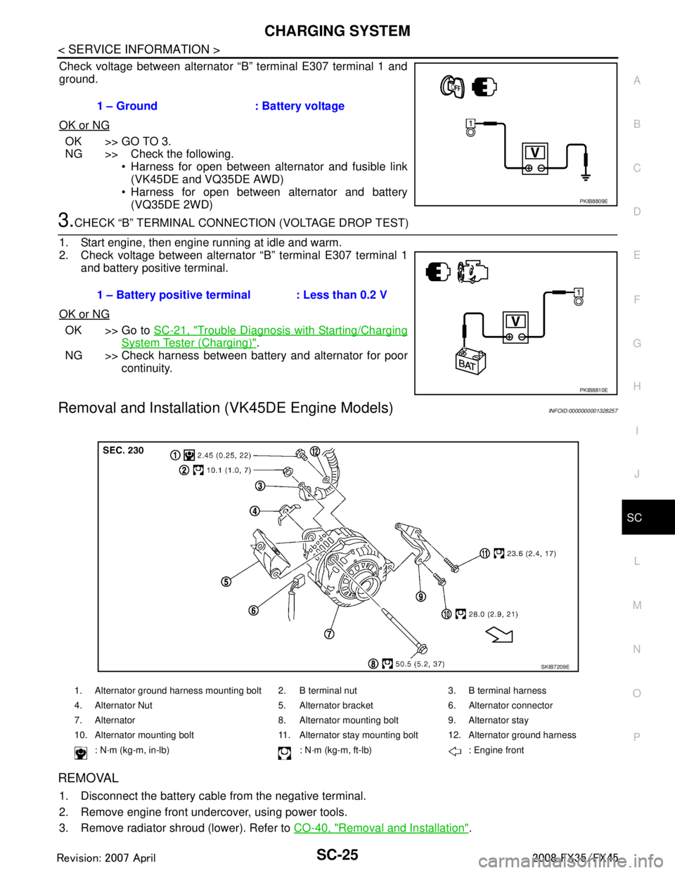
Removal and Installation (VK45DE Engine Models)INFOID:0000000001328257
REMOVAL
1. Disconnect the battery cabl e from the negative terminal.
2. Remove engine front undercover, using power tools.
3. Remove radiator shroud (lower). Refer to CO-40, "
Removal and Installation".
1 – Ground : Battery voltage
PKIB8809E
1 – Battery positive terminal : Less than 0.2 V
PKIB8810E
1. Alternator ground harness mounting bolt 2. B terminal nut 3. B terminal harness
4. Alternator Nut 5. Alternator bracket 6. Alternator connector
7. Alternator 8. Alternator mounting bolt 9. Alternator stay
10. Alternator mounting bolt 11. Alternator stay mounting bolt 12. Alternator ground harness
: N·m (kg-m, in-lb) : N·m (kg-m, ft-lb) : Engine front
SKIB7209E
3AA93ABC3ACD3AC03ACA3AC03AC63AC53A913A773A893A873A873A8E3A773A983AC73AC93AC03AC3
3A893A873A873A8F3A773A9D3AAF3A8A3A8C3A863A9D3AAF3A8B3A8C
Page 3639 of 3924

SC-30
< SERVICE INFORMATION >
SERVICE DATA AND SPECIFICATIONS (SDS)
SERVICE DATA AND SPECIFICATIONS (SDS)
BatteryINFOID:0000000001328260
StarterINFOID:0000000001328261
AlternatorINFOID:0000000001328262
Typ e11 0 D 2 6 L
Capacity V - AH 12 - 75
Cold cranking current (F or reference value) A 720
Applied model VK45DE VQ3 5DE (2WD) VQ35DE (AWD)
Ty p e M002T85075 S114-880A S114-881A
MITSUBISHI make HITACHI make Reduction gear type
System voltage V 12
No-load Te r m i n a l v o l t a g e V 11
Current A Less than 145 Less than 90
Revolution rpm More than 3,300 More than 2,880
Minimum diameter of commutator mm (in) 31.4 (1.236) 28.0 (1.102)
Minimum length of brush mm (in) 11.0 (0.433) 10.5 (0.413)
Brush spring tension N (kg, lb) 26.7 - 36.1
(2.72 - 3.68,
6.80 - 8.12) 16.2 (1.65, 3.6)
Clearance between bearing metal and armature shaft mm (in) Less than 0.2 (0.008)
Clearance between pinion front edge and pinion stopper mm (in) 0.5 - 2.0
(0.020 - 0.079) —
Movement in height of pinion assembly mm (in) — 0.3 - 2.5 (0.012 - 0.098)
Applied model VK45DE VQ35DE
Ty p e LR1110 - 716B A3TG0191
HITACHI make MITSUBISHI make
Nominal rating V - A 12 - 110
Ground polarity Negative
Minimum revolution under no-load (When 13.5 V is applied) rpm Less than 1,100 Less than 1,000
Hot output current (When 13.5 V is applied) A/rpm More than 70/1,800
More than 91/2,500
More than 110/5,000 More than 37/1,300
More than 92/2,500
More than 103/5,000
Regulated output voltage V 14.1 - 14.7
Minimum length of brush mm (in) More than 6.00 (0.236) More than 5.00 (0.197)
Brush spring pressure N (g, oz) 1.00 - 3.43
(102 - 350, 3.60 - 12.34) 4.8 - 6.0
(490 - 612, 17.28 - 21.60)
Slip ring minimum outer diameter mm (in) More than 26.0 (1.024) More than 22.1 (0.870)
Rotor (Field coil) resistance Ω2.31 1.7 - 2.1
3AA93ABC3ACD3AC03ACA3AC03AC63AC53A913A773A893A873A873A8E3A773A983AC73AC93AC03AC3
3A893A873A873A8F3A773A9D3AAF3A8A3A8C3A863A9D3AAF3A8B3A8C
Page 3647 of 3924

SE-8
< SERVICE INFORMATION >
SQUEAK AND RATTLE TROUBLE DIAGNOSES
Insulates where slight movement is present. Ideal for instrument panel applications.
SILICONE GREASE
Used in place of UHMW tape that will be visible or not fit.
Note: Will only last a few months.
SILICONE SPRAY
Use when grease cannot be applied.
DUCT TAPE
Use to eliminate movement.
CONFIRM THE REPAIR
Confirm that the cause of a noise is repaired by test driving the vehicle. Operate the vehicle under the same
conditions as when the noise originally occurred. Refer to the notes on the Diagnostic Worksheet.
Generic Squeak and Rattle TroubleshootingINFOID:0000000001328095
Refer to Table of Contents for specific component removal and installation information.
INSTRUMENT PANEL
Most incidents are caused by contact and movement between:
1. The cluster lid A and instrument panel
2. Acrylic lens and combination meter housing
3. Instrument panel to front pillar garnish
4. Instrument panel to windshield
5. Instrument panel mounting pins
6. Wiring harnesses behind the combination meter
7. A/C defroster duct and duct joint
These incidents can usually be located by tapping or moving the components to duplicate the noise or by
pressing on the components while driving to stop the noi se. Most of these incidents can be repaired by apply-
ing felt cloth tape or silicon spray (in hard to reach areas). Urethane pads can be used to insulate wiring har-
ness.
CAUTION:
Do not use silicone spray to isolate a squeak or ra ttle. If you saturate the area with silicone, you will
not be able to recheck the repair.
CENTER CONSOLE
Components to pay attention to include:
1. Shifter assembly cover to finisher
2. A/C control unit and cluster lid C
3. Wiring harnesses behind audio and A/C control unit
The instrument panel repair and isolation pr ocedures also apply to the center console.
DOORS
Pay attention to the:
1. Finisher and inner panel making a slapping noise
2. Inside handle escutcheon to door finisher
3. Wiring harnesses tapping
4. Door striker out of alignment causing a popping noise on starts and stops
Tapping or moving the components or pressing on them wh ile driving to duplicate the conditions can isolate
many of these incidents. You can usually insulate the areas with felt cloth tape or insulator foam blocks from
the Nissan Squeak and Rattle Kit (J-43980) to repair the noise.
TRUNK
Trunk noises are often caused by a loose jack or loose items put into the trunk by the owner.
In addition look for:
1. Trunk lid dumpers out of adjustment
2. Trunk lid striker out of adjustment
3. The trunk lid torsion bars knocking together
4. A loose license plate or bracket
3AA93ABC3ACD3AC03ACA3AC03AC63AC53A913A773A893A873A873A8E3A773A983AC73AC93AC03AC3
3A893A873A873A8F3A773A9D3AAF3A8A3A8C3A863A9D3AAF3A8B3A8C
Page 3651 of 3924

SE-12
< SERVICE INFORMATION >
AUTOMATIC DRIVE POSITIONER
AUTOMATIC DRIVE POSITIONER
System DescriptionINFOID:0000000001328097
The system automatically moves the driver seat to facilitate entry/exit to/from the vehicle. The automatic
drive positioner control unit can also store the optimum driving positions (driver seat, steering wheel position
(tilt, telescopic) and door mirror position) for 2 people. If the driver is changes, one-touch operation allows
changing to the other driving position.
The settings (ON/OFF) of the automatic sliding s eat (Entry/Exiting operation) at entry/exit can be changed
as desired, using the display unit in the center of the instrument panel. The set content is transmitted by
CAN communication, from display contro l unit to driver seat control unit.
Using CONSULT-III, the seat slide and steering wheel amount at entry/exit setting can be changed.
MANUAL OPERATION
The driving position [seat position, steering wheel posit ion (tilt, telescopic) and door mirror position] can be
adjusted with the power seat switch or ADP steering switch or door mirror remote control switch.
NOTE:
The seat can be manually operated with the ignition switch OFF.
The door mirrors can be manually operated with the ignition switch turned ACC or ON.
AUTOMATIC OPERATION
NOTE:
Disconnecting the battery erases the stored memory.
After connecting the battery, insert the key into the ignition cylinder and turn the driver door switch ON (open) →OFF (close) →ON
(open), the Entry/ Exiting operation becomes possible.
After exiting operation is carried out, return operation can be operated.
NOTE:
During automatic operation, if the ignition switch is turned ON →START, the automatic operation is suspended. When the ignition switch
returns to ON, it resumes.
MEMORY STORING AND KEYFOB INTERLOCK STORING
Store the 2 driving positions and shifts to t he stored driving position with the memory switch.
Function Description
Memory switch operation The seat, steering and door mirror move to the stored driving position by pushing
memory switch (1 or 2).
Entry/Exiting function Exiting operation At exit, the seat moves backward and steering wheel moves forward/upward.
Entry operation
At entry, the seat and steering wheel returns from the exiting position to the previous
driving position.
keyfob interlock operation Perform memory operation, exiting operation and entry operation by pressing keyfob
unlock button.
Auto operation temporary stop
conditions. When ignition switch turned to START during memory switch operation and return opera-
tion, memory switch operation and entry operation is stopped.
Auto operation stop conditions. When the vehicle speed becomes 7 km/h (4 MPH) or higher.
When the setting switch, memory switch 1, or 2 are pressed.
When A/T selector lever is in any position other than P.
When the door mirror remote control switch is operated (when ignition switch turned to
ON or ACC).
When power seat switch turned ON.
When ADP steering switch turned ON (telescopic operation or tilt operation).
When door mirror operates (only memory switch operation).
When driver seat sliding Entry/Exiting setting is OFF (only entry/exiting operation).
When steering wheel tilt and telescopic Entry/Exiting setting is OFF (only entry/exiting op-
eration).
When the tilt and telescopic sensor malfunction is detected.
3AA93ABC3ACD3AC03ACA3AC03AC63AC53A913A773A893A873A873A8E3A773A983AC73AC93AC03AC3
3A893A873A873A8F3A773A9D3AAF3A8A3A8C3A863A9D3AAF3A8B3A8C
Page 3654 of 3924
AUTOMATIC DRIVE POSITIONERSE-15
< SERVICE INFORMATION >
C
DE
F
G H
J
K L
M A
B
SE
N
O P
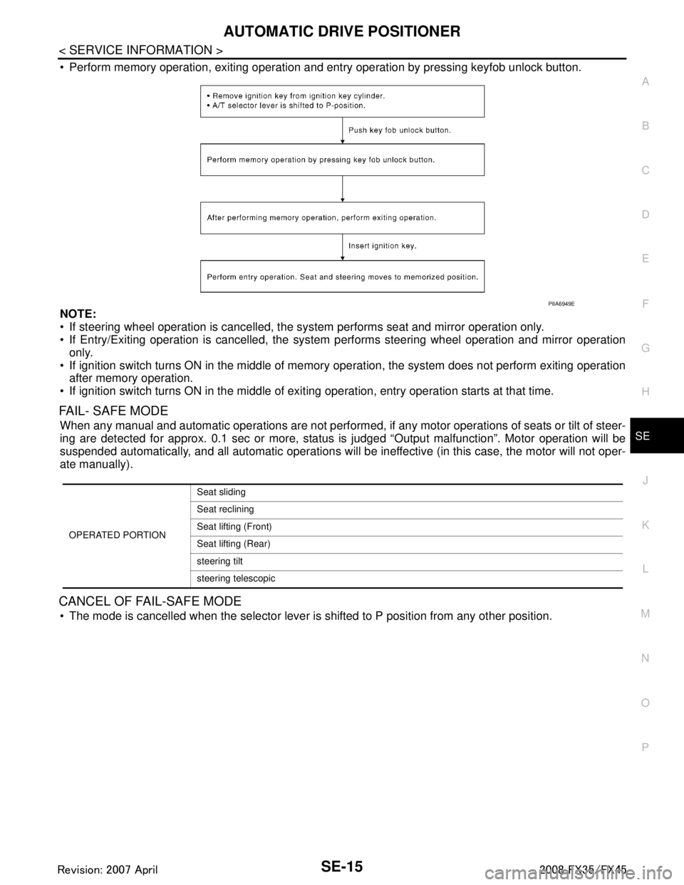
Perform memory operation, exiting operation and entry operation by pressing keyfob unlock button.
NOTE:
If steering wheel operation is cancelled, t he system performs seat and mirror operation only.
If Entry/Exiting operation is canc elled, the system performs steering wheel operation and mirror operation
only.
If ignition switch turns ON in the middle of memory operation, the system does not perform exiting operation
after memory operation.
If ignition switch turns ON in the middle of exit ing operation, entry operation starts at that time.
FAIL- SAFE MODE
When any manual and automatic operations are not performed, if any motor operations of seats or tilt of steer-
ing are detected for approx. 0.1 sec or more, status is judged “Output malfunction”. Motor operation will be
suspended automatically, and all automatic operations will be ineffective (in this case, the motor will not oper-
ate manually).
CANCEL OF FAIL-SAFE MODE
The mode is cancelled when the selector lever is shifted to P position from any other position.
PIIA6949E
OPERATED PORTIONSeat sliding
Seat reclining
Seat lifting (Front)
Seat lifting (Rear)
steering tilt
steering telescopic
3AA93ABC3ACD3AC03ACA3AC03AC63AC53A913A773A893A873A873A8E3A773A983AC73AC93AC03AC3
3A893A873A873A8F3A773A9D3AAF3A8A3A8C3A863A9D3AAF3A8B3A8C