2008 INFINITI FX35 no start
[x] Cancel search: no startPage 3816 of 3924
TF-30
< SERVICE INFORMATION >
TROUBLE DIAGNOSIS FOR SYMPTOMS
TROUBLE DIAGNOSIS FOR SYMPTOMS
AWD Warning Lamp Does Not Turn ON When the Ignition Switch Is Turned to ON
INFOID:0000000001327450
DIAGNOSTIC PROCEDURE
1.CHECK SYSTEM FOR CAN COMMUNICATION LINE
Perform self-diagnosis. Refer to TF-21, "
CONSULT-III Function (ALL MODE AWD/4WD)".
Is the
“CAN COMM CIRCUIT [U1000]” displayed?
YES >> Perform trouble diagnosis for CAN communication line. Refer to TF-28, "DTC U1000 CAN COMM
CIRCUIT".
NO >> GO TO 2.
2.CHECK AWD CONTROL UNIT
Check AWD control unit input/output signal. Refer to TF-20, "
AWD Control Unit Input/Output Signal Reference
Va l u e".
OK or NG
OK >> GO TO 3.
NG >> Check AWD control unit pin terminals for dam age or loose connection with harness connector. If
any items are damaged, repair or replace damaged parts.
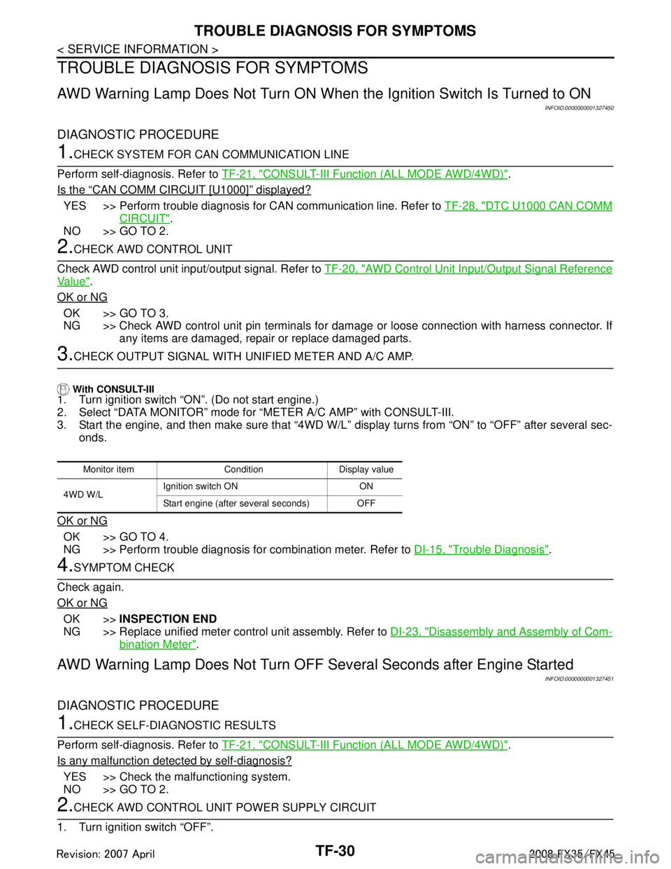
3.CHECK OUTPUT SIGNAL WITH UNIFIED METER AND A/C AMP.
With CONSULT-III
1. Turn ignition switch “ON”. (Do not start engine.)
2. Select “DATA MONITOR” mode for “METER A/C AMP” with CONSULT-III.
3. Start the engine, and then make sure that “4WD W/L” display turns from “ON” to “OFF” after several sec-
onds.
OK or NG
OK >> GO TO 4.
NG >> Perform trouble diagnosis for combination meter. Refer to DI-15, "
Trouble Diagnosis".
4.SYMPTOM CHECK
Check again.
OK or NG
OK >> INSPECTION END
NG >> Replace unified meter control unit assembly. Refer to DI-23, "
Disassembly and Assembly of Com-
bination Meter".
AWD Warning Lamp Does Not Turn OFF Several Seconds after Engine Started
INFOID:0000000001327451
DIAGNOSTIC PROCEDURE
1.CHECK SELF-DIAGNOSTIC RESULTS
Perform self-diagnosis. Refer to TF-21, "
CONSULT-III Function (ALL MODE AWD/4WD)".
Is any malfunction detec ted by self-diagnosis?
YES >> Check the malfunctioning system.
NO >> GO TO 2.
2.CHECK AWD CONTROL UNIT POWER SUPPLY CIRCUIT
1. Turn ignition switch “OFF”.
Monitor item Condition Display value
4WD W/L Ignition switch ON ON
Start engine (after several seconds) OFF
3AA93ABC3ACD3AC03ACA3AC03AC63AC53A913A773A893A873A873A8E3A773A983AC73AC93AC03AC3
3A893A873A873A8F3A773A9D3AAF3A8A3A8C3A863A9D3AAF3A8B3A8C
Page 3817 of 3924
TROUBLE DIAGNOSIS FOR SYMPTOMSTF-31
< SERVICE INFORMATION >
CEF
G H
I
J
K L
M A
B
TF
N
O P
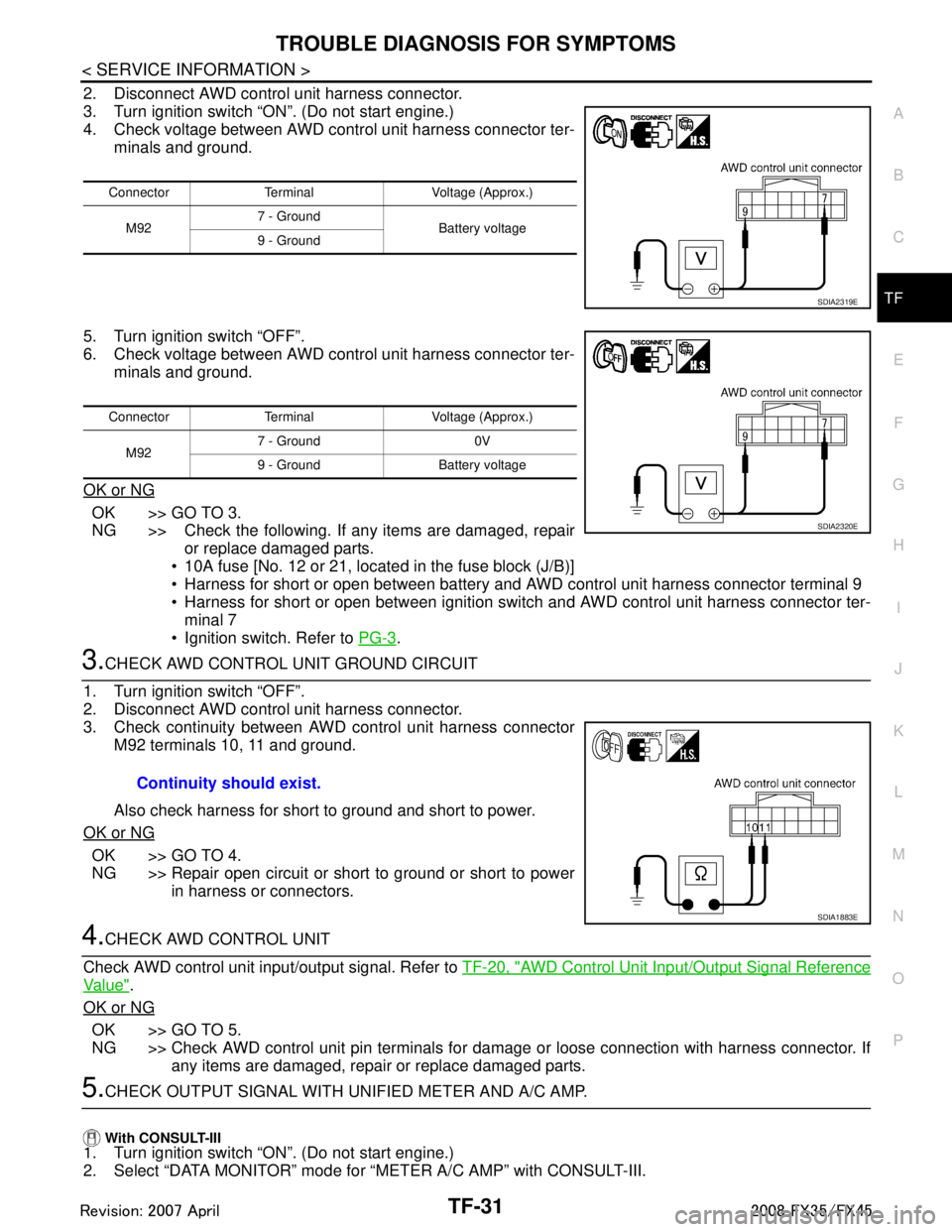
2. Disconnect AWD control unit harness connector.
3. Turn ignition switch “ON”. (Do not start engine.)
4. Check voltage between AWD control unit harness connector ter- minals and ground.
5. Turn ignition switch “OFF”.
6. Check voltage between AWD control unit harness connector ter- minals and ground.
OK or NG
OK >> GO TO 3.
NG >> Check the following. If any items are damaged, repair or replace damaged parts.
10A fuse [No. 12 or 21, located in the fuse block (J/B)]
Harness for short or open between battery and AWD control unit harness connector terminal 9
Harness for short or open between ignition switch and AWD control unit harness connector ter- minal 7
Ignition switch. Refer to PG-3
.
3.CHECK AWD CONTROL UNIT GROUND CIRCUIT
1. Turn ignition switch “OFF”.
2. Disconnect AWD control unit harness connector.
3. Check continuity between AWD control unit harness connector M92 terminals 10, 11 and ground.
Also check harness for short to ground and short to power.
OK or NG
OK >> GO TO 4.
NG >> Repair open circuit or short to ground or short to power in harness or connectors.
4.CHECK AWD CONTROL UNIT
Check AWD control unit input/output signal. Refer to TF-20, "
AWD Control Unit Input/Output Signal Reference
Va l u e".
OK or NG
OK >> GO TO 5.
NG >> Check AWD control unit pin terminals for damage or loose connection with harness connector. If any items are damaged, repair or replace damaged parts.
5.CHECK OUTPUT SIGNAL WITH UNIFIED METER AND A/C AMP.
With CONSULT-III
1. Turn ignition switch “ON”. (Do not start engine.)
2. Select “DATA MONITOR” mode for “METER A/C AMP” with CONSULT-III.
Connector Terminal Voltage (Approx.)
M92 7 - Ground
Battery voltage
9 - Ground
SDIA2319E
Connector Terminal Voltage (Approx.)
M92 7 - Ground 0V
9 - Ground Battery voltage
SDIA2320E
Continuity should exist.
SDIA1883E
3AA93ABC3ACD3AC03ACA3AC03AC63AC53A913A773A893A873A873A8E3A773A983AC73AC93AC03AC3
3A893A873A873A8F3A773A9D3AAF3A8A3A8C3A863A9D3AAF3A8B3A8C
Page 3818 of 3924
TF-32
< SERVICE INFORMATION >
TROUBLE DIAGNOSIS FOR SYMPTOMS
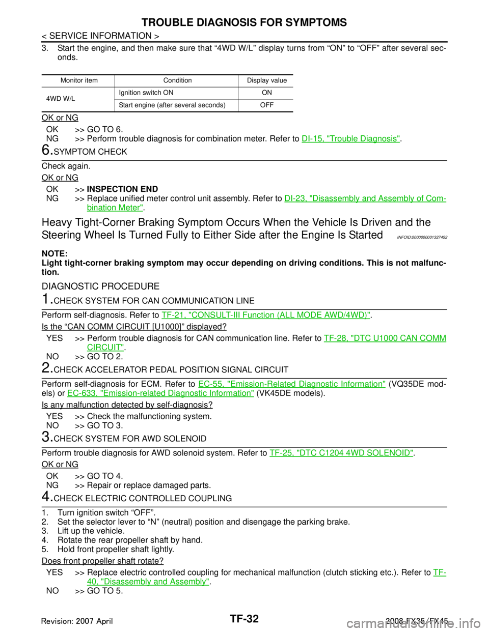
3. Start the engine, and then make sure that “4WD W/L” display turns from “ON” to “OFF” after several sec-
onds.
OK or NG
OK >> GO TO 6.
NG >> Perform trouble diagnosis for combination meter. Refer to DI-15, "
Trouble Diagnosis".
6.SYMPTOM CHECK
Check again.
OK or NG
OK >> INSPECTION END
NG >> Replace unified meter control unit assembly. Refer to DI-23, "
Disassembly and Assembly of Com-
bination Meter".
Heavy Tight-Corner Braking Symptom Occurs When the Vehicle Is Driven and the
Steering Wheel Is Turned Fu lly to Either Side after the Engine Is Started
INFOID:0000000001327452
NOTE:
Light tight-corner braking symptom may occur depending on driving conditions. This is not malfunc-
tion.
DIAGNOSTIC PROCEDURE
1.CHECK SYSTEM FOR CAN COMMUNICATION LINE
Perform self-diagnosis. Refer to TF-21, "
CONSULT-III Function (ALL MODE AWD/4WD)".
Is the
“CAN COMM CIRCUIT [U1000]” displayed?
YES >> Perform trouble diagnosis for CAN communication line. Refer to TF-28, "DTC U1000 CAN COMM
CIRCUIT".
NO >> GO TO 2.
2.CHECK ACCELERATOR PEDAL POSITION SIGNAL CIRCUIT
Perform self-diagnosis for ECM. Refer to EC-55, "
Emission-Related Diagnostic Information" (VQ35DE mod-
els) or EC-633, "
Emission-related Diagnostic Information" (VK45DE models).
Is any malfunction detec ted by self-diagnosis?
YES >> Check the malfunctioning system.
NO >> GO TO 3.
3.CHECK SYSTEM FOR AWD SOLENOID
Perform trouble diagnosis for AWD solenoid system. Refer to TF-25, "
DTC C1204 4WD SOLENOID".
OK or NG
OK >> GO TO 4.
NG >> Repair or replace damaged parts.
4.CHECK ELECTRIC CONTROLLED COUPLING
1. Turn ignition switch “OFF”.
2. Set the selector lever to “N” (neutral) position and disengage the parking brake.
3. Lift up the vehicle.
4. Rotate the rear propeller shaft by hand.
5. Hold front propeller shaft lightly.
Does front propeller shaft rotate?
YES >> Replace electric controlled coupling for mec hanical malfunction (clutch sticking etc.). Refer to TF-
40, "Disassembly and Assembly".
NO >> GO TO 5.
Monitor item Condition Display value
4WD W/L Ignition switch ON ON
Start engine (after several seconds) OFF
3AA93ABC3ACD3AC03ACA3AC03AC63AC53A913A773A893A873A873A8E3A773A983AC73AC93AC03AC3
3A893A873A873A8F3A773A9D3AAF3A8A3A8C3A863A9D3AAF3A8B3A8C
Page 3820 of 3924
TF-34
< SERVICE INFORMATION >
TROUBLE DIAGNOSIS FOR SYMPTOMS
DIAGNOSTIC PROCEDURE
1.CHECK TIRE
Check the following.
Tire pressure
Wear condition
Longitudinal tire size (There is no difference between longitudinal tires.)
OK or NG
OK >> GO TO 2.
NG >> Drive at vehicle speed of 20 km/h (12 MPH) or more for 5 seconds or more after repairing or replacing damaged parts. (Initialize improper size tire information.)
2.CHECK INPUT SIGNAL OF TIRE DIAMETER
With CONSULT-III
1. Start engine.
2. Drive at 20 km/h (12 MPH) or more for approx. 200 seconds.
3. Select “DATA MONITOR” mode for “ALL MODE AWD/4WD” with CONSULT-III.
4. Check monitor “DIS-TIRE MONI”.
Display of
“DIS-TIRE MONI”
“0-4mm”>> INSPECTION END
Except for “0-4mm”>>GO TO 3.
3.CHECK AWD CONTROL UNIT
Check AWD control unit input/output signal. Refer to TF-20, "
AWD Control Unit Input/Output Signal Reference
Va l u e".
OK or NG
OK >> GO TO 4.
NG >> Check AWD control unit pin terminals for dam age or loose connection with harness connector. If
any items are damaged, repair or replace damaged parts.
4.SYMPTOM CHECK
Check again.
OK or NG
OK >> INSPECTION END
NG >> Replace AWD control unit.
3AA93ABC3ACD3AC03ACA3AC03AC63AC53A913A773A893A873A873A8E3A773A983AC73AC93AC03AC3
3A893A873A873A8F3A773A9D3AAF3A8A3A8C3A863A9D3AAF3A8B3A8C
Page 3848 of 3924
WT-8
< SERVICE INFORMATION >
ROAD WHEEL TIRE ASSEMBLY
ROAD WHEEL TIRE ASSEMBLY
Balancing Wheels (Bonding Weight Type)INFOID:0000000001327574
REMOVAL
Using releasing agent, remove double-faced adhesive tape from the road wheel.
CAUTION:
Be careful not to scratch th e road wheel during removal.
After removing double-faced adhesive tape, wi pe clean traces of releasing agent from the road
wheel.
WHEEL BALANCE ADJUSTMENT
If a tire balance machine has adhesion balance weight mode settings and drive-in weight mode setting,
select and adjust a drive-in weight mode suitable for road wheels.
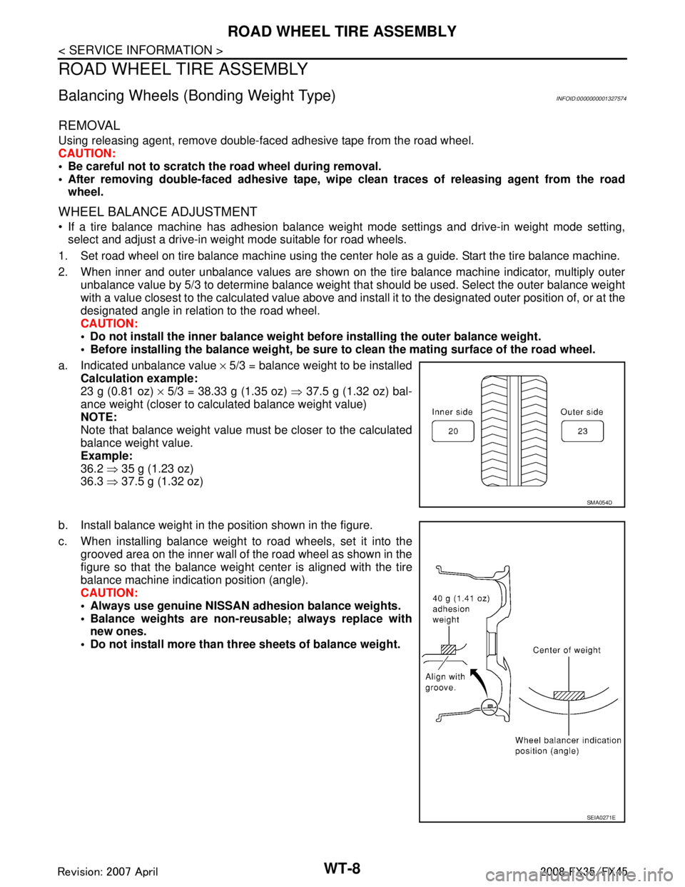
1. Set road wheel on tire balance machine using the center hole as a guide. Start the tire balance machine.
2. When inner and outer unbalance values are shown on the tire balance machine indicator, multiply outer unbalance value by 5/3 to determine balance weight t hat should be used. Select the outer balance weight
with a value closest to the calculated value above and inst all it to the designated outer position of, or at the
designated angle in relation to the road wheel.
CAUTION:
Do not install the inner balance weight before installing the outer balance weight.
Before installing the balance weight, be sure to clean the mating surface of the road wheel.
a. Indicated unbalance value × 5/3 = balance weight to be installed
Calculation example:
23 g (0.81 oz) × 5/3 = 38.33 g (1.35 oz) ⇒ 37.5 g (1.32 oz) bal-
ance weight (closer to calculated balance weight value)
NOTE:
Note that balance weight value must be closer to the calculated
balance weight value.
Example:
36.2 ⇒ 35 g (1.23 oz)
36.3 ⇒ 37.5 g (1.32 oz)
b. Install balance weight in the position shown in the figure.
c. When installing balance weight to road wheels, set it into the grooved area on the inner wall of the road wheel as shown in the
figure so that the balance weight center is aligned with the tire
balance machine indication position (angle).
CAUTION:
Always use genuine NISSAN adhesion balance weights.
Balance weights are non-reusable; always replace with new ones.
Do not install more than three sheets of balance weight.
SMA054D
SEIA0271E
:
Page 3849 of 3924
ROAD WHEEL TIRE ASSEMBLYWT-9
< SERVICE INFORMATION >
C
DF
G H
I
J
K L
M A
B
WT
N
O P
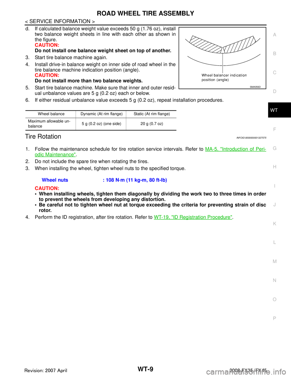
d. If calculated balance weight value exceeds 50 g (1.76 oz), install two balance weight sheets in line with each other as shown in
the figure.
CAUTION:
Do not install one balance weig ht sheet on top of another.
3. Start tire balance machine again.
4. Install drive-in balance weight on inner side of road wheel in the tire balance machine indication position (angle).
CAUTION:
Do not install more than two balance weights.
5. Start tire balance machine. Make sure that inner and outer resid- ual unbalance values are 5 g (0.2 oz) each or below.
6. If either residual unbalance value exceeds 5 g (0.2 oz), repeat installation procedures.
Tire RotationINFOID:0000000001327575
1. Follow the maintenance schedule for tire rotation service intervals. Refer to MA-5, "Introduction of Peri-
odic Maintenance".
2. Do not include the spare tire when rotating the tires.
3. When installing the wheel, tighten wheel nuts to the specified torque.
CAUTION:
When installing wheels, tighten th em diagonally by dividing the work two to three times in order
to prevent the wheels from developing any distortion.
Be careful not to tighten wheel nut at torque exceeding the criteria for preventing strain of disc
rotor.
4. Perform the ID registration, after tire rotation. Refer to WT-19, "
ID Registration Procedure".
Wheel balance Dynamic (At rim flange) Static (At rim flange)
Maximum allowable un-
balance 5 g (0.2 oz) (one side) 20 g (0.7 oz)
SMA056D
Wheel nuts : 108 N·m (11 kg-m, 80 ft-lb)
3AA93ABC3ACD3AC03ACA3AC03AC63AC53A913A773A893A873A873A8E3A773A983AC73AC93AC03AC3
3A893A873A873A8F3A773A9D3AAF3A8A3A8C3A863A9D3AAF3A8B3A8C
Page 3858 of 3924
WT-18
< SERVICE INFORMATION >
TROUBLE DIAGNOSES
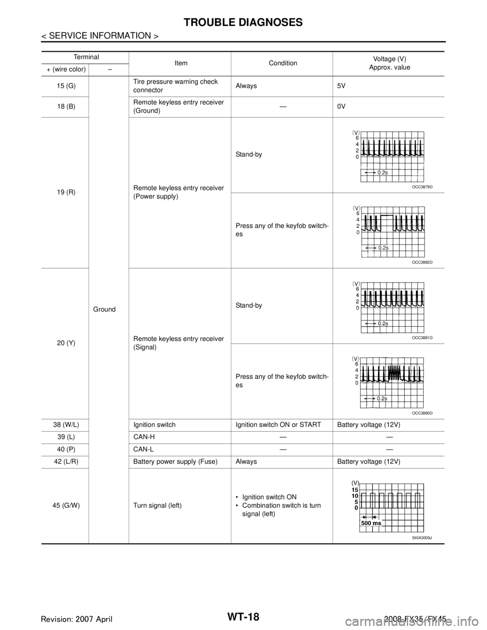
Te r m i n a lItem Condition Voltage (V)
Approx. value
+ (wire color) –
15 (G)
Ground Tire pressure
warning check
connector Always 5V
18 (B) Remote keyless entry receiver
(Ground) —0V
19 (R) Remote keyless entry receiver
(Power supply) Stand-by
Press any of the keyfob switch-
es
20 (Y) Remote keyless entry receiver
(Signal) Stand-by
Press any of the keyfob switch-
es
38 (W/L) Ignition switch Ignition switch ON or START Battery voltage (12V) 39 (L) CAN-H — —
40 (P) CAN-L — —
42 (L/R) Battery power supply (Fuse) Always Battery voltage (12V)
45 (G/W) Turn signal (left) Ignition switch ON
Combination switch is turn
signal (left)
OCC3879D
OCC3882D
OCC3881D
OCC3880D
SKIA3009J
3AA93ABC3ACD3AC03ACA3AC03AC63AC53A913A773A893A873A873A8E3A773A983AC73AC93AC03AC3
3A893A873A873A8F3A773A9D3AAF3A8A3A8C3A863A9D3AAF3A8B3A8C
Page 3860 of 3924
WT-20
< SERVICE INFORMATION >
TROUBLE DIAGNOSES
4. Inflate all tires to proper pressure. Refer to WT-35, "Tire".
Transmitter Wake Up OperationINFOID:0000000001327583
W I T H A C T I VAT I O N T O O L
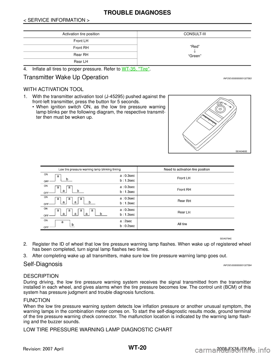
1. With the transmitter activation tool (J-45295) pushed against the
front-left transmitter, press the button for 5 seconds.
When ignition switch ON, as the low tire pressure warninglamp blinks per the following diagram, the respective transmit-
ter then must be woken up.
2. Register the ID of wheel that low tire pressure warning lamp flashes. When wake up of registered wheel
has been completed, turn signal lamp flashes two times.
3. After completing wake up all transmitters, make sure low tire pressure warning lamp goes out.
Self-DiagnosisINFOID:0000000001327584
DESCRIPTION
During driving, the low tire pressure warning syste m receives the signal transmitted from the transmitter
installed in each wheel, and gives alarms when the tire pressure becomes low. The control unit (BCM) of this
system has pressure judgment and trouble diagnosis functions.
FUNCTION
When the low tire pressure warning system detects low inflation pressure or another unusual symptom, the
warning lamps in the combination meter comes on. To start the self-diagnostic results mode, ground terminal
of the tire pressure warning check connector. The malf unction location is indicated by the warning lamp flash-
ing and the buzzer sounds.
LOW TIRE PRESSURE WARNING LAMP DIAGNOSTIC CHART
Activation tire position CONSULT-III
Front LH “Red”↓
“Green”
Front RH
Rear RHRear LH
SEIA0460E
SEIA0794E
3AA93ABC3ACD3AC03ACA3AC03AC63AC53A913A773A893A873A873A8E3A773A983AC73AC93AC03AC3
3A893A873A873A8F3A773A9D3AAF3A8A3A8C3A863A9D3AAF3A8B3A8C