2008 INFINITI FX35 no start
[x] Cancel search: no startPage 3798 of 3924
TF-12
< SERVICE INFORMATION >
AWD SYSTEM
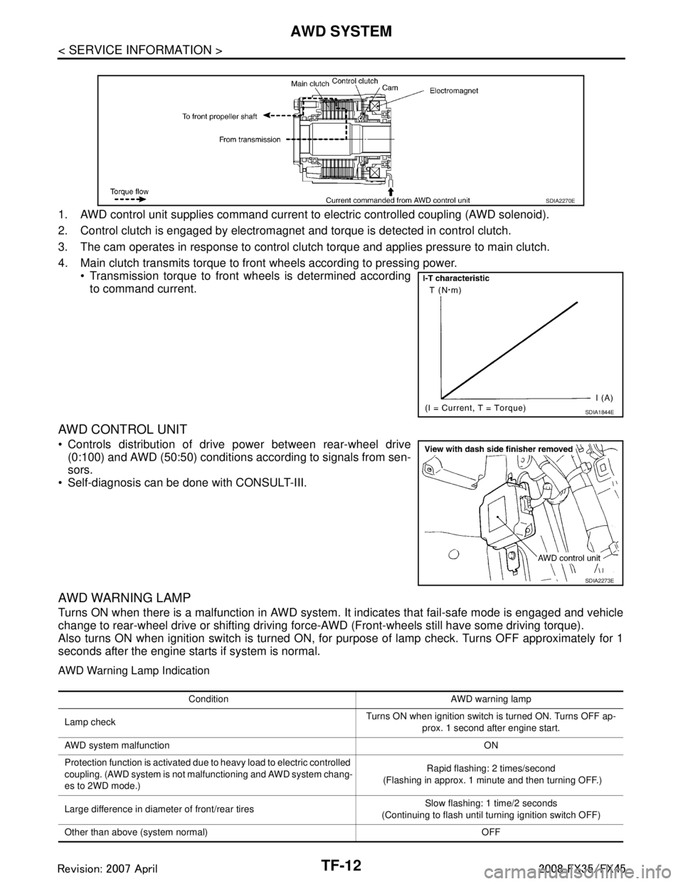
1. AWD control unit supplies command current to electric controlled coupling (AWD solenoid).
2. Control clutch is engaged by electromagnet and torque is detected in control clutch.
3. The cam operates in response to control clutch torque and applies pressure to main clutch.
4. Main clutch transmits torque to front wheels according to pressing power. Transmission torque to front wheels is determined accordingto command current.
AWD CONTROL UNIT
Controls distribution of drive power between rear-wheel drive(0:100) and AWD (50:50) conditions according to signals from sen-
sors.
Self-diagnosis can be done with CONSULT-III.
AWD WARNING LAMP
Turns ON when there is a malfunction in AWD system. It indicates that fail-safe mode is engaged and vehicle
change to rear-wheel drive or shifting driving force- AWD (Front-wheels still have some driving torque).
Also turns ON when ignition switch is turned ON, for purpose of lamp check. Turns OFF approximately for 1
seconds after the engine starts if system is normal.
AWD Warning Lamp Indication
SDIA2270E
SDIA1844E
SDIA2273E
Condition AWD warning lamp
Lamp check Turns ON when ignition switch is turned ON. Turns OFF ap-
prox. 1 second after engine start.
AWD system malfunction ON
Protection function is activated due to heavy load to electric controlled
coupling. (AWD system is not malfunctioning and AWD system chang-
es to 2WD mode.) Rapid flashing: 2 times/second
(Flashing in approx. 1 minute and then turning OFF.)
Large difference in diameter of front/rear tires Slow flashing: 1 time/2 seconds
(Continuing to flash until turning ignition switch OFF)
Other than above (system normal) OFF
3AA93ABC3ACD3AC03ACA3AC03AC63AC53A913A773A893A873A873A8E3A773A983AC73AC93AC03AC3
3A893A873A873A8F3A773A9D3AAF3A8A3A8C3A863A9D3AAF3A8B3A8C
Page 3806 of 3924
TF-20
< SERVICE INFORMATION >
TROUBLE DIAGNOSIS
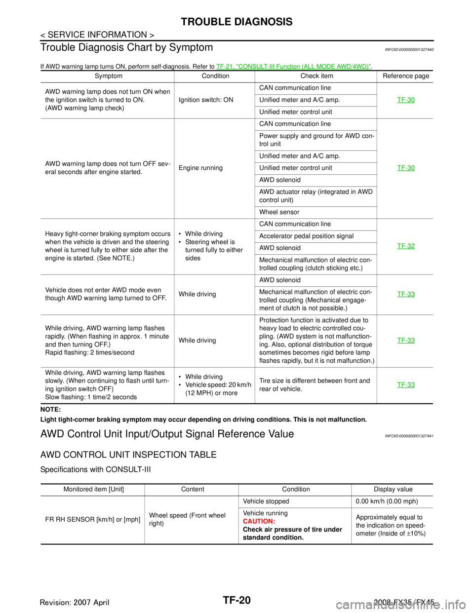
Trouble Diagnosis Chart by Symptom
INFOID:0000000001327440
If AWD warning lamp turns ON, perform self-diagnosis. Refer to TF-21, "CONSULT-III Function (ALL MODE AWD/4WD)".
NOTE:
Light tight-corner braking symptom may occur depending on driving conditions. This is not malfunction.
AWD Control Unit Input/Output Signal Reference ValueINFOID:0000000001327441
AWD CONTROL UNIT INSPECTION TABLE
Specifications with CONSULT-III
Symptom Condition Check item Reference page
AWD warning lamp does not turn ON when
the ignition switch is turned to ON.
(AWD warning lamp check) Ignition switch: ONCAN communication line
TF-30
Unified meter and A/C amp.
Unified meter control unit
AWD warning lamp does not turn OFF sev-
eral seconds after engine started. Engine runningCAN communication line
TF-30
Power supply and ground for AWD con-
trol unit
Unified meter and A/C amp.
Unified meter control unit
AWD solenoid
AWD actuator relay (integrated in AWD
control unit)
Wheel sensor
Heavy tight-corner braking symptom occurs
when the vehicle is driven and the steering
wheel is turned fully to either side after the
engine is started. (See NOTE.) While driving
Steering wheel is
turned fully to either
sides CAN communication line
TF-32
Accelerator pedal position signal
AWD solenoid
Mechanical malfunction of electric con-
trolled coupling (clutch sticking etc.)
Vehicle does not enter AWD mode even
though AWD warning lamp turned to OFF. While drivingAWD solenoid
TF-33
Mechanical malfunction of electric con-
trolled coupling (Mechanical engage-
ment of clutch is not possible.)
While driving, AWD warning lamp flashes
rapidly. (When flashing in approx. 1 minute
and then turning OFF.)
Rapid flashing: 2 times/second While drivingProtection function is activated due to
heavy load to electric controlled cou-
pling. (AWD system is not malfunction-
ing. Also, optional distribution of torque
sometimes becomes rigid before lamp
flashes rapidly, but it is not malfunction.) TF-33
While driving, AWD warning lamp flashes
slowly. (When continuing to flash until turn-
ing ignition switch OFF)
Slow flashing: 1 time/2 seconds While driving
Vehicle speed: 20 km/h
(12 MPH) or more Tire size is different between front and
rear of vehicle.
TF-33
Monitored item [Unit] Content Condition Display value
FR RH SENSOR [km/h] or [mph] Wheel speed (Front wheel
right)Vehicle stopped 0.00 km/h (0.00 mph)
Vehicle running
CAUTION:
Check air pressure of tire under
standard condition.
Approximately equal to
the indication on speed-
ometer (Inside of
±10%)
3AA93ABC3ACD3AC03ACA3AC03AC63AC53A913A773A893A873A873A8E3A773A983AC73AC93AC03AC3
3A893A873A873A8F3A773A9D3AAF3A8A3A8C3A863A9D3AAF3A8B3A8C
Page 3808 of 3924
TF-22
< SERVICE INFORMATION >
TROUBLE DIAGNOSIS
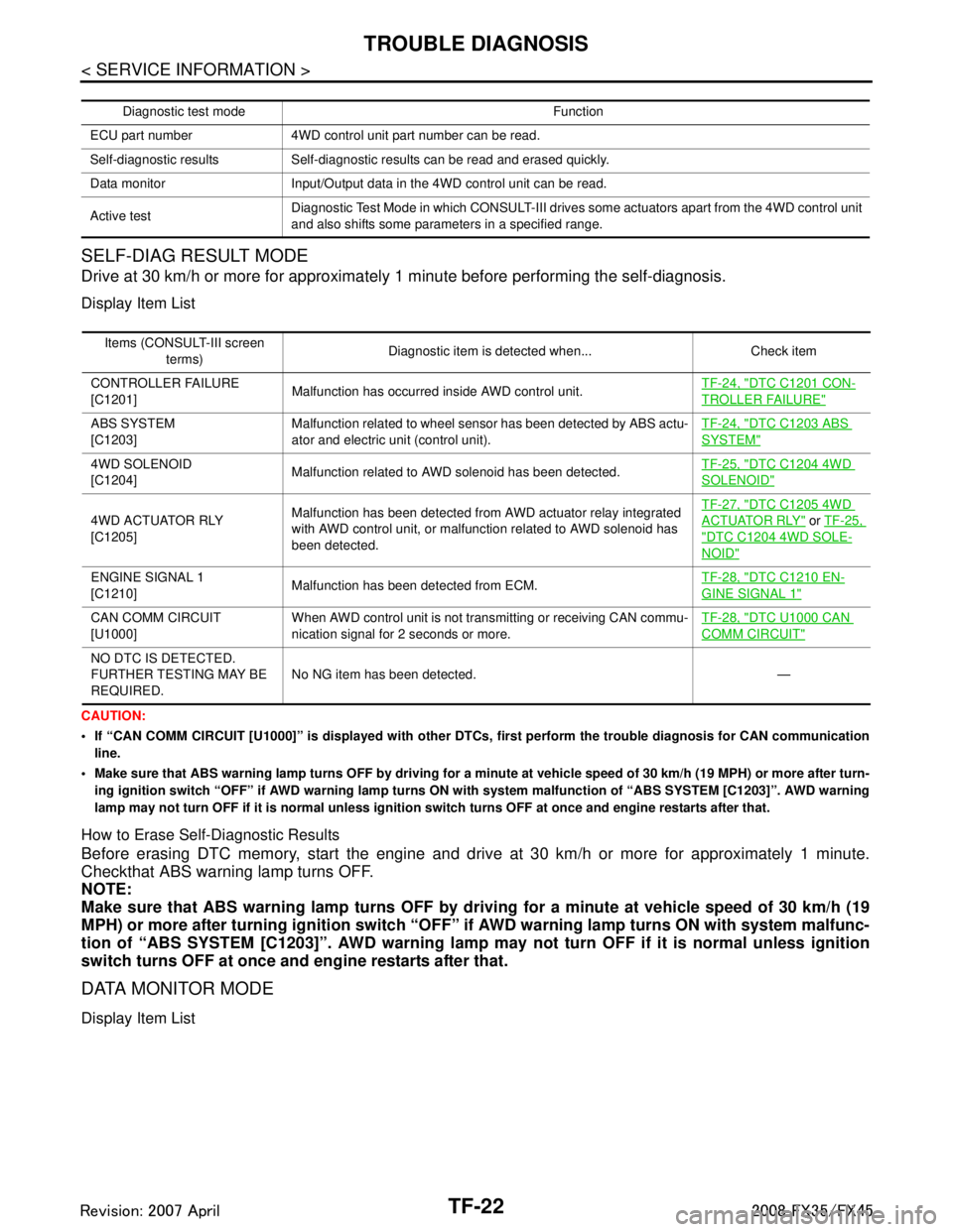
SELF-DIAG RESULT MODE
Drive at 30 km/h or more for approximately 1 minute before performing the self-diagnosis.
Display Item List
CAUTION:
If “CAN COMM CIRCUIT [U1000]” is displayed with other DTCs, first perform the trouble diagnosis for CAN communication
line.
Make sure that ABS warning lamp turns OFF by driving for a minute at vehicle speed of 30 km/h (19 MPH) or more after turn- ing ignition switch “OFF” if AWD warning lamp turns ON with system malfunction of “ABS SYSTEM [C1203]”. AWD warning
lamp may not turn OFF if it is normal unless ignition switch turns OFF at once and engine restarts after that.
How to Erase Self-Diagnostic Results
Before erasing DTC memory, start the engine and drive at 30 km/h or more for approximately 1 minute.
Checkthat ABS warning lamp turns OFF.
NOTE:
Make sure that ABS warning lamp turns OFF by driv ing for a minute at vehicle speed of 30 km/h (19
MPH) or more after turning ignition switch “OFF ” if AWD warning lamp turns ON with system malfunc-
tion of “ABS SYSTE M [C1203]”. AWD warning lamp may not turn OFF if it is normal unless ignition
switch turns OFF at once and engine restarts after that.
DATA MONITOR MODE
Display Item List
Diagnostic test mode Function
ECU part number 4WD control unit part number can be read.
Self-diagnostic results Self-diagnostic results can be read and erased quickly.
Data monitor Input/Output data in the 4WD control unit can be read.
Active test Diagnostic Test Mode in which CONSULT-III drives some actuators apart from the 4WD control unit
and also shifts some parameters in a specified range.
Items (CONSULT-III screen
terms) Diagnostic item is detected when... Check item
CONTROLLER FAILURE
[C1201] Malfunction has occurred inside AWD control unit. TF-24, "
DTC C1201 CON-
TROLLER FAILURE"
ABS SYSTEM
[C1203]Malfunction related to wheel sensor
has been detected by ABS actu-
ator and electric unit (control unit). TF-24, "DTC C1203 ABS
SYSTEM"
4WD SOLENOID
[C1204]
Malfunction related to AWD solenoid has been detected.
TF-25, "DTC C1204 4WD
SOLENOID"
4WD ACTUATOR RLY
[C1205]Malfunction has been detected from AWD actuator relay integrated
with AWD control unit, or malfunction related to AWD solenoid has
been detected. TF-27, "
DTC C1205 4WD
ACTUATOR RLY" or
TF-25,
"DTC C1204 4WD SOLE-
NOID"
ENGINE SIGNAL 1
[C1210] Malfunction has been detected from ECM. TF-28, "DTC C1210 EN-
GINE SIGNAL 1"
CAN COMM CIRCUIT
[U1000]When AWD control unit is not transmitting or receiving CAN commu-
nication signal for 2 seconds or more. TF-28, "DTC U1000 CAN
COMM CIRCUIT"
NO DTC IS DETECTED.
FURTHER TESTING MAY BE
REQUIRED.
No NG item has been detected. —
3AA93ABC3ACD3AC03ACA3AC03AC63AC53A913A773A893A873A873A8E3A773A983AC73AC93AC03AC3
3A893A873A873A8F3A773A9D3AAF3A8A3A8C3A863A9D3AAF3A8B3A8C
Page 3810 of 3924
TF-24
< SERVICE INFORMATION >
TROUBLE DIAGNOSIS FOR SYSTEM
TROUBLE DIAGNOSIS FOR SYSTEM
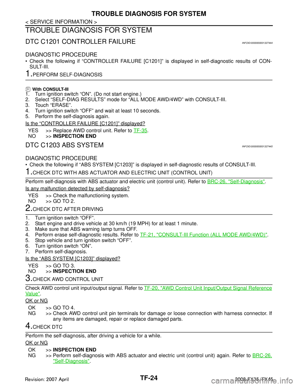
DTC C1201 CONTROLLER FAILUREINFOID:0000000001327444
DIAGNOSTIC PROCEDURE
Check the following if “CONTROLLER FAILURE [C1201]” is displayed in self-diagnostic results of CON-SULT-III.
1.PERFORM SELF-DIAGNOSIS
With CONSULT-III1. Turn ignition switch “ON”. (Do not start engine.)
2. Select “SELF-DIAG RESULTS” mode fo r “ALL MODE AWD/4WD” with CONSULT-III.
3. Touch “ERASE”.
4. Turn ignition switch “OFF” and wait at least 10 seconds.
5. Perform the self-diagnosis again.
Is the
“CONTROLLER FAILURE [C1201]” displayed?
YES >> Replace AWD control unit. Refer to TF-35.
NO >> INSPECTION END
DTC C1203 ABS SYSTEMINFOID:0000000001327445
DIAGNOSTIC PROCEDURE
Check the following if “ABS SYSTEM [C1203]” is disp layed in self-diagnostic results of CONSULT-III.
1.CHECK DTC WITH ABS ACTUATOR AND ELECTRIC UNIT (CONTROL UNIT)
Perform self-diagnosis with ABS actuator and electric unit (control unit). Refer to BRC-26, "
Self-Diagnosis".
Is any malfunction detec ted by self-diagnosis?
YES >> Check the malfunctioning system.
NO >> GO TO 2.
2.CHECK DTC AFTER DRIVING
1. Turn ignition switch “OFF”.
2. Start engine and drive vehicle at 30 km/h (19 MPH) for at least 1 minute.
3. Make sure that ABS warning lamp turns OFF.
4. Perform erase self-diagnostic results. Refer to TF-21, "
CONSULT-III Function (ALL MODE AWD/4WD)".
5. Stop vehicle and turn ignition switch “OFF”.
6. Turn ignition switch “ON”.
7. Perform self-diagnosis.
Is the
“ABS SYSTEM [C1203]” displayed?
YES >> GO TO 3.
NO >> INSPECTION END
3.CHECK AWD CONTROL UNIT
Check AWD control unit input/output signal. Refer to TF-20, "
AWD Control Unit Input/Output Signal Reference
Va l u e".
OK or NG
OK >> GO TO 4.
NG >> Check AWD control unit pin terminals for dam age or loose connection with harness connector. If
any items are damaged, repair or replace damaged parts.
4.CHECK DTC
Perform the self-diagnosis, after driving a vehicle for a while.
OK or NG
OK >> INSPECTION END
NG >> Perform self-diagnosis with ABS actuator and electric unit (control unit) again. Refer to BRC-26,
"Self-Diagnosis".
3AA93ABC3ACD3AC03ACA3AC03AC63AC53A913A773A893A873A873A8E3A773A983AC73AC93AC03AC3
3A893A873A873A8F3A773A9D3AAF3A8A3A8C3A863A9D3AAF3A8B3A8C
Page 3811 of 3924
TROUBLE DIAGNOSIS FOR SYSTEMTF-25
< SERVICE INFORMATION >
CEF
G H
I
J
K L
M A
B
TF
N
O P
DTC C1204 4WD SOLENOIDINFOID:0000000001327446
CONSULT-III REFERENCE VALUE IN DATA MONITOR MODE
Data are reference value.
*: The values are changed by throttle opening and engine speed.
DIAGNOSTIC PROCEDURE
Check the following if “4WD SOLENOID [C1204]” is di splayed in self-diagnostic results of CONSULT-III.
1.CHECK AWD SOLENOID SIGNAL
With CONSULT-III
1. Start engine.
2. Select “DATA MONITOR” mode for “A LL MODE AWD/4WD” with CONSULT-III.
3. Read out the value of “ETS SOLENOID”.
*: The values are changed by throttle opening and engine speed.
OK or NG
OK >> GO TO 6.
NG >> GO TO 2.
2.CHECK POWER SUPPLY
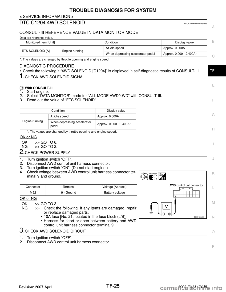
1. Turn ignition switch “OFF”.
2. Disconnect AWD control unit harness connector.
3. Turn ignition switch “ON”. (Do not start engine.)
4. Check voltage between AWD control unit harness connector ter- minal 9 and ground.
OK or NG
OK >> GO TO 3.
NG >> Check the following. If any items are damaged, repair or replace damaged parts.
10A fuse [No. 21, located in the fuse block (J/B)]
Harness for short or open between battery and AWD control unit harness connector terminal 9
3.CHECK AWD SOLENOID CIRCUIT
1. Turn ignition switch “OFF”.
2. Disconnect AWD control unit harness connector.
Monitored item [Unit] Condition Display value
ETS SOLENOID [A] Engine running At idle speed Approx. 0.000A
When depressing accelerator pedal Approx. 0.000 - 2.400A*
Condition Display value
Engine running At idle speed Approx. 0.000A
When depressing accelerator
pedal
Approx. 0.000 - 2.400A*
Connector Terminal Voltage (Approx.)
M92 9 - Ground Battery voltage
SDIA1884E
3AA93ABC3ACD3AC03ACA3AC03AC63AC53A913A773A893A873A873A8E3A773A983AC73AC93AC03AC3
3A893A873A873A8F3A773A9D3AAF3A8A3A8C3A863A9D3AAF3A8B3A8C
Page 3813 of 3924
TROUBLE DIAGNOSIS FOR SYSTEMTF-27
< SERVICE INFORMATION >
CEF
G H
I
J
K L
M A
B
TF
N
O P
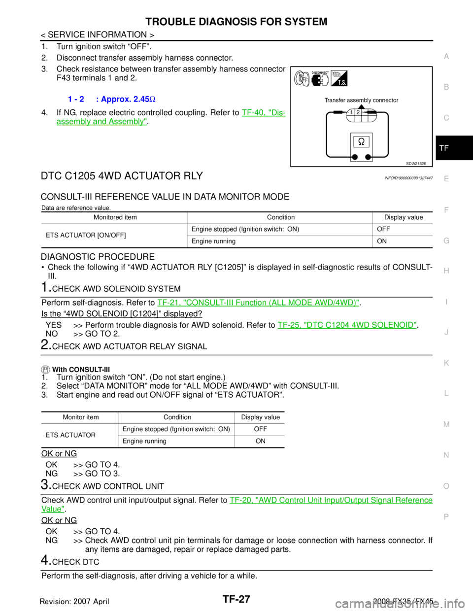
1. Turn ignition switch “OFF”.
2. Disconnect transfer assembly harness connector.
3. Check resistance between transfer assembly harness connector F43 terminals 1 and 2.
4. If NG, replace electric controlled coupling. Refer to TF-40, "
Dis-
assembly and Assembly".
DTC C1205 4WD ACTUATOR RLYINFOID:0000000001327447
CONSULT-III REFERENCE VALUE IN DATA MONITOR MODE
Data are reference value.
DIAGNOSTIC PROCEDURE
Check the following if “4WD ACTUATOR RLY [C1205]” is displayed in self-diagnostic results of CONSULT-
III.
1.CHECK AWD SOLENOID SYSTEM
Perform self-diagnosis. Refer to TF-21, "
CONSULT-III Function (ALL MODE AWD/4WD)".
Is the
“4WD SOLENOID [C1204]” displayed?
YES >> Perform trouble diagnosis for AWD solenoid. Refer to TF-25, "DTC C1204 4WD SOLENOID".
NO >> GO TO 2.
2.CHECK AWD ACTUATOR RELAY SIGNAL
With CONSULT-III
1. Turn ignition switch “ON”. (Do not start engine.)
2. Select “DATA MONITOR” mode for “A LL MODE AWD/4WD” with CONSULT-III.
3. Start engine and read out ON/OFF signal of “ETS ACTUATOR”.
OK or NG
OK >> GO TO 4.
NG >> GO TO 3.
3.CHECK AWD CONTROL UNIT
Check AWD control unit input/output signal. Refer to TF-20, "
AWD Control Unit Input/Output Signal Reference
Va l u e".
OK or NG
OK >> GO TO 4.
NG >> Check AWD control unit pin terminals for damage or loose connection with harness connector. If any items are damaged, repair or replace damaged parts.
4.CHECK DTC
Perform the self-diagnosis, after driving a vehicle for a while. 1 - 2 : Approx. 2.45
Ω
SDIA2162E
Monitored item Condition Display value
ETS ACTUATOR [ON/OFF] Engine stopped (Ignition switch: ON) OFF
Engine running ON
Monitor item Condition Display value
ETS ACTUATOR Engine stopped (Ignition switch: ON) OFF
Engine running ON
3AA93ABC3ACD3AC03ACA3AC03AC63AC53A913A773A893A873A873A8E3A773A983AC73AC93AC03AC3
3A893A873A873A8F3A773A9D3AAF3A8A3A8C3A863A9D3AAF3A8B3A8C
Page 3814 of 3924
TF-28
< SERVICE INFORMATION >
TROUBLE DIAGNOSIS FOR SYSTEM
OK or NG
OK >>INSPECTION END
NG >> Replace AWD control unit.
DTC C1210 ENGINE SIGNAL 1INFOID:0000000001327448
DIAGNOSTIC PROCEDURE
Check the following if “ECM SIGNAL 1 [C1210]” is di splayed in self-diagnostic results of CONSULT-III.
1.CHECK DTC WITH ECM
Perform self-diagnosis with ECM. Refer to EC-55, "
Emission-Related Diagnostic Information" (VQ engine
models) or EC-633, "
Emission-related Diagnostic Information" (VK engine models).
Is any malfunction detec ted by self-diagnosis?
YES >> Check the malfunctioning system.
NO >> GO TO 2.
2.CHECK AWD CONTROL UNIT
Check AWD control unit input/output signal. Refer to TF-20, "
AWD Control Unit Input/Output Signal Reference
Va l u e".
OK or NG
OK >> GO TO 3.
NG >> Check AWD control unit pin terminals for dam age or loose connection with harness connector. If
any items are damaged, repair or replace damaged parts.
3.CHECK DTC
Perform the self-diagnosis, after driving a vehicle for a while.
OK or NG
OK >> INSPECTION END
NG >> Perform self-diagnosis with ECM again. Refer to EC-55, "
Emission-Related Diagnostic Informa-
tion" (VQ engine models) or EC-633, "Emission-related Diagnostic Information" (VK engine mod-
els).
DTC U1000 CAN COMM CIRCUITINFOID:0000000001327449
DIAGNOSTIC PROCEDURE
Check the following if “CAN COMM CIRCUIT [U1000]” is detected in self-diagnostic results of CONSULT-III.
1.CHECK CAN COMMUNICATION CIRCUIT
With CONSULT-III
1. Turn ignition switch “ON” and start engine.
2. Select “SELF-DIAG RESULTS” mode for “ALL MODE AWD/4WD” with in CONSULT-III.
3. Perform the self-diagnosis.
Is the
“CAN COMM CIRCUIT [U1000]” displayed?
YES >> Print out CONSULT-III screen and go to LAN-43, "CAN System Specification Chart".
NO >> INSPECTION END
Power Supply Circuit for AWD Control UnitINFOID:0000000001327443
CONSULT-III REFERENCE VALUE IN DATA MONITOR MODE
Data are reference value.
DIAGNOSTIC PROCEDURE
1.CHECK POWER SUPPLY
1. Turn ignition switch “OFF”.
Monitored item [Unit] Condition Display value (Approx.)
BATTERY VOLT [V] Ignition switch: ON Battery voltage
3AA93ABC3ACD3AC03ACA3AC03AC63AC53A913A773A893A873A873A8E3A773A983AC73AC93AC03AC3
3A893A873A873A8F3A773A9D3AAF3A8A3A8C3A863A9D3AAF3A8B3A8C
Page 3815 of 3924
TROUBLE DIAGNOSIS FOR SYSTEMTF-29
< SERVICE INFORMATION >
CEF
G H
I
J
K L
M A
B
TF
N
O P
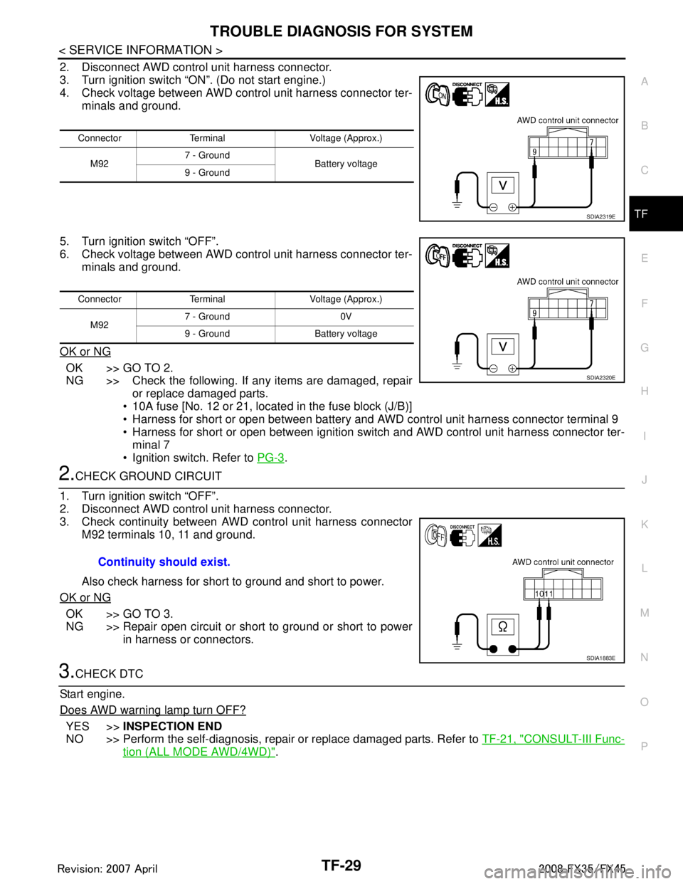
2. Disconnect AWD control unit harness connector.
3. Turn ignition switch “ON”. (Do not start engine.)
4. Check voltage between AWD control unit harness connector ter- minals and ground.
5. Turn ignition switch “OFF”.
6. Check voltage between AWD control unit harness connector ter- minals and ground.
OK or NG
OK >> GO TO 2.
NG >> Check the following. If any items are damaged, repair or replace damaged parts.
10A fuse [No. 12 or 21, located in the fuse block (J/B)]
Harness for short or open between battery and AWD control unit harness connector terminal 9
Harness for short or open between ignition switch and AWD control unit harness connector ter- minal 7
Ignition switch. Refer to PG-3
.
2.CHECK GROUND CIRCUIT
1. Turn ignition switch “OFF”.
2. Disconnect AWD control unit harness connector.
3. Check continuity between AWD control unit harness connector M92 terminals 10, 11 and ground.
Also check harness for short to ground and short to power.
OK or NG
OK >> GO TO 3.
NG >> Repair open circuit or short to ground or short to power in harness or connectors.
3.CHECK DTC
Start engine.
Does AWD warning lamp turn OFF?
YES >> INSPECTION END
NO >> Perform the self-diagnosis, repair or replace damaged parts. Refer to TF-21, "
CONSULT-III Func-
tion (ALL MODE AWD/4WD)".
Connector Terminal Voltage (Approx.)
M92 7 - Ground
Battery voltage
9 - Ground
SDIA2319E
Connector Terminal Voltage (Approx.)
M92 7 - Ground 0V
9 - Ground Battery voltage
SDIA2320E
Continuity should exist.
SDIA1883E
3AA93ABC3ACD3AC03ACA3AC03AC63AC53A913A773A893A873A873A8E3A773A983AC73AC93AC03AC3
3A893A873A873A8F3A773A9D3AAF3A8A3A8C3A863A9D3AAF3A8B3A8C