2008 INFINITI FX35 no start
[x] Cancel search: no startPage 3671 of 3924

SE-32
< SERVICE INFORMATION >
AUTOMATIC DRIVE POSITIONER
Terminal and Reference Value for BCM
INFOID:0000000001328103
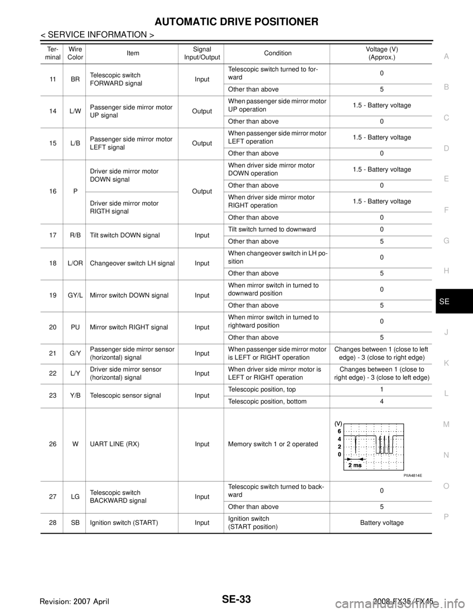
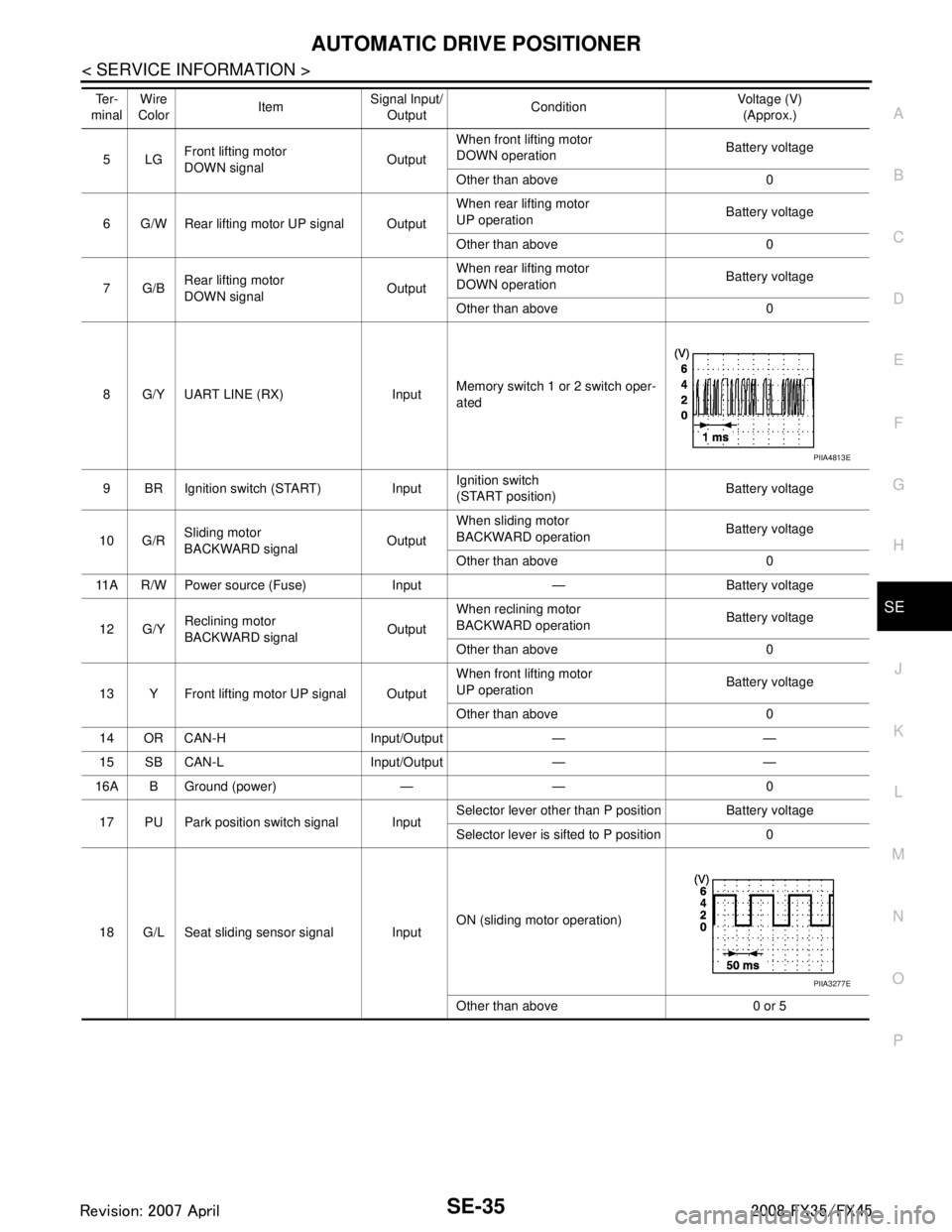
Terminal and Reference Value for Auto matic Drive Positioner Control UnitINFOID:0000000001328104
Te r -
minal Wire
Color Item Signal
Input/Output Condition Voltage (V)
(Approx.)
11 LG Ignition switch (ACC) Input Ignition switch
(ACC or ON position)
Battery voltage
37 B/W Key switch signal Input Key switch ON (key is inserted in
ignition key cylinder)
Battery voltage
Key switch OFF (key is removed
from ignition key cylinder) 0
38 W/L Ignition switch (ON) Input Ignition switch
(ON or START position)
Battery voltage
39 L CAN-H Input/Output — —
40 P CAN-L Input/Output — —
42 L/R Power source (Fuse) Input — Battery voltage
49 B Ground (signal) — — 0
52 B Ground (power) — — 0
55 G Power supply (Fusible link) Input — Battery voltage
62 W Front door switch
(driver side)
Output ON (Open)
→ OFF (Closed) 0 → Battery voltage
Te r -
minal Wire
Color Item Signal
Input/Output Condition Voltage (V)
(Approx.)
1 R Tilt switch UP signal Input Tilt switch turned to upward 0
Other than above 5
2 G/W Changeover switch RH signal Input When changeover switch in RH
position
0
Other than above 5
3 GY Mirror switch UP signal Input When mirror switch in turned to up-
ward position
0
Other than above 5
4 Y Mirror switch LEFT signal Input When mirror switch in turned to
leftward position
0
Other than above 5
5OR Passenger side mirror sensor
(vertical) signal Input
When passenger si
de mirror motor
is UP or DOWN operation Changes between 3 (close to
perk) - 1 (close to valley)
6P/L Driver side mirror sensor
(vertical) signal InputWhen driver side mirror motor is
UP or DOWN operation Changes between 3 (close to
perk) - 1 (close to valley)
7 Y/R Tilt sensor signal Input Tilt position, top 2
Tilt position, bottom 4
10 B UART LINE (TX) Output Memory switch 1 or 2 operated
PIIA4813E
3AA93ABC3ACD3AC03ACA3AC03AC63AC53A913A773A893A873A873A8E3A773A983AC73AC93AC03AC3
3A893A873A873A8F3A773A9D3AAF3A8A3A8C3A863A9D3AAF3A8B3A8C
Page 3672 of 3924
AUTOMATIC DRIVE POSITIONERSE-33
< SERVICE INFORMATION >
C
DE
F
G H
J
K L
M A
B
SE
N
O P
11 B R Telescopic switch
FORWARD signal
InputTelescopic switch turned to for-
ward
0
Other than above 5
14 L/W Passenger side
mirror motor
UP signal OutputWhen passenger si
de mirror motor
UP operation 1.5 - Battery voltage
Other than above 0
15 L/B Passenger side
mirror motor
LEFT signal OutputWhen passenger si
de mirror motor
LEFT operation 1.5 - Battery voltage
Other than above 0
16 P Driver side mirror motor
DOWN signal
OutputWhen driver side mirror motor
DOWN operation
1.5 - Battery voltage
Other than above 0
Driver side mirror motor
RIGTH signal When driver side mirror motor
RIGHT operation
1.5 - Battery voltage
Other than above 0
17 R/B Tilt switch DOWN signal Input Tilt switch turned to downward 0
Other than above 5
18 L/OR Changeover switch LH signal Input When changeover switch in LH po-
sition
0
Other than above 5
19 GY/L Mirror switch DOWN signal Input When mirror switch
in turned to
downward position 0
Other than above 5
20 PU Mirror switch RIGHT signal Input When mirror switch
in turned to
rightward position 0
Other than above 5
21 G/Y Passenger side
mirror sensor
(horizontal) signal InputWhen passenger si
de mirror motor
is LEFT or RIGHT operation Changes between 1 (close to left
edge) - 3 (close to right edge)
22 L/Y Driver side mirror sensor
(horizontal) signal
InputWhen driver side
mirror motor is
LEFT or RIGHT operation Changes between 1 (close to
right edge) - 3 (close to left edge)
23 Y/B Telescopic sensor signal Input Telescopic position, top 1
Telescopic position, bottom 4
26 W UART LINE (RX) Input Memory switch 1 or 2 operated
27 LG Telescopic switch
BACKWARD signal InputTelescopic switch turned to back-
ward
0
Other than above 5
28 SB Ignition switch (START) Input Ignition switch
(START position)
Battery voltage
Te r -
minal Wire
Color
Item Signal
Input/Output Condition Voltage (V)
(Approx.)
PIIA4814E
3AA93ABC3ACD3AC03ACA3AC03AC63AC53A913A773A893A873A873A8E3A773A983AC73AC93AC03AC3
3A893A873A873A8F3A773A9D3AAF3A8A3A8C3A863A9D3AAF3A8B3A8C
Page 3674 of 3924
AUTOMATIC DRIVE POSITIONERSE-35
< SERVICE INFORMATION >
C
DE
F
G H
J
K L
M A
B
SE
N
O P
5LG Front lifting motor
DOWN signal
OutputWhen front lifting motor
DOWN operation
Battery voltage
Other than above 0
6 G/W Rear lifting motor UP signal Output When rear lifting motor
UP operation
Battery voltage
Other than above 0
7G/B Rear lifting motor
DOWN signal OutputWhen rear lifting motor
DOWN operation
Battery voltage
Other than above 0
8 G/Y UART LINE (RX) Input Memory switch 1 or 2 switch oper-
ated
9 BR Ignition switch (START) Input Ignition switch
(START position)Battery voltage
10 G/R Sliding motor
BACKWARD signal
OutputWhen sliding motor
BACKWARD operation
Battery voltage
Other than above 0
11A R/W Power source (Fuse) Input — Battery voltage
12 G/Y Reclining motor
BACKWARD signal OutputWhen reclining motor
BACKWARD operation
Battery voltage
Other than above 0
13 Y Front lifting motor UP signal Output When front lifting motor
UP operation
Battery voltage
Other than above 0
14 OR CAN-H Input/Output — —
15 SB CAN-L Input/Output — —
16A B Ground (power) — — 0
17 PU Park position switch signal Input Selector lever other than P position Battery voltage
Selector lever is sifted to P position 0
18 G/L Seat sliding sensor signal Input ON (sliding motor operation)
Other than above 0 or 5
Te r -
minal Wire
Color ItemSignal Input/
Output Condition Voltage (V)
(Approx.)
PIIA4813E
PIIA3277E
3AA93ABC3ACD3AC03ACA3AC03AC63AC53A913A773A893A873A873A8E3A773A983AC73AC93AC03AC3
3A893A873A873A8F3A773A9D3AAF3A8A3A8C3A863A9D3AAF3A8B3A8C
Page 3678 of 3924
![INFINITI FX35 2008 Service Manual
AUTOMATIC DRIVE POSITIONERSE-39
< SERVICE INFORMATION >
C
DE
F
G H
J
K L
M A
B
SE
N
O P
Check 10A fuse [No.9, loca ted in fuse block (J/B)].
NOTE:
Refer to SE-16, "
Component Parts and Harness Con INFINITI FX35 2008 Service Manual
AUTOMATIC DRIVE POSITIONERSE-39
< SERVICE INFORMATION >
C
DE
F
G H
J
K L
M A
B
SE
N
O P
Check 10A fuse [No.9, loca ted in fuse block (J/B)].
NOTE:
Refer to SE-16, "
Component Parts and Harness Con](/manual-img/42/57017/w960_57017-3677.png)
AUTOMATIC DRIVE POSITIONERSE-39
< SERVICE INFORMATION >
C
DE
F
G H
J
K L
M A
B
SE
N
O P
Check 10A fuse [No.9, loca ted in fuse block (J/B)].
NOTE:
Refer to SE-16, "
Component Parts and Harness Connector Location".
OK or NG
OK >> GO TO 5.
NG >> If fuse is blown out, be sure to eliminate c ause of malfunction before installing new fuse. Refer to
SE-16, "
Component Parts and Harness Connector Location".
5.CHECK POWER SUPPLY CIRCUIT (DRIVER SEAT CONTROL UNIT)
1. Disconnect driver seat control unit connector.
2. Check voltage between driver seat control unit and ground.
OK or NG
OK >> GO TO 6.
NG >> Repair or replace harness between driver seat control unit and fuse block (J/B).
6.CHECK GROUND CIRCUIT (DRIVER SEAT CONTROL UNIT)
1. Turn ignition switch OFF.
2. Check continuity between the dr iver seat control unit connector
B152, B153 terminal16A, 61E and ground.
OK or NG
OK >> GO TO 7.
NG >> Repair or replace harness between driver seat control unit and ground.
7.CHECK POWER SUPPLY CIRCUIT (AUTOMAT IC DRIVE POSITIONER CONTROL UNIT)
1. Disconnect automatic drive positioner control unit connector.
2. Check voltage between automatic drive positioner control unit and ground.
OK or NG
OK >> GO TO 8.
NG >> Repair or replace harness between automatic drive positioner control unit and fuse block (J/B).
8.CHECK GROUND CIRCUIT (AUTOMATIC DRI VE POSITIONER CONTROL UNIT)
ConnectorTerminals (W
ire color)
Ignition
switch Voltage (V)
(Approx.)
(+) (–)
B152 9 (BR) GroundSTART
Battery voltage
B153 1A (R)
OFF
11 A ( R / W )
PIIA5085E
16A (B) – Ground : Continuity should exist.
61E (B/Y) – Ground : Continuity should exist.
PIIA5087E
Connector Terminals (W
ire color)
Ignition
switch Voltage (V)
(Approx.)
(+) (–)
M49 28 (SB) GroundSTART
Battery voltage
M50 34 (L/R)
OFF
39 (W/R)
PIIA5086E
3AA93ABC3ACD3AC03ACA3AC03AC63AC53A913A773A893A873A873A8E3A773A983AC73AC93AC03AC3
3A893A873A873A8F3A773A9D3AAF3A8A3A8C3A863A9D3AAF3A8B3A8C
Page 3681 of 3924
SE-42
< SERVICE INFORMATION >
AUTOMATIC DRIVE POSITIONER
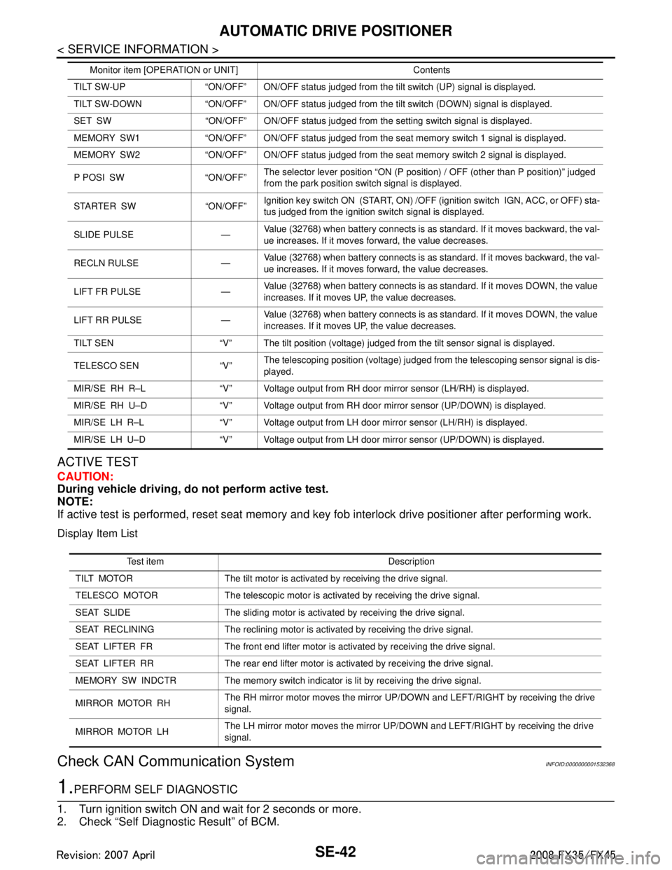
ACTIVE TEST
CAUTION:
During vehicle driving, do not perform active test.
NOTE:
If active test is performed, reset seat memory and key fob interlock drive positioner after performing work.
Display Item List
Check CAN Communication SystemINFOID:0000000001532368
1.PERFORM SELF DIAGNOSTIC
1. Turn ignition switch ON and wait for 2 seconds or more.
2. Check “Self Diagnostic Result” of BCM.
TILT SW-UP “ON/OFF” ON/OFF status judged from the tilt switch (UP) signal is displayed.
TILT SW-DOWN “ON/OFF” ON/OFF status judged from the tilt switch (DOWN) signal is displayed.
SET SW “ON/OFF” ON/OFF status judged from the setting switch signal is displayed.
MEMORY SW1 “ON/OFF” ON/OFF status judged from th e seat memory switch 1 signal is displayed.
MEMORY SW2 “ON/OFF” ON/OFF status judged from th e seat memory switch 2 signal is displayed.
P POSI SW “ON/OFF” The selector lever position “ON (P position) / OFF (other than P position)” judged
from the park position switch signal is displayed.
STARTER SW “ON/OFF” Ignition key switch ON (START, ON) /OFF (ignition switch IGN, ACC, or OFF) sta-
tus judged from the ignition switch signal is displayed.
SLIDE PULSE — Value (32768) when battery connects is as standard. If it moves backward, the val-
ue increases. If it moves forward, the value decreases.
RECLN RULSE — Value (32768) when battery connects is as standard. If it moves backward, the val-
ue increases. If it moves forward, the value decreases.
LIFT FR PULSE — Value (32768) when battery connects is as standard. If it moves DOWN, the value
increases. If it moves UP, the value decreases.
LIFT RR PULSE — Value (32768) when battery connects is as standard. If it moves DOWN, the value
increases. If it moves UP, the value decreases.
TILT SEN “V” The tilt position (voltage) judged from the tilt sensor signal is displayed.
TELESCO SEN “V” The telescoping position (voltage) judged from the telescoping sensor signal is dis-
played.
MIR/SE RH R–L “V” Voltage output from RH do or mirror sensor (LH/RH) is displayed.
MIR/SE RH U–D “V” Voltage output from RH door mirror sensor (UP/DOWN) is displayed.
MIR/SE LH R–L “V” Voltage output from LH door mirror sensor (LH/RH) is displayed.
MIR/SE LH U–D “V” Voltage output from LH door mirror sensor (UP/DOWN) is displayed. Monitor item [OPERAT
ION or UNIT] Contents
Test item Description
TILT MOTOR The tilt motor is activated by receiving the drive signal.
TELESCO MOTOR The telescopic motor is activated by receiving the drive signal.
SEAT SLIDE The sliding motor is activated by receiving the drive signal.
SEAT RECLINING The reclining motor is activated by receiving the drive signal.
SEAT LIFTER FR The front end lifter motor is activated by receiving the drive signal.
SEAT LIFTER RR The rear end lifter motor is activated by receiving the drive signal.
MEMORY SW INDCTR The memory sw itch indicator is lit by receivin g the drive signal.
MIRROR MOTOR RH The RH mirror motor moves the mirror UP/DOW
N and LEFT/RIGHT by receiving the drive
signal.
MIRROR MOTOR LH The LH mirror motor moves the mirror UP/DOW
N and LEFT/RIGHT by receiving the drive
signal.
3AA93ABC3ACD3AC03ACA3AC03AC63AC53A913A773A893A873A873A8E3A773A983AC73AC93AC03AC3
3A893A873A873A8F3A773A9D3AAF3A8A3A8C3A863A9D3AAF3A8B3A8C
Page 3746 of 3924
SUPPLEMENTAL RESTRAINT SYSTEM (SRS)SRS-9
< SERVICE INFORMATION >
C
DE
F
G
I
J
K L
M A
B
SRS
N
O P
SUPPLEMENTAL RESTRAINT SYSTEM (SRS)
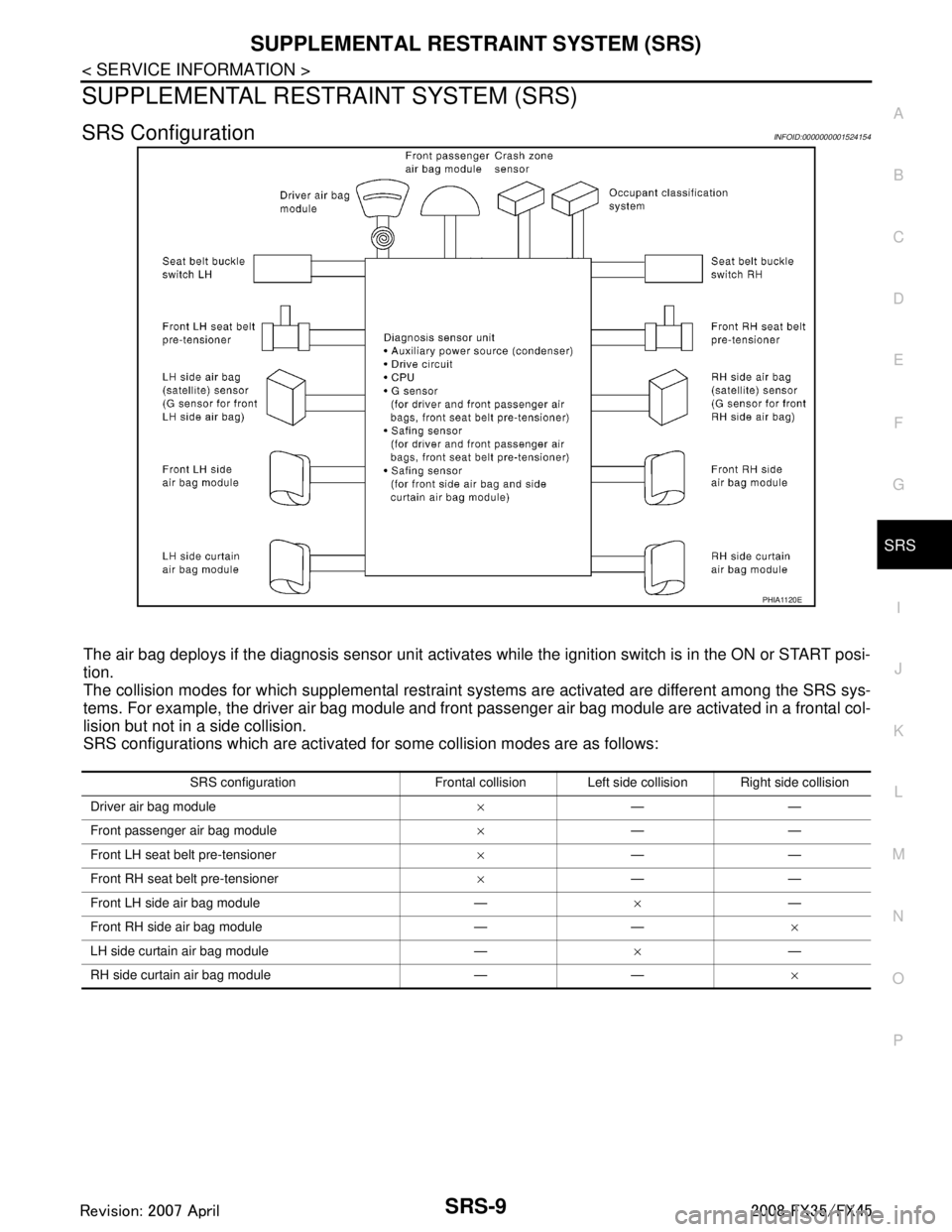
SRS ConfigurationINFOID:0000000001524154
The air bag deploys if the diagnosis sensor unit activates while the ignition switch is in the ON or START posi-
tion.
The collision modes for which supplemental restraint systems are activated are different among the SRS sys-
tems. For example, the driver air bag module and front passenger air bag module are activated in a frontal col-
lision but not in a side collision.
SRS configurations which are activated for some collision modes are as follows:
PHIA1120E
SRS configuration Frontal collision Left side collision Right side collision
Driver air bag module ×——
Front passenger air bag module ×——
Front LH seat belt pre-tensioner ×——
Front RH seat belt pre-tensioner ×——
Front LH side air bag module — ×—
Front RH side air bag module — — ×
LH side curtain air bag module — ×—
RH side curtain air bag module — — ×
3AA93ABC3ACD3AC03ACA3AC03AC63AC53A913A773A893A873A873A8E3A773A983AC73AC93AC03AC3
3A893A873A873A8F3A773A9D3AAF3A8A3A8C3A863A9D3AAF3A8B3A8C
Page 3787 of 3924

TF-1
DRIVELINE/AXLE
CEF
G H
I
J
K L
M
SECTION TF
A
B
TF
N
O P
CONTENTS
TRANSFER
SERVICE INFORMATION .. ..........................3
DTC INDEX ..................................................... .....3
C1201-C1210, U1000 ......................................... ......3
PRECAUTIONS ...................................................4
Precaution for Supplemental Restraint System
(SRS) "AIR BAG" and "SEAT BELT PRE-TEN-
SIONER" ............................................................. ......
4
Precaution .................................................................4
Service Notice or Precaution .....................................5
PREPARATION ...................................................6
Special Service Tool ........................................... ......6
Commercial Service Tool ..........................................7
NOISE, VIBRATION AND HARSHNESS
(NVH) TROUBLESHOOTING .............................
9
NVH Troubleshooting Chart ................................ ......9
TRANSFER FLUID .............................................10
Replacement ....................................................... ....10
Inspection ................................................................10
AWD SYSTEM ................................................ ....11
Power Transfer Diagram ..................................... ....11
System Description .................................................11
Schematic ...............................................................13
CAN Communication ...............................................13
TROUBLE DIAGNOSIS .....................................14
Fail-Safe Function ............................................... ....14
How to Perform Trouble Diagnosis .........................14
Location of Electrical Parts ......................................15
Circuit Diagram .......................................................16
Wiring Diagram - AWD - ..........................................17
Trouble Diagnosis Chart by Symptom ....................20
AWD Control Unit Input/Output Signal Reference
Value ................................................................... ....
20
CONSULT-III Function (ALL MODE AWD/4WD) ....21
TROUBLE DIAGNOSIS FOR SYSTEM .............24
DTC C1201 CONTROLLER FAILURE ................ ....24
DTC C1203 ABS SYSTEM ......................................24
DTC C1204 4WD SOLENOID ............................. ....25
DTC C1205 4WD ACTUATOR RLY ........................27
DTC C1210 ENGINE SIGNAL 1 ..............................28
DTC U1000 CAN COMM CIRCUIT .........................28
Power Supply Circuit for AWD Control Unit .............28
TROUBLE DIAGNOSIS FOR SYMPTOMS ......30
AWD Warning Lamp Does Not Turn ON When the
Ignition Switch Is Turned to ON ...............................
30
AWD Warning Lamp Does Not Turn OFF Several
Seconds after Engine Started ..................................
30
Heavy Tight-Corner Braking Symptom Occurs
When the Vehicle Is Driven and the Steering
Wheel Is Turned Fully to Either Side after the En-
gine Is Started .........................................................
32
Vehicle Does Not Enter AWD Mode Even Though
AWD Warning Lamp Turned to OFF .......................
33
While Driving, AWD Warning Lamp Flashes Rap-
idly (When Flashing in Approx. 1 Minute and Then
Turning OFF) ....................................................... ....
33
While Driving, AWD Warning Lamp Flashes Slow-
ly (When Continuing to Flash until Turning Ignition
Switch OFF) .............................................................
33
AWD CONTROL UNIT ......................................35
Removal and Installation .........................................35
FRONT OIL SEAL .............................................36
Removal and Installation .........................................36
REAR OIL SEAL ...............................................37
Removal and Installation .........................................37
AIR BREATHER HOSE ....................................39
Removal and Installation .........................................39
TRANSFER ASSEMBLY ..................................40
Removal and Installation .........................................40
Disassembly and Assembly .....................................40
3AA93ABC3ACD3AC03ACA3AC03AC63AC53A913A773A893A873A873A8E3A773A983AC73AC93AC03AC3
3A893A873A873A8F3A773A9D3AAF3A8A3A8C3A863A9D3AAF3A8B3A8C
Page 3797 of 3924
AWD SYSTEMTF-11
< SERVICE INFORMATION >
CEF
G H
I
J
K L
M A
B
TF
N
O P
AWD SYSTEM
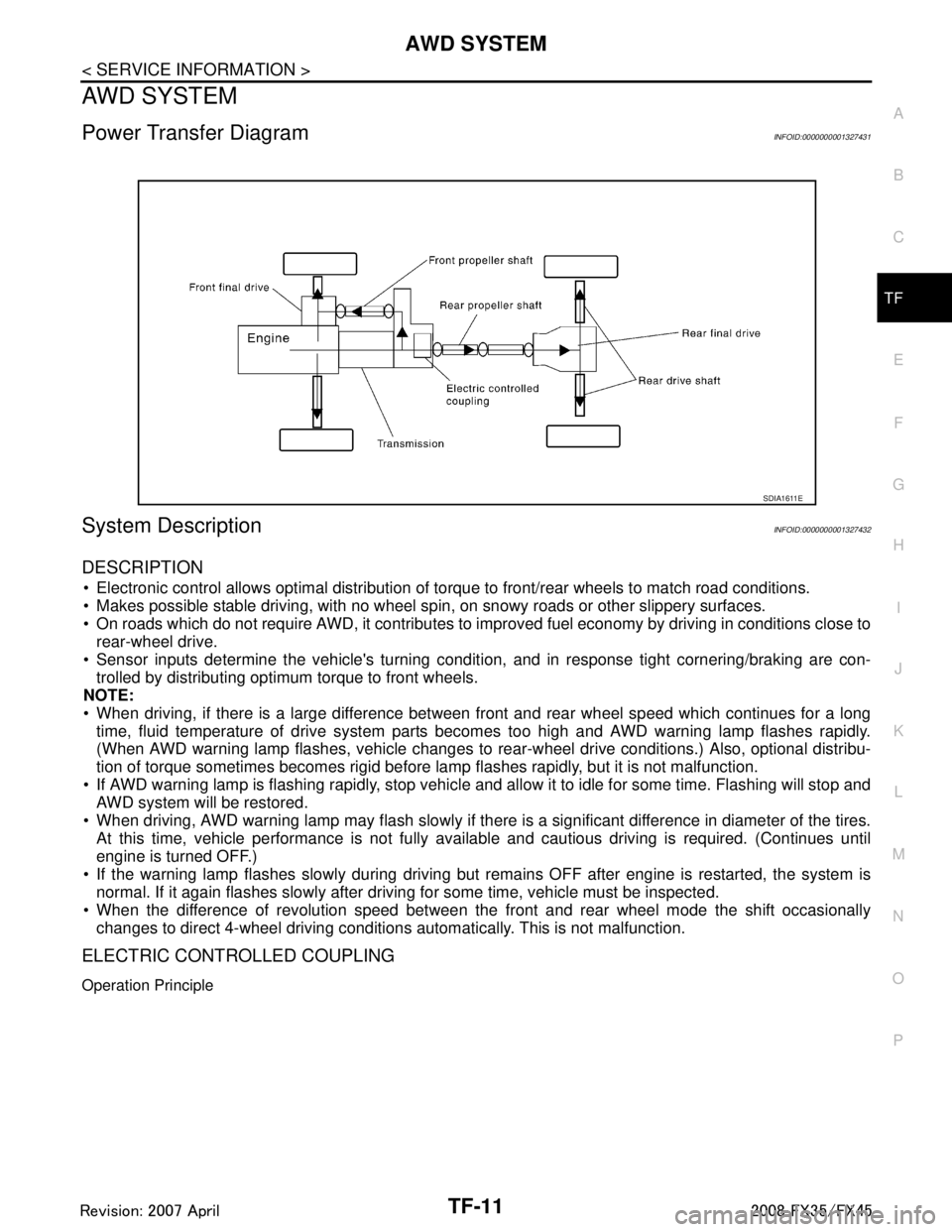
Power Transfer DiagramINFOID:0000000001327431
System DescriptionINFOID:0000000001327432
DESCRIPTION
Electronic control allows optimal distribution of torque to front/rear wheels to match road conditions.
Makes possible stable driving, with no wheel sp in, on snowy roads or other slippery surfaces.
On roads which do not require AWD, it contributes to improved fuel economy by driving in conditions close to
rear-wheel drive.
Sensor inputs determine the vehicle's turning conditi on, and in response tight cornering/braking are con-
trolled by distributing optimum torque to front wheels.
NOTE:
When driving, if there is a large difference between front and rear wheel speed which continues for a long
time, fluid temperature of drive system parts becom es too high and AWD warning lamp flashes rapidly.
(When AWD warning lamp flashes, vehicle changes to r ear-wheel drive conditions.) Also, optional distribu-
tion of torque sometimes becomes rigid before lamp flashes rapidly, but it is not malfunction.
If AWD warning lamp is flashing rapidly, stop vehicle and allow it to idle for some time. Flashing will stop and AWD system will be restored.
When driving, AWD warning lamp may flash slowly if ther e is a significant difference in diameter of the tires.
At this time, vehicle performance is not fully avail able and cautious driving is required. (Continues until
engine is turned OFF.)
If the warning lamp flashes slowly during driving but remains OFF after engine is restarted, the system is
normal. If it again flashes slowly after driving for some time, vehicle must be inspected.
When the difference of revolution speed between the front and rear wheel mode the shift occasionally
changes to direct 4-wheel driving conditions automatically. This is not malfunction.
ELECTRIC CONTROLLED COUPLING
Operation Principle
SDIA1611E
3AA93ABC3ACD3AC03ACA3AC03AC63AC53A913A773A893A873A873A8E3A773A983AC73AC93AC03AC3
3A893A873A873A8F3A773A9D3AAF3A8A3A8C3A863A9D3AAF3A8B3A8C