2008 INFINITI FX35 towing
[x] Cancel search: towingPage 2483 of 3924
EI-46
< SERVICE INFORMATION >
LUGGAGE FLOOR TRIM
Removal and Installation
INFOID:0000000001529413
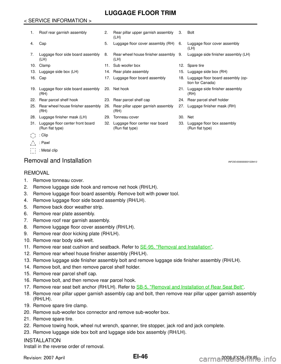
REMOVAL
1. Remove tonneau cover.
2. Remove luggage side hook and remove net hook (RH/LH).
3. Remove luggage floor board assembly. Remove bolt with power tool.
4. Remove luggage floor side board assembly (RH/LH).
5. Remove back door weather strip.
6. Remove rear plate assembly.
7. Remove roof rear garnish assembly.
8. Remove luggage floor cover assembly (RH/LH).
9. Remove rear door kicking plate (RH/LH).
10. Remove rear body side welt.
11. Remove rear seat cushion and seatback. Refer to SE-95, "
Removal and Installation".
12. Remove rear wheel house finisher assembly (RH/LH).
13. Remove luggage side finisher assembly bolt and remove luggage side finisher assembly (RH/LH).
14. Remove bolt, and then remove parcel shelf holder.
15. Remove rear parcel shelf cap.
16. Remove bolt, and then remove rear parcel hook.
17. Remove rear seat belt anchor (RH/LH). Refer to SB-5, "
Removal and Installation of Rear Seat Belt".
18. Remove rear pillar upper garnish assembly cap and bolt, then remove rear pillar upper garnish assembly (RH/LH).
19. Remove spare tire clamp.
20. Remove sub-woofer box connector and remove sub-woofer box.
21. Remove spare tire.
22. Remove towing hook, wheel nut wrench, spanner, tire stopper, jack rod and jack complete.
23. Remove luggage side box bolt and luggage side box assembly (RH/LH).
INSTALLATION
Install in the reverse order of removal.
1. Roof rear garnish assembly 2. Rear pillar upper garnish assembly (LH)3. Bolt
4. Cap 5. Luggage floor cover assembly (RH) 6. Luggage floor cover assembly (LH)
7. Luggage floor side board assembly (LH) 8. Rear wheel house finisher assembly
(LH) 9. Luggage side finisher assembly (LH)
10. Clamp 11. Sub woofer box 12. Spare tire
13. Luggage side box (LH) 14. Rear plate assembly 15. Luggage side box (RH)
16. Cap 17. Luggage floor board assembly 18. Luggage floor board assembly (op- tion for Canada)
19. Luggage floor side board assembly (RH) 20. Net hook 21. Luggage side finisher assembly
(RH)
22. Rear parcel shelf hook 23. Rear parcel shelf cap 24. Rear parcel shelf holder
25. Rear wheel house finisher assembly (RH) 26. Rear pillar upper garnish assembly
(RH) 27. Luggage finisher mask (RH)
28. Luggage finisher mask (LH) 29. Tonneau cover 30. Net
31. Luggage floor center front board (Run flat type) 32. Luggage floor center rear board
(Run flat type) 33. Luggage floor box assembly
(Run flat type)
: Clip
: Pawl
: Metal clip
3AA93ABC3ACD3AC03ACA3AC03AC63AC53A913A773A893A873A873A8E3A773A983AC73AC93AC03AC3
3A893A873A873A8F3A773A9D3AAF3A8A3A8C3A863A9D3AAF3A8B3A8C
Page 2863 of 3924
GI-1
GENERAL INFORMATION
C
DE
F
G H
I
J
K L
M B
GI
SECTION GI
N
O P
CONTENTS
GENERAL INFORMATION
SERVICE INFORMATION .. ..........................2
PRECAUTIONS .............................................. .....2
Description .......................................................... ......2
Precaution for Supplemental Restraint System
(SRS) "AIR BAG" and "SEAT BELT PRE-TEN-
SIONER" ...................................................................
2
Precaution Necessary for Steering Wheel Rota-
tion After Battery Disconnect .....................................
2
Precaution for Procedure without Cowl Top Cover ......3
General Precaution ...................................................3
Precaution for Three Way Catalyst ...........................4
Precaution for Fuel (Unleaded Premium Gasoline
Recommended) .........................................................
5
Precaution for Fuel (Unleaded Premium Gasoline
Required) ..................................................................
5
Precaution for Multiport Fuel Injection System or
Engine Control System .............................................
5
Precaution for Hoses .................................................5
Precaution for Engine Oils ........................................6
Precaution for the Environment .................................7
Precaution for Air Conditioning .................................7
HOW TO USE THIS MANUAL ............................8
Description .......................................................... ......8
Terms ........................................................................8
Units ..........................................................................8
Contents ....................................................................8
Component ................................................................8
How to Follow Trouble Diagnosis ..............................9
How to Read Wiring Diagram ..................................13
Abbreviations ..........................................................20
SERVICE INFORMATION FOR ELECTRICAL
INCIDENT ...........................................................
22
How to Check Terminal ....................................... ....22
How to Perform Efficient Diagnosis for an Electri-
cal Incident .......................................................... ....
25
Control Units and Electrical Parts ............................32
CONSULT-III/GST CHECKING SYSTEM .........34
Description ...............................................................34
CONSULT-III Function and System Application*1 ....34
CONSULT-III/GST Data Link Connector (DLC)
Circuit ......................................................................
35
Wiring Diagram - CONSULT-III/GST CHECKING
SYSTEM - ................................................................
36
LIFTING POINT .................................................37
Commercial Service Tool ........................................37
Garage Jack and Safety Stand ................................37
2-Pole Lift ................................................................38
Board-On Lift ...........................................................38
TOW TRUCK TOWING .....................................40
Tow Truck Towing ...................................................40
Vehicle Recovery (Freeing a Stuck Vehicle) ...........41
TIGHTENING TORQUE OF STANDARD
BOLTS ...............................................................
43
Tightening Torque Table .........................................43
RECOMMENDED CHEMICAL PRODUCTS
AND SEALANTS ...............................................
44
Recommended Chemical Product and Sealant .......44
IDENTIFICATION INFORMATION ....................45
Model Variation ........................................................45
Dimensions ..............................................................47
Wheels & Tires ........................................................47
TERMINOLOGY ................................................48
SAE J1930 Terminology List ...................................48
3AA93ABC3ACD3AC03ACA3AC03AC63AC53A913A773A893A873A873A8E3A773A983AC73AC93AC03AC3
3A893A873A873A8F3A773A9D3AAF3A8A3A8C3A863A9D3AAF3A8B3A8C
Page 2902 of 3924
GI-40
< SERVICE INFORMATION >
TOW TRUCK TOWING
TOW TRUCK TOWING
Tow Truck TowingINFOID:0000000001325684
CAUTION:
All applicable state or Provincial (in Canada) laws and local laws regarding the towing operation
must be obeyed.
It is necessary to use proper towi ng equipment to avoid possible damage to the vehicle during tow-
ing operation. To wing is in accordance with Towing Procedure Manual at dealer.
Always attach safety chains before towing.
When towing, make sure that the transmission, steering system and powertrain are in good order. If
any unit is damaged, dollies must be used.
Never tow an automatic transmission model from the rear (that is backward) with four wheels on the
ground. This may cause serious and exp ensive damage to the transmission.
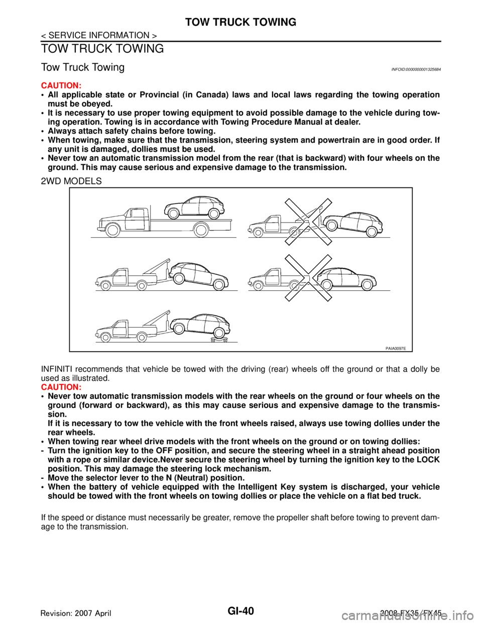
2WD MODELS
INFINITI recommends that vehicle be towed with the dr iving (rear) wheels off the ground or that a dolly be
used as illustrated.
CAUTION:
Never tow automatic transmission models with the r ear wheels on the ground or four wheels on the
ground (forward or backward), as this may cause serious and expensive damage to the transmis-
sion.
If it is necessary to tow the vehicle with the fron t wheels raised, always use towing dollies under the
rear wheels.
When towing rear wheel drive mo dels with the front wheels on the ground or on towing dollies:
- Turn the ignition key to the OFF position, and secure the steering wh eel in a straight ahead position
with a rope or similar device.Never secure the st eering wheel by turning the ignition key to the LOCK
position. This may damage the steering lock mechanism.
- Move the selector lever to the N (Neutral) position.
When the battery of vehicle equipped with the Intelligent Key system is discharged, your vehicle
should be towed with the front wh eels on towing dollies or place the vehicle on a flat bed truck.
If the speed or distance must necessarily be greater, re move the propeller shaft before towing to prevent dam-
age to the transmission.
PAIA0097E
3AA93ABC3ACD3AC03ACA3AC03AC63AC53A913A773A893A873A873A8E3A773A983AC73AC93AC03AC3
3A893A873A873A8F3A773A9D3AAF3A8A3A8C3A863A9D3AAF3A8B3A8C
Page 2903 of 3924
TOW TRUCK TOWINGGI-41
< SERVICE INFORMATION >
C
DE
F
G H
I
J
K L
M B
GI
N
O P
AWD MODELS
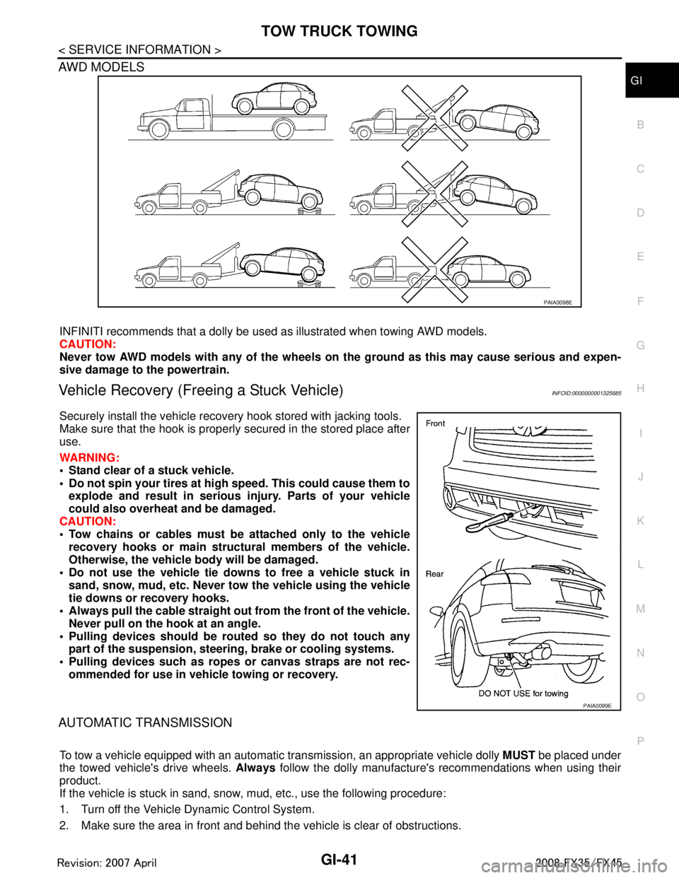
INFINITI recommends that a dolly be used as illustrated when towing AWD models.
CAUTION:
Never tow AWD models with any of the wheels on the ground as this may cause serious and expen-
sive damage to the powertrain.
Vehicle Recovery (Freeing a Stuck Vehicle)INFOID:0000000001325685
Securely install the vehicle recovery hook stored with jacking tools.
Make sure that the hook is properly secured in the stored place after
use.
WARNING:
Stand clear of a stuck vehicle.
Do not spin your tires at high speed. This could cause them to
explode and result in serious injury. Parts of your vehicle
could also overheat and be damaged.
CAUTION:
Tow chains or cables must be attached only to the vehicle recovery hooks or main struct ural members of the vehicle.
Otherwise, the vehicle body will be damaged.
Do not use the vehicle tie downs to free a vehicle stuck in
sand, snow, mud, etc. Never to w the vehicle using the vehicle
tie downs or recovery hooks.
Always pull the cable straight out from the front of the vehicle.
Never pull on the hook at an angle.
Pulling devices should be rout ed so they do not touch any
part of the suspension, steer ing, brake or cooling systems.
Pulling devices such as ropes or canvas straps are not rec- ommended for use in vehicle towing or recovery.
AUTOMATIC TRANSMISSION
To tow a vehicle equipped with an automatic tr ansmission, an appropriate vehicle dolly MUST be placed under
the towed vehicle's drive wheels. Always follow the dolly manufacture's recommendations when using their
product.
If the vehicle is stuck in sand, snow , mud, etc., use the following procedure:
1. Turn off the Vehicle Dynamic Control System.
2. Make sure the area in front and behind the vehicle is clear of obstructions.
PAIA0098E
PAIA0099E
3AA93ABC3ACD3AC03ACA3AC03AC63AC53A913A773A893A873A873A8E3A773A983AC73AC93AC03AC3
3A893A873A873A8F3A773A9D3AAF3A8A3A8C3A863A9D3AAF3A8B3A8C
Page 2904 of 3924

GI-42
< SERVICE INFORMATION >
TOW TRUCK TOWING
3. Turn the steering wheel right and left to clear an area around the front tires.
4. Slowly rock the vehicle forward and backward.Shift back and forth between R (reverse) and D (drive).
Apply the accelerator as little as possible to maintain the rocking motion.
Release the accelerator pedal before shifting between R and D.
Do not spin the tires above 35 mph (55 km/h).
5. If the vehicle can not be freed after a few tries, cont act a professional towing service to remove the vehi-
cle.
3AA93ABC3ACD3AC03ACA3AC03AC63AC53A913A773A893A873A873A8E3A773A983AC73AC93AC03AC3
3A893A873A873A8F3A773A9D3AAF3A8A3A8C3A863A9D3AAF3A8B3A8C
Page 3322 of 3924
PERIODIC MAINTENANCEMA-5
< SERVICE INFORMATION >
C
DE
F
G H
I
J
K
M A
B
MA
N
O P
PERIODIC MAINTENANCE
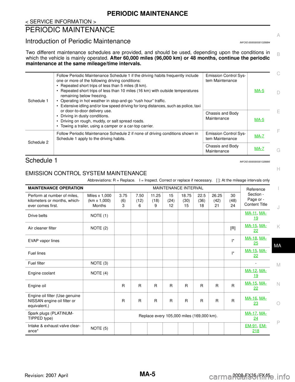
Introduction of Periodic MaintenanceINFOID:0000000001328894
Two different maintenance schedules are provi ded, and should be used, depending upon the conditions in
which the vehicle is mainly operated. After 60,000 miles (96,000 km) or 48 months, continue the periodic
maintenance at the same mileage/time intervals.
Schedule 1INFOID:0000000001328895
EMISSION CONTROL SYSTEM MAINTENANCE
Abbreviations: R = Replace. I = Inspect. Correct or r eplace if necessary. [ ]: At the mileage intervals only
Schedule 1Follow Periodic Maintenance Schedule 1 if the driving habits frequently include
one or more of the following driving conditions:
Repeated short trips of less than 5 miles (8 km).
Repeated short trips of less than 10 miles (16 km) with outside temperatures
remaining below freezing.
Operating in hot weather in stop-and-go “rush hour” traffic.
Extensive idling and/or low speed driving for long distances, such as police, taxi or door-to-door delivery use.
Driving in dusty conditions.
Driving on rough, muddy, or salt spread roads.
Towing a trailer, using a camper or a car-top carrier. Emission Control Sys-
tem Maintenance
MA-5
Chassis and Body
MaintenanceMA-5
Schedule 2Follow Periodic Maintenance Schedule 2 if none of driving conditions shown in
Schedule 1 apply to the driving habits.
Emission Control Sys-
tem Maintenance
MA-7Chassis and Body
Maintenance
MA-7
MAINTENANCE OPERATION
MAINTENANCE INTERVAL
Reference
Section -
Page or -
Content Title
Perform at number of miles,
kilometers or months, which-
ever comes first. Miles x 1,000
(km x 1,000) Months 3.75
(6)3 7.50
(12) 6 11 . 2 5
(18) 9 15
(24) 12 18.75
(30)15 22.5
(36) 18 26.25
(42)21 30
(48) 24
Drive belts NOTE (1) MA-11
,
MA-
19
Air cleaner filter NOTE (2) [R] MA-15,
MA-
22
EVAP vapor lines I*MA-18,
MA-
25
Fuel lines I*MA-15,
MA-
22
Fuel filter NOTE (3) -
Engine coolant NOTE (4) MA-12
,
MA-
19
Engine oil R R R R R R R R MA-15,
MA-
22
Engine oil filter (Use genuine
NISSAN engine oil filter or
equivalent.) R R RRRRR R
MA-16,
MA-
23
Spark plugs (PLATINUM-
TIPPED type) Replace every 105,000 miles (169,000 km).
MA-17,
MA-
24
Intake & exhaust valve clear-
ance* NOTE (5) EM-91,
EM-
218
3AA93ABC3ACD3AC03ACA3AC03AC63AC53A913A773A893A873A873A8E3A773A983AC73AC93AC03AC3
3A893A873A873A8F3A773A9D3AAF3A8A3A8C3A863A9D3AAF3A8B3A8C
Page 3324 of 3924
PERIODIC MAINTENANCEMA-7
< SERVICE INFORMATION >
C
DE
F
G H
I
J
K
M A
B
MA
N
O P
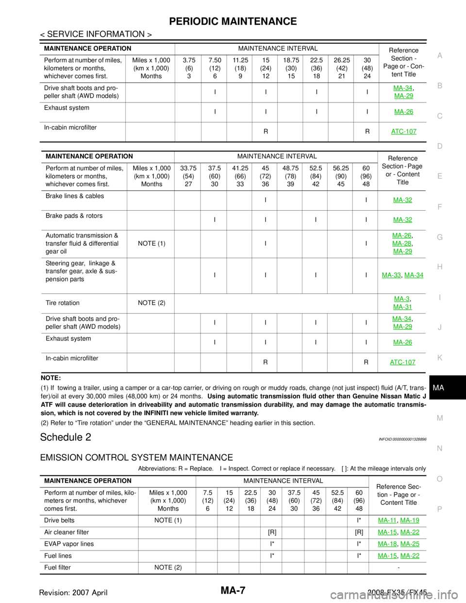
NOTE:
(1) If towing a trailer, using a camper or a car-top carrier, or driving on rough or muddy roads, change (not just inspect) fl uid (A/T, trans-
fer)/oil at every 30,000 miles (48,000 km) or 24 months. Using automatic transmission fluid other than Genuine Nissan Matic J
ATF will cause deterioration in driveability and automatic transmission durability, and may damage the automatic transmis-
sion, which is not covered by the INFINITI new vehicle limited warranty.
(2) Refer to “Tire rotation” under the “GENERAL MAINTENANCE” heading earlier in this section.
Schedule 2INFOID:0000000001328896
EMISSION COMTROL SYSTEM MAINTENANCE
Abbreviations: R = Replace. I = Inspect. Correct or r eplace if necessary. [ ]: At the mileage intervals only
Drive shaft boots and pro-
peller shaft (AWD models) IIII
MA-34,
MA-29
Exhaust system IIII MA-26
In-cabin microfilter
RRAT C - 1 0 7
MAINTENANCE OPERATION MAINTENANCE INTERVAL
Reference
Section -
Page or - Con- tent Title
Perform at number of miles,
kilometers or months,
whichever comes first. Miles x 1,000
(km x 1,000)
Months 3.75
(6)
3 7.50
(12)
6 11 . 2 5
(18)
9 15
(24)
12 18.75
(30)
15 22.5
(36)
18 26.25
(42)
21 30
(48)
24
MAINTENANCE OPERATION MAINTENANCE INTERVAL
Reference
Section - Page
or - Content Title
Perform at number of miles,
kilometers or months,
whichever comes first. Miles x 1,000
(km x 1,000) Months 33.75
(54)27 37.5
(60) 30 41.25
(66)33 45
(72) 36 48.75
(78)39 52.5
(84) 42 56.25
(90)45 60
(96) 48
Brake lines & cables IIMA-32
Brake pads & rotors
IIII MA-32
Automatic transmission &
transfer fluid & differential
gear oilNOTE (1) I I
MA-26,
MA-28
,
MA-29
Steering gear, linkage &
transfer gear, axle & sus-
pension parts IIII
MA-33
, MA-34
Tire rotation NOTE (2) MA-3,
MA-31
Drive shaft boots and pro-
peller shaft (AWD models) IIII MA-34,
MA-29
Exhaust system IIII MA-26
In-cabin microfilter
RRAT C - 1 0 7
MAINTENANCE OPERATION MAINTENANCE INTERVAL
Reference Sec-
tion - Page or - Content Title
Perform at number of miles, kilo-
meters or months, whichever
comes first. Miles x 1,000
(km x 1,000) Months 7.5
(12) 6 15
(24) 12 22.5
(36) 18 30
(48) 24 37.5
(60) 30 45
(72) 36 52.5
(84) 42 60
(96) 48
Drive belts NOTE (1) I* MA-11
, MA-19
Air cleaner filter [R] [R] MA-15, MA-22
EVAP vapor lines I* I* MA-18, MA-25
Fuel lines I* I* MA-15, MA-22
Fuel filter NOTE (2) -
3AA93ABC3ACD3AC03ACA3AC03AC63AC53A913A773A893A873A873A8E3A773A983AC73AC93AC03AC3
3A893A873A873A8F3A773A9D3AAF3A8A3A8C3A863A9D3AAF3A8B3A8C