2008 INFINITI FX35 remove seats
[x] Cancel search: remove seatsPage 411 of 3924

ATC-6
< SERVICE INFORMATION >
PRECAUTIONS
Garter spring cannot be removed from cage of male-side piping.
Indicator ring remains near piping connection point, however, this is not a malfunction. (This is to check pip-
ing connection during factory assembly.)
REMOVAL
1. Clean piping connection point, and set a disconnector.
2. Slide disconnector in axial direction of piping, and stretch garter spring with tapered point of disconnector.
3. Slide disconnector farther so that inside diameter of garter spring becomes larger than outside diameter of
female-side piping flare. Then male-side piping can be disconnected.
INSTALLATION
1. Clean piping connection points, and insert male-side piping into female-side piping.
2. Push inserted male-side piping harder so that female-side piping flare stretches garter spring.
3. If inside diameter of garter spring becomes larger t han outside diameter of female-side piping flare, garter
spring seats on flare. Then, it fits in between male-side piping cage and female-side piping flare to anchor
piping connection point.
NOTE:
When garter spring seats on flare, and fits in betw een male-side piping cage and female-side piping flare,
it clicks.
CAUTION:
Female-side piping connection is thin and easy to deform. Slowly insert the male-side piping
straight in axial direction.
Insert piping securely until a click is heard.
After piping connection is comple ted, pull male-side piping by hand to make sure that connec-
tion does not come loose.
NOTE: One-touch joint connection is used in points below.
SJIA0106E
SJIA0107E
3AA93ABC3ACD3AC03ACA3AC03AC63AC53A913A773A893A873A873A8E3A773A983AC73AC93AC03AC3
3A893A873A873A8F3A773A9D3AAF3A8A3A8C3A863A9D3AAF3A8B3A8C
Page 1004 of 3924

BR-20
< SERVICE INFORMATION >
FRONT DISC BRAKE
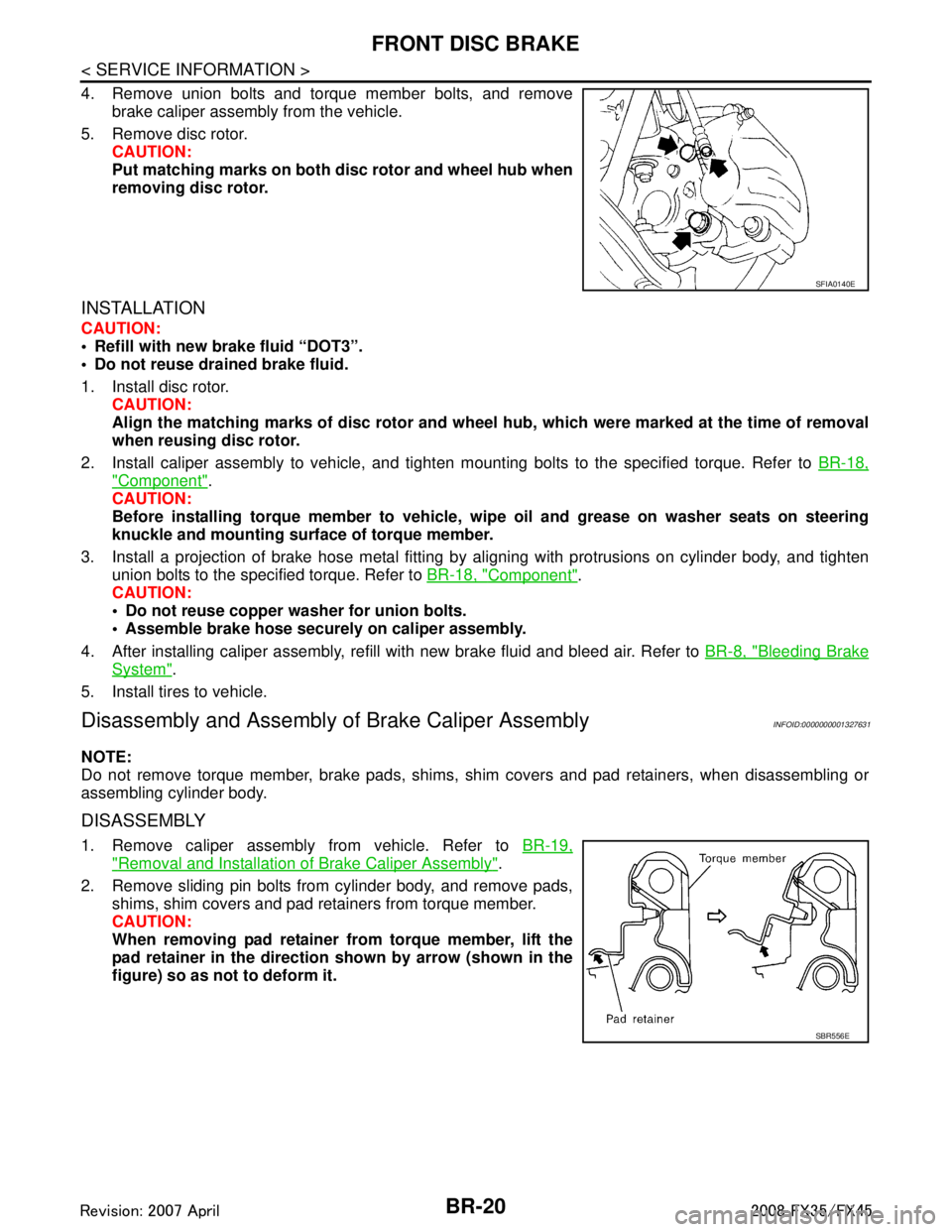
4. Remove union bolts and torque member bolts, and removebrake caliper assembly from the vehicle.
5. Remove disc rotor. CAUTION:
Put matching marks on both disc rotor and wheel hub when
removing disc rotor.
INSTALLATION
CAUTION:
Refill with new brake fluid “DOT3”.
Do not reuse drained brake fluid.
1. Install disc rotor.
CAUTION:
Align the matching marks of disc rotor and wheel hub, which were marked at the time of removal
when reusing disc rotor.
2. Install caliper assembly to vehicle, and tighten mounting bolts to the specified torque. Refer to BR-18,
"Component".
CAUTION:
Before installing torque member to vehicle, wipe oil and grease on washer seats on steering
knuckle and mounting surface of torque member.
3. Install a projection of brake hose metal fitting by aligning with protrusions on cylinder body, and tighten
union bolts to the specified torque. Refer to BR-18, "
Component".
CAUTION:
Do not reuse copper washer for union bolts.
Assemble brake hose securely on caliper assembly.
4. After installing caliper assembly, refill with new brake fluid and bleed air. Refer to BR-8, "
Bleeding Brake
System".
5. Install tires to vehicle.
Disassembly and Assembly of Brake Caliper AssemblyINFOID:0000000001327631
NOTE:
Do not remove torque member, brake pads, shims, shim covers and pad retainers, when disassembling or
assembling cylinder body.
DISASSEMBLY
1. Remove caliper assembly from vehicle. Refer to BR-19,
"Removal and Installation of Brake Caliper Assembly".
2. Remove sliding pin bolts from cylinder body, and remove pads, shims, shim covers and pad retainers from torque member.
CAUTION:
When removing pad retainer fr om torque member, lift the
pad retainer in the direction shown by arrow (shown in the
figure) so as not to deform it.
SFIA0140E
SBR556E
3AA93ABC3ACD3AC03ACA3AC03AC63AC53A913A773A893A873A873A8E3A773A983AC73AC93AC03AC3
3A893A873A873A8F3A773A9D3AAF3A8A3A8C3A863A9D3AAF3A8B3A8C
Page 1010 of 3924

BR-26
< SERVICE INFORMATION >
REAR DISC BRAKE
CAUTION:
Refill with new brake fluid “DOT 3”.
Do not reuse drained brake fluid.
1. Install disc rotor.CAUTION:
Align the matching marks of disc rotor and wheel hub, which were marked at the time of removal
when reusing disc rotor.
2. Install caliper assembly to the vehicle, and tighten bolts to the specified torque. Refer to BR-24, "
Compo-
nent".
CAUTION:
Before installing caliper assembly to the vehicle , wipe off oil and grease on washer seats on axle
assembly and mounting surface of caliper assembly.
3. Install brake hose to caliper assembly and tighten union bolt to the specified torque. Refer to BR-24,
"Component".
CAUTION:
Do not reuse copper washer for union bolts.
Securely install brake hose to protrusion on caliper assembly.
4. After installing caliper assembly, refill with new brake fluid and bleed air. Refer to BR-8, "
Bleeding Brake
System".
5. Install tires to the vehicle.
Disassembly and Assembly of Brake Caliper AssemblyINFOID:0000000001327637
NOTE:
Do not remove torque member, brake pads, shims, shim cover and pad retainers, when disassembling or
assembling cylinder body.
DISASSEMBLY
1. Remove sliding pin bolts, and then remove brake pads, shims, shim cover, and pad retainer from torque
member and cylinder.
CAUTION:
Do not drop brake pads, shims, shim cover and pad retainer from torque member.
2. Remove sliding pin boot from torque member.
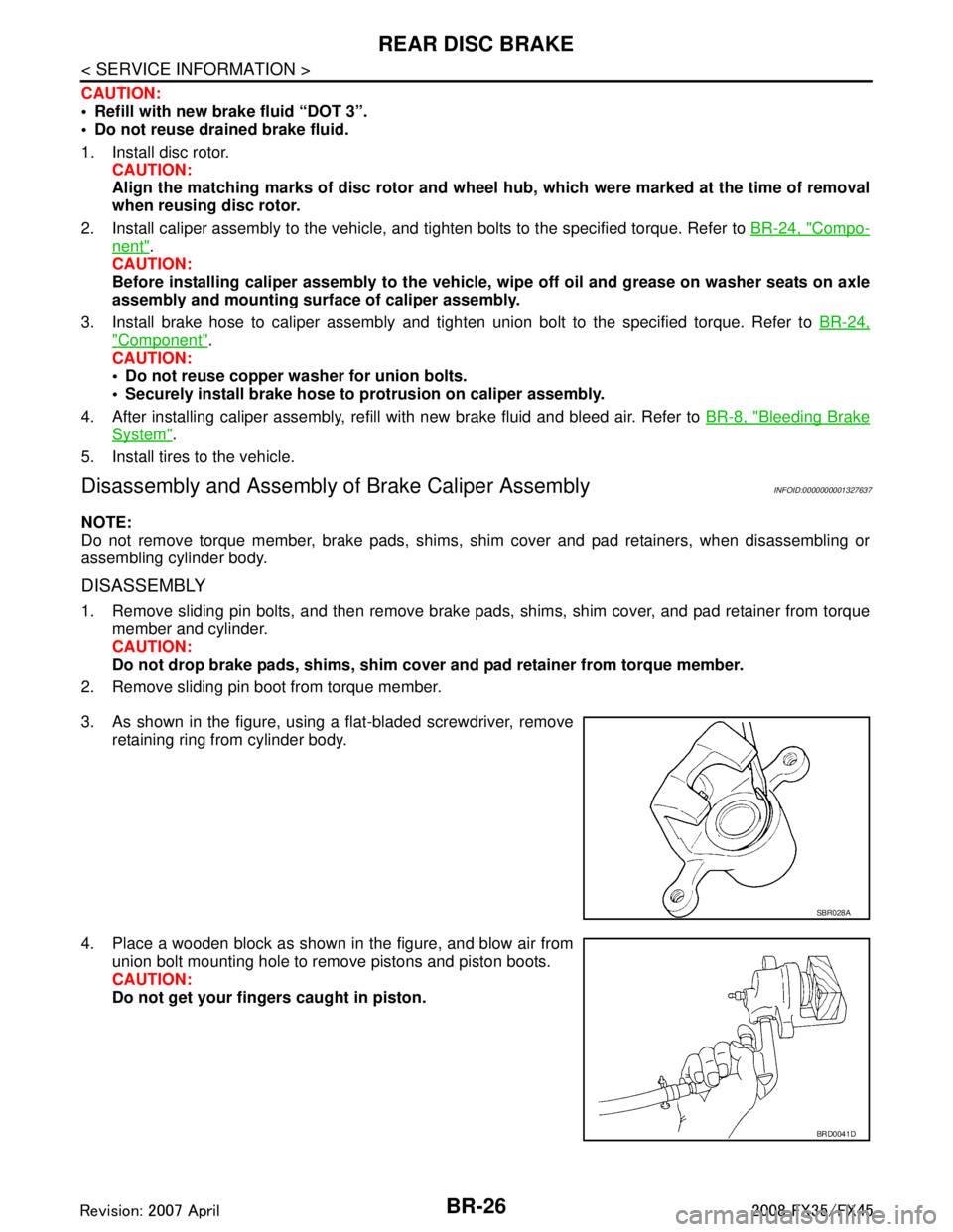
3. As shown in the figure, using a flat-bladed screwdriver, remove retaining ring from cylinder body.
4. Place a wooden block as shown in the figure, and blow air from union bolt mounting hole to remove pistons and piston boots.
CAUTION:
Do not get your fingers caught in piston.
SBR028A
BRD0041D
3AA93ABC3ACD3AC03ACA3AC03AC63AC53A913A773A893A873A873A8E3A773A983AC73AC93AC03AC3
3A893A873A873A8F3A773A9D3AAF3A8A3A8C3A863A9D3AAF3A8B3A8C
Page 1552 of 3924
![INFINITI FX35 2008 Service Manual
EC-312
< SERVICE INFORMATION >[VQ35DE]
DTC P0300, P0301,
P0302, P0303, P0304, P0305, P0306 MULTIPLE CYLINDER
MISFIRE, NO. 1 - 6 CYLINDER MISFIRE
Check the initial spark plug for fouling, etc.
OK o INFINITI FX35 2008 Service Manual
EC-312
< SERVICE INFORMATION >[VQ35DE]
DTC P0300, P0301,
P0302, P0303, P0304, P0305, P0306 MULTIPLE CYLINDER
MISFIRE, NO. 1 - 6 CYLINDER MISFIRE
Check the initial spark plug for fouling, etc.
OK o](/manual-img/42/57017/w960_57017-1551.png)
EC-312
< SERVICE INFORMATION >[VQ35DE]
DTC P0300, P0301,
P0302, P0303, P0304, P0305, P0306 MULTIPLE CYLINDER
MISFIRE, NO. 1 - 6 CYLINDER MISFIRE
Check the initial spark plug for fouling, etc.
OK or NG
OK >> Replace spark plug(s) with standard type one(s). For
spark plug type, refer to MA-17, "
Changing Spark Plugs
(Platinum-Tipped Type)".
NG >> 1. Repair or clean spark plug.
2. GO TO 9.
9.CHECK FUNCTION OF IGNITION COIL-III
1. Reconnect the initial spark plugs.
2. Crank engine for about 3 seconds, and recheck whether spark is generated between the spark plug and the grounded portion.
OK or NG
OK >> INSPECTION END
NG >> Replace spark plug(s) with standard type one(s). For spark plug type, refer to MA-17, "
Changing
Spark Plugs (Platinum-Tipped Type)".
10.CHECK COMPRESSION PRESSURE
Check compression pressure. Refer to EM-100, "
On-Vehicle Service".
OK or NG
OK >> GO TO 11.
NG >> Check pistons, piston rings, valves, valve seats and cylinder head gaskets.
11 .CHECK FUEL PRESSURE
1. Install all removed parts.
2. Release fuel pressure to zero. Refer to EC-87, "
Fuel Pressure Check".
3. Install fuel pressure gauge and check fuel pressure. Refer to EC-87, "
Fuel Pressure Check".
OK or NG
OK >> GO TO 13.
NG >> GO TO 12.
12.DETECT MALFUNCTIONING PART
Check the following.
Fuel pump and circuit (Refer to EC-558
.)
Fuel pressure regulator (Refer to EC-87, "
Fuel Pressure Check".)
Fuel lines (Refer to MA-15, "
Checking Fuel Line".)
Fuel filter for clogging
>> Repair or replace.
13.CHECK IGNITION TIMING
Check the following items. Refer to EC-80, "
Basic Inspection".
OK or NG
OK >> GO TO 14.
SEF156I
Spark should be generated.
At idle: Approximately 350 kPa (3.57 kg/cm
2, 51 psi)
Items Specifications
Target idle speed 650 ± 50 rpm (in P or N position)
Ignition timing 15 ± 5 ° BTDC (in P or N position)
3AA93ABC3ACD3AC03ACA3AC03AC63AC53A913A773A893A873A873A8E3A773A983AC73AC93AC03AC3
3A893A873A873A8F3A773A9D3AAF3A8A3A8C3A863A9D3AAF3A8B3A8C
Page 2139 of 3924
![INFINITI FX35 2008 Service Manual
DTC P0300 - P0308 MULTIPLE CYLINDER MISFIRE, NO. 1 - 8 CYLINDER MIS-
FIRE
EC-899
< SERVICE INFORMATION > [VK45DE]
C
D
E
F
G H
I
J
K L
M A
EC
NP
O
NG >> GO TO 7.
7.CHECK FUNCTION OF
IGNITION COIL-II
INFINITI FX35 2008 Service Manual
DTC P0300 - P0308 MULTIPLE CYLINDER MISFIRE, NO. 1 - 8 CYLINDER MIS-
FIRE
EC-899
< SERVICE INFORMATION > [VK45DE]
C
D
E
F
G H
I
J
K L
M A
EC
NP
O
NG >> GO TO 7.
7.CHECK FUNCTION OF
IGNITION COIL-II](/manual-img/42/57017/w960_57017-2138.png)
DTC P0300 - P0308 MULTIPLE CYLINDER MISFIRE, NO. 1 - 8 CYLINDER MIS-
FIRE
EC-899
< SERVICE INFORMATION > [VK45DE]
C
D
E
F
G H
I
J
K L
M A
EC
NP
O
NG >> GO TO 7.
7.CHECK FUNCTION OF
IGNITION COIL-II
1. Turn ignition switch OFF.
2. Disconnect spark plug and connect a known-good spark plug.
3. Crank engine for about three seconds, and recheck whether spark is generated between the spark plug and the grounded metal portion.
OK or NG
OK >> GO TO 8.
NG >> Check ignition coil, power transistor and their circuits. Refer to EC-1166
.
8.CHECK SPARK PLUG
Check the initial spark plug for fouling, etc.
OK or NG
OK >> Replace malfunctioning spark plug(s) with standard type one(s). For spark plug type, refer to EM-188
.
NG >> 1. Repair or clean spark plug.
2. GO TO 9.
9.CHECK FUNCTION OF IGNITION COIL-III
1. Reconnect the initial spark plugs.
2. Crank engine for about three seconds, and recheck whether spark is generated between the spark plug and the grounded portion.
OK or NG
OK >> INSPECTION END
NG >> Replace malfunctioning spark plug(s) with standard type one(s). For spark plug type, refer to EM-
188.
10.CHECK COMPRESSION PRESSURE
Check compression pressure. Refer to EM-226, "
On-Vehicle Service".
OK or NG
OK >> GO TO 11.
NG >> Check pistons, piston rings, valves, valve seats and cylinder head gaskets.
11 .CHECK FUEL PRESSURE
1. Install all removed parts.
2. Release fuel pressure to zero. Refer to EC-665, "
Fuel Pressure Check".
3. Install fuel pressure gauge and check fuel pressure. Refer to EC-665, "
Fuel Pressure Check".
OK or NG
OK >> GO TO 13.
NG >> GO TO 12.
12.DETECT MALFUNCTIONING PART
Check the following.
Fuel pump and circuit (Refer to EC-1155
.)
Fuel pressure regulator (Refer to EC-665, "
Fuel Pressure Check".)
Spark should be generated.
SEF156I
Spark should be generated.
At idling: Approximate
ly 350 kPa (3.57 kg/cm
2, 51 psi)
3AA93ABC3ACD3AC03ACA3AC03AC63AC53A913A773A893A873A873A8E3A773A983AC73AC93AC03AC3
3A893A873A873A8F3A773A9D3AAF3A8A3A8C3A863A9D3AAF3A8B3A8C
Page 2562 of 3924
![INFINITI FX35 2008 Service Manual
EM-78
< SERVICE INFORMATION >[VQ35DE]
TIMING CHAIN
Do not overtighten slack guide
mounting bolts. It is normal
for a gap to exist under the bo lt seats when mounting bolts
are tightened to the speci INFINITI FX35 2008 Service Manual
EM-78
< SERVICE INFORMATION >[VQ35DE]
TIMING CHAIN
Do not overtighten slack guide
mounting bolts. It is normal
for a gap to exist under the bo lt seats when mounting bolts
are tightened to the speci](/manual-img/42/57017/w960_57017-2561.png)
EM-78
< SERVICE INFORMATION >[VQ35DE]
TIMING CHAIN
Do not overtighten slack guide
mounting bolts. It is normal
for a gap to exist under the bo lt seats when mounting bolts
are tightened to the specification.
9. Install the timing chain tensioner (primary) with the following procedure:
a. Pull plunger stopper tab up (or turn lever downward) so as to remove plunger stopper tab from the rachet of plunger.
NOTE:
Plunger stopper tab and lever are synchronized.
b. Push plunger into the inside of tensioner body.
c. Hold plunger in the fully compressed position by engaging plunger stopper tab with the tip of ratchet.
d. To secure lever, insert stopper pin through hole of lever into ten- sioner body hole.
The lever parts and the tab are synchronized. Therefore, theplunger will be secured under this condition.
NOTE:
Figure shows the example of 1.2 mm (0.047 in) diamet er thin screwdriver being used as the stopper pin.
e. Install timing chain tensioner (primary). Remove any dirt and foreign materials completely from theback and the mounting surfaces of timing chain tensioner (pri-
mary).
f. Pull out stopper pin after installing, and then release plunger.
10. Make sure again that the mating marks on sprockets and timing chain have not slipped out of alignment.
11. Install new O-rings on rear timing chain case.
12. Install new front oil seal on front timing chain case. Apply new engine oil to both oil seal lip and dust seal lip.
PBIC2633E
PBIC3568E
PBIC3569E
PBIC2548E
3AA93ABC3ACD3AC03ACA3AC03AC63AC53A913A773A893A873A873A8E3A773A983AC73AC93AC03AC3
3A893A873A873A8F3A773A9D3AAF3A8A3A8C3A863A9D3AAF3A8B3A8C
Page 2719 of 3924
![INFINITI FX35 2008 Service Manual
CYLINDER HEADEM-235
< SERVICE INFORMATION > [VK45DE]
C
D
E
F
G H
I
J
K L
M A
EM
NP
O
VALVE SEAT REPLACEMENT
When valve seat is removed, replace with
oversized [0.5 mm (0.020 in)] valve seat.
1. Bore INFINITI FX35 2008 Service Manual
CYLINDER HEADEM-235
< SERVICE INFORMATION > [VK45DE]
C
D
E
F
G H
I
J
K L
M A
EM
NP
O
VALVE SEAT REPLACEMENT
When valve seat is removed, replace with
oversized [0.5 mm (0.020 in)] valve seat.
1. Bore](/manual-img/42/57017/w960_57017-2718.png)
CYLINDER HEADEM-235
< SERVICE INFORMATION > [VK45DE]
C
D
E
F
G H
I
J
K L
M A
EM
NP
O
VALVE SEAT REPLACEMENT
When valve seat is removed, replace with
oversized [0.5 mm (0.020 in)] valve seat.
1. Bore out old seat until it collapses. Boring shoul d not continue beyond the bottom face of the seat recess
in cylinder head. Set the machine depth stop to ensure this. Refer to EM-266, "
Standard and Limit".
CAUTION:
Prevent to scratch cylinder head by excessive boring.
2. Ream cylinder head recess diameter for service valve seat.
Be sure to ream in circles concentric to valve guide center.This will enable valve to fit correctly.
3. Heat cylinder head to 110 to 130 °C (230 to 266 °F) by soaking in
heated oil.
4. Provide valve seats cooled well with dry ice. Force fit valve seat into cylinder head. CAUTION:
Avoid directly touching cold valve seats.
Cylinder head contains heat. Wh en working, wear protective equipment to avoid getting burned.
5. Using valve seat cutter set (commercial service tool) or valve seat grinder, finish seat to the specified dimensions. Refer to
EM-266, "
Standard and Limit".
CAUTION:
When using valve seat cutter, firmly grip cutter handle with
both hands. Then, press on the contacting surface all
around the circumference to cu t in a single drive. Improper
pressure on with cutter or cu tting many different times may
result in stage valve seat.
6. Using compound, grind to adjust valve fitting.
7. Check again for normal contact. Refer to "VALVE SEAT CONTACT".
VALVE SPRING SQUARENESS
Oversize (Service) [0.5 mm (0.020 in)] Intake : 37.500 - 37.516 mm (1.4764 - 1.4770 in)
Exhaust : 32.700 - 32.716 mm (1.2874 - 1.2880 in)
SEM795A
SEM008A
SEM934C
3AA93ABC3ACD3AC03ACA3AC03AC63AC53A913A773A893A873A873A8E3A773A983AC73AC93AC03AC3
3A893A873A873A8F3A773A9D3AAF3A8A3A8C3A863A9D3AAF3A8B3A8C
Page 3539 of 3924

RF-24
< SERVICE INFORMATION >
SUNROOF
SUNROOF UNIT ASSEMBLY
Removal
CAUTION:
Always work with a helper.
When taking sunroof unit out, use clothes to protect the seats and trim from damage.
After installing the sunroof un it and glass lid, be sure to perform the leakage test and make sure
there is no malfunction.
1. Tilt up glass lid.
2. Remove the headlining. Refer to EI-43, "
Component Parts Location".
3. Disconnect drain hoses.
4. Remove glass lid. Refer to RF-22, "
Removal and Installation".
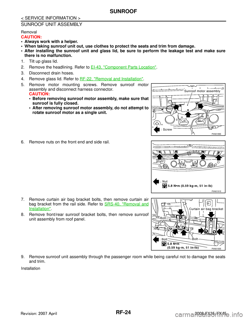
5. Remove motor mounting screws. Remove sunroof motor assembly and disconnect harness connector.
CAUTION:
Before removing sunroof motor assembly, make sure thatsunroof is fully closed.
After removing sunroof motor assembly, do not attempt to
rotate sunroof motor as a single unit.
6. Remove nuts on the front end and side rail.
7. Remove curtain air bag bracket bolts, then remove curtain air bag bracket from the rail side. Refer to SRS-40, "
Removal and
Installation".
8. Remove front/rear sunroof bracket bolts, then remove sunroof unit assembly from roof panel.
9. Remove sunroof unit assembly through the passenger room while being careful not to damage the seats
and trim.
Installation
PIIA6189E
PIIA6191E
PIIA6193E
3AA93ABC3ACD3AC03ACA3AC03AC63AC53A913A773A893A873A873A8E3A773A983AC73AC93AC03AC3
3A893A873A873A8F3A773A9D3AAF3A8A3A8C3A863A9D3AAF3A8B3A8C