2008 INFINITI FX35 automatic transmission fluid
[x] Cancel search: automatic transmission fluidPage 74 of 3924

AT-1
TRANSMISSION/TRANSAXLE
DE
F
G H
I
J
K L
M
SECTION AT
A
B
AT
N
O P
CONTENTS
AUTOMATIC TRANSMISSION
SERVICE INFORMATION .. ..........................5
INDEX FOR DTC ............................................ .....5
Alphabetical Index ............................................... ......5
DTC No. Index ..........................................................5
PRECAUTIONS ...................................................7
Precaution for Supplemental Restraint System
(SRS) "AIR BAG" and "SEAT BELT PRE-TEN-
SIONER" ............................................................. ......
7
Precaution for On Board Diagnosis (OBD) System
of A/T and Engine .....................................................
7
Precaution .................................................................7
Service Notice or Precaution .....................................8
PREPARATION ...................................................9
Special Service Tool ........................................... ......9
Commercial Service Tool ..........................................9
A/T FLUID ...........................................................11
Changing A/T Fluid ............................................. ....11
Checking A/T Fluid ..................................................11
A/T Fluid Cooler Cleaning .......................................13
A/T CONTROL SYSTEM ....................................16
Cross-Sectional View (2WD Models) .................. ....16
Cross-Sectional View (VQ35DE Models for AWD) ....17
Cross-Sectional View (VK45DE Models for AWD) ....18
Shift Mechanism .................................................. ....18
TCM Function ..........................................................29
CAN Communication ...............................................30
Input/Output Signal of TCM .....................................31
Line Pressure Control .............................................31
Shift Control ............................................................33
Lock-up Control .......................................................34
Engine Brake Control ..............................................35
Control Valve ...........................................................36
ON BOARD DIAGNOSTIC (OBD) SYSTEM ......38
Introduction ......................................................... ....38
OBD-II Function for A/T System ..............................38
One or Two Trip Detection Logic of OBD-II ............38
OBD-II Diagnostic Trouble Code (DTC) .............. ....38
Malfunction Indicator Lamp (MIL) ............................40
TROUBLE DIAGNOSIS ....................................41
DTC Inspection Priority Chart ..................................41
Fail-Safe ..................................................................41
How to Perform Trouble Diagnosis for Quick and
Accurate Repair .......................................................
42
A/T Electrical Parts Location ...................................48
Circuit Diagram ........................................................49
Inspections Before Trouble Diagnosis .....................49
Road Test ................................................................53
Vehicle Speed at Which Gear Shifting Occurs ........58
Vehicle Speed at Which Lock-up Occurs/Releas-
es .............................................................................
58
Symptom Chart ........................................................59
TCM Input/Output Signal Reference Value .............83
CONSULT-III Function (TRANSMISSION) ..............84
Diagnosis Procedure without CONSULT-III ............91
DTC U1000 CAN COMMUNICATION LINE .....94
Description ........................................................... ....94
On Board Diagnosis Logic .......................................94
Possible Cause ........................................................94
DTC Confirmation Procedure ..................................94
Wiring Diagram - AT - CAN .....................................95
Diagnosis Procedure ...............................................96
DTC P0615 START SIGNAL CIRCUIT .............97
Description ...............................................................97
CONSULT-III Reference Value in Data Monitor
Mode ........................................................................
97
On Board Diagnosis Logic .......................................97
Possible Cause ........................................................97
DTC Confirmation Procedure ..................................97
Wiring Diagram - AT - STSIG ..................................98
Diagnosis Procedure ...............................................99
DTC P0700 TCM .............................................101
Description .............................................................101
On Board Diagnosis Logic .....................................101
3AA93ABC3ACD3AC03ACA3AC03AC63AC53A913A773A893A873A873A8E3A773A983AC73AC93AC03AC3
3A893A873A873A8F3A773A9D3AAF3A8A3A8C3A863A9D3AAF3A8B3A8C
Page 81 of 3924

AT-8
< SERVICE INFORMATION >
PRECAUTIONS
After performing each TROUBLE DIAGNOSIS, perform “DTC
(Diagnostic Trouble Code) Confirmation Procedure”.
If the repair is completed the DTC should not be displayed in
the “DTC Confirmation Procedure”.
Always use the specified brand of ATF. Refer to MA-9, "
Fluids and Lubricants".
Use lint-free paper not cloth rags during work.
After replacing the ATF, dispose of the waste oil using the methods prescribed by law, ordinance, etc.
Before proceeding with disassembly, thoroughly clean the out side of the transmission. It is important to pre-
vent the internal parts from becoming cont aminated by dirt or other foreign matter.
Disassembly should be done in a clean work area.
Use lint-free paper or towels for wiping parts clean. Common shop rags can leave fibers that could interfere
with the operation of the transmission.
Place disassembled parts in order for easier and proper assembly.
All parts should be carefully cleansed with a general purpose, non-flammable solvent before inspection or
reassembly.
Gaskets, seals and O-rings should be replaced any time the transmission is disassembled.
It is very important to perform functional tests whenever they are indicated.
The valve body contains precision parts and requires extreme care when parts are removed and serviced. Place disassembled valve body parts in order for easier and proper assembly. Care will also prevent springs
and small parts from becoming scattered or lost.
Properly installed valves, sleeves, plugs, etc. will s lide along bores in valve body under their own weight.
Before assembly, apply a coat of recommended ATF to all parts. Apply petroleum jelly to protect O-rings and
seals, or hold bearings and washers in place during assembly. Do not use grease.
Extreme care should be taken to avoid damage to O-rings, seals and gaskets when assembling.
After overhaul, refill the transmission with new ATF.
When the A/T drain plug is removed, only some of t he ATF is drained. Old ATF will remain in torque con-
verter and ATF cooling system.
Always follow the procedures under “Changing A/T Fluid” in the AT section when changing A/T fluid. Refer to
AT- 11 , "
Changing A/T Fluid", AT- 11 , "Checking A/T Fluid".
Service Notice or PrecautionINFOID:0000000001327125
ATF COOLER SERVICE
If ATF contains frictional material (clutches, bands, etc. ), or if an A/T is repaired, overhauled, or replaced,
inspect and clean the A/T fluid cooler mounted in the radiat or or replace the radiator. Flush cooler lines using
cleaning solvent and compressed air after repair. For A/T fluid cooler cleaning procedure, refer to AT-13, "
A/T
Fluid Cooler Cleaning". For radiator replacement, refer to CO-13 (for VQ35DE), CO-40 (for VK45DE).
OBD-II SELF-DIAGNOSIS
A/T self-diagnosis is performed by the TCM in comb ination with the ECM. The results can be read through
the blinking pattern of the A/T CHECK indicator or the malfunction indicator lamp (MIL). Refer to the table on
AT-84, "
CONSULT-III Function (TRANSMISSION)" for the indicator used to display each self-diagnostic
result.
The self-diagnostic results indicated by the MIL ar e automatically stored in both the ECM and TCM memo-
ries.
Always perform the procedure on AT-38, "
OBD-II Diagnostic Trouble Code (DTC)" to complete the
repair and avoid unnecessary blinking of the MIL.
For details of OBD-II, refer to EC-54
(for VQ35DE) or EC-632 (for VK45DE).
Certain systems and components, especially those re lated to OBD, may use the new style slide-lock-
ing type harness connector. For descrip tion and how to disconnect, refer to PG-68
.
SEF217U
3AA93ABC3ACD3AC03ACA3AC03AC63AC53A913A773A893A873A873A8E3A773A983AC73AC93AC03AC3
3A893A873A873A8F3A773A9D3AAF3A8A3A8C3A863A9D3AAF3A8B3A8C
Page 102 of 3924

A/T CONTROL SYSTEMAT-29
< SERVICE INFORMATION >
DE
F
G H
I
J
K L
M A
B
AT
N
O P
TCM FunctionINFOID:0000000001327135
The function of the TCM is to:
Receive input signals sent from various switches and sensors.
Determine required line pressure, shifting point, lock-up operation, and engine brake operation.
Send required output signals to the respective solenoids.
CONTROL SYSTEM OUTLINE
The automatic transmission senses vehicle operating condi tions through various sensors or signals. It always
controls the optimum shift position and reduces shifting and lock-up shocks.
1. Front brake 2. Input clutch 3. Direct clutch
4. High and low reverse clutch 5. Reverse brake 6. Forward brake
7. Low coast brake 8. 1st one-way clutch 9. Forward one-way clutch
10. 3rd one-way clutch 11. Front sun gear 12. Input shaft
13. Mid internal gear 14. Front internal gear 15. Rear carrier
16. Rear sun gear 17. Mid sun gear 18. Front carrier
19. Mid carrier 20. Rear internal gear 21. Output shaft
22. Parking gear 23. Parking pawl
SCIA1519E
SENSORS (or SIGNALS)
⇒TCM
⇒ACTUATORS
PNP switch
Accelerator pedal position signal
Closed throttle position signal
Wide open throttle position signal
Engine speed signal
A/T fluid temperature sensor
Revolution sensor
Vehicle speed signal
Manual mode switch signal
Stop lamp switch signal
Turbine revolution sensor
ATF pressure switch Shift control
Line pressure control
Lock-up control
Engine brake control
Timing control
Fail-safe control
Self-diagnosis
CONSULT-III co
mmunication
line
Duet-EA control
CAN system Input clutch solenoid valve
Direct clutch solenoid valve
Front brake solenoid valve
High and low reverse clutch sole-
noid valve
Low coast brake solenoid valve
Torque converter clutch solenoid
valve
Line pressure solenoid valve
A/T CHECK indicator lamp
Starter relay
Back-up lamp relay
:
Page 403 of 3924

AT-330
< SERVICE INFORMATION >
SERVICE DATA AND SPECIFICATIONS (SDS)
SERVICE DATA AND SPECIFICATIONS (SDS)
General SpecificationINFOID:0000000001327413
*1: Refer to MA-9, "Fluids and Lubricants".
Vehicle Speed at Which Gear Shifting OccursINFOID:0000000001327414
2WD MODELS
At half throttle, the accelerator opening is 4/8 of the full opening.
AWD MODELS
At half throttle, the accelerator opening is 4/8 of the full opening.Applied model
VQ35DE engine VK45DE engine
2WD AWD
Automatic transmission model RE5R05A
Transmission model code number 91X3A 91X3B 96X1C
Stall torque ratio 2.0 : 1 1.85 : 1
Transmission gear ratio 1st 3.540 3.827
2nd 2.264 2.368
3rd 1.471 1.520
4th 1.000 1.000
5th 0.834 0.834
Reverse 2.370 2.613
Recommended flui d Genuine NISSAN Matic J ATF*1
Fluid capacity 10.3 liter (10-7/8 US qt, 9-1/8 Imp qt)
CAUTION:
Use only Genuine NISSAN Matic J ATF. Do not mix with other ATF.
Using ATF other than Genuine NISSAN Matic J ATF will deteriorate in driveability and A/T durability, and may damage the A/T, which is not covered by the warranty.
Engine model VQ35DE
Throttle position Vehicle speed km/h (MPH)
D
1→ D2D2→D3D3→D4D4→D5D5→D4D4→D3D3→D2D2→D1
Full throttle 68 - 72
(42 - 45) 106 - 114
(66 - 71) 164 - 174
(102 - 108) 235 - 245
(146 - 152) 231 - 241
(144 - 150) 144 - 154
(89 - 96) 89 - 97
(55 - 60) 43 - 47
(27 - 29)
Half throttle 54 - 58
(34 - 36) 84 - 90
(52 - 56) 127 - 135
(79 - 84) 159 - 167
(99 - 104) 104 - 112
(65 - 70) 75 - 83
(47 - 52) 35 - 41
(22 - 25) 11 - 1 5
(7 - 9)
Engine model VQ35DE
Throttle position Vehicle speed km/h (MPH)
D
1→ D2D2→D3D3→D4D4→D5D5→D4D4→D3D3→D2D2→D1
Full throttle 62 - 66
(39 - 41) 96 - 104
(60 - 65) 149 - 159
(93 - 99) 213 - 223
(132 - 139) 209 - 219
(130 - 136) 131 - 141
(81 - 88) 81 - 89
(50 - 55) 39 - 43
(24 - 27)
Half throttle 49 - 53
(30 - 33) 76 - 82
(47 - 51) 115 - 123
(71 - 76) 144 - 152
(89 - 94) 95 - 103
(59 - 64) 67 - 75
(42 - 47) 32 - 38
(20 - 24) 11 - 1 5
(7 - 9)
Engine model VK45DE
Throttle position Vehicle speed km/h (MPH)
D
1→ D2D2→D3D3→D4D4→D5D5→D4D4→D3D3→D2D2→D1
3AA93ABC3ACD3AC03ACA3AC03AC63AC53A913A773A893A873A873A8E3A773A983AC73AC93AC03AC3
3A893A873A873A8F3A773A9D3AAF3A8A3A8C3A863A9D3AAF3A8B3A8C
Page 2866 of 3924

GI-4
< SERVICE INFORMATION >
PRECAUTIONS
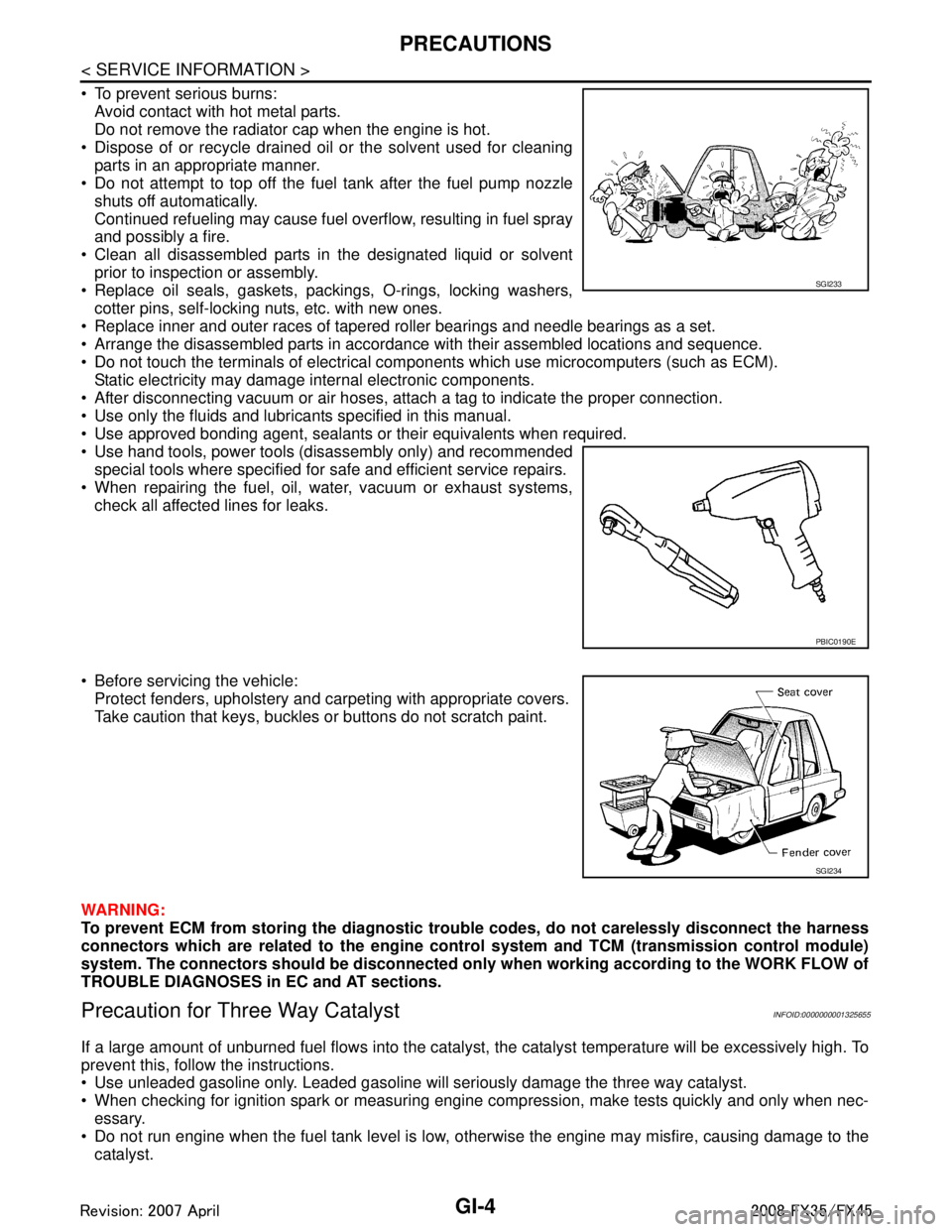
To prevent serious burns:Avoid contact with hot metal parts.
Do not remove the radiator cap when the engine is hot.
Dispose of or recycle drained oil or the solvent used for cleaning parts in an appropriate manner.
Do not attempt to top off the fuel tank after the fuel pump nozzle
shuts off automatically.
Continued refueling may cause fuel overflow, resulting in fuel spray
and possibly a fire.
Clean all disassembled parts in the designated liquid or solvent prior to inspection or assembly.
Replace oil seals, gaskets, packings, O-rings, locking washers, cotter pins, self-locking nuts, etc. with new ones.
Replace inner and outer races of tapered roller bearings and needle bearings as a set.
Arrange the disassembled parts in accordance with their assembled locations and sequence.
Do not touch the terminals of electrical com ponents which use microcomputers (such as ECM).
Static electricity may damage internal electronic components.
After disconnecting vacuum or air hoses, atta ch a tag to indicate the proper connection.
Use only the fluids and lubricants specified in this manual.
Use approved bonding agent, sealants or their equivalents when required.
Use hand tools, power tools (disassembly only) and recommended special tools where specified for safe and efficient service repairs.
When repairing the fuel, oil, water, vacuum or exhaust systems,
check all affected lines for leaks.
Before servicing the vehicle: Protect fenders, upholstery and carpeting with appropriate covers.
Take caution that keys, buckles or buttons do not scratch paint.
WARNING:
To prevent ECM from storing the diagnostic tro uble codes, do not carelessly disconnect the harness
connectors which are related to the engine cont rol system and TCM (transmission control module)
system. The connectors should be disconnected on ly when working according to the WORK FLOW of
TROUBLE DIAGNOSES in EC and AT sections.
Precaution for Three Way CatalystINFOID:0000000001325655
If a large amount of unburned fuel flows into the catalyst , the catalyst temperature will be excessively high. To
prevent this, follow the instructions.
Use unleaded gasoline only. Leaded gasoline will seriously damage the three way catalyst.
When checking for ignition spark or measuring engine compression, make tests quickly and only when nec- essary.
Do not run engine when the fuel tank level is low, otherwise the engine may misfire, causing damage to the
catalyst.
SGI233
PBIC0190E
SGI234
3AA93ABC3ACD3AC03ACA3AC03AC63AC53A913A773A893A873A873A8E3A773A983AC73AC93AC03AC3
3A893A873A873A8F3A773A9D3AAF3A8A3A8C3A863A9D3AAF3A8B3A8C
Page 2882 of 3924

GI-20
< SERVICE INFORMATION >
HOW TO USE THIS MANUAL
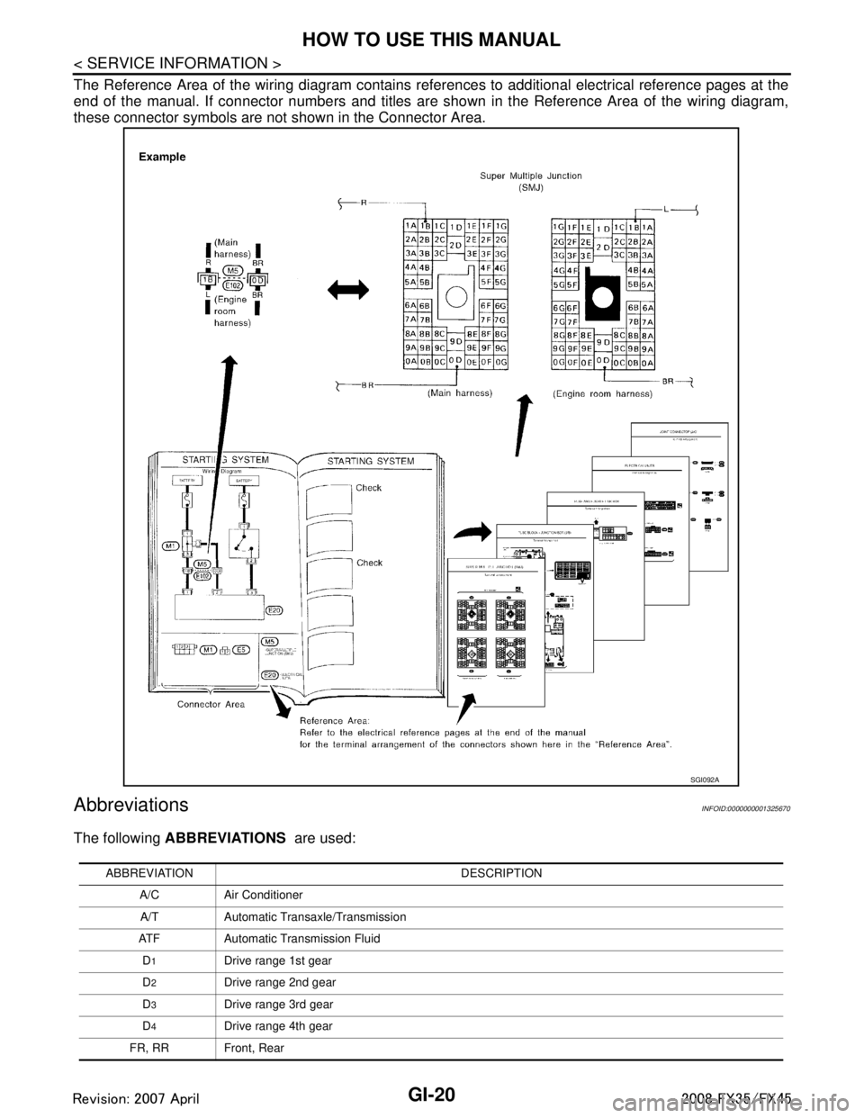
The Reference Area of the wiring diagram contains references to additional electrical reference pages at the
end of the manual. If connector numbers and titles are s hown in the Reference Area of the wiring diagram,
these connector symbols are not shown in the Connector Area.
AbbreviationsINFOID:0000000001325670
The following ABBREVIATIONS are used:
SGI092A
ABBREVIATION DESCRIPTION
A/C Air ConditionerA/T Automatic Transaxle/Transmission
ATF Automatic Transmission Fluid D
1Drive range 1st gear
D
2Drive range 2nd gear
D
3Drive range 3rd gear
D
4Drive range 4th gear
FR, RR Front, Rear
3AA93ABC3ACD3AC03ACA3AC03AC63AC53A913A773A893A873A873A8E3A773A983AC73AC93AC03AC3
3A893A873A873A8F3A773A9D3AAF3A8A3A8C3A863A9D3AAF3A8B3A8C
Page 3323 of 3924

MA-6
< SERVICE INFORMATION >
PERIODIC MAINTENANCE
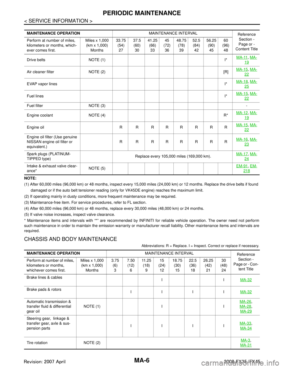
NOTE:
(1) After 60,000 miles (96,000 km) or 48 months, inspect every 15,000 miles (24,000 km) or 12 months. Replace the drive belts if found
damaged or if the auto belt tensioner reading (only for VK45DE engine) reaches the maximum limit.
(2) If operating mainly in dusty conditions, more frequent maintenance may be required.
(3) Maintenance-free item. For service procedures, refer to FL section.
(4) After 60,000 miles (96,000 km) or 48 months, replace every 30,000 miles (48,000 km) or 24 months.
(5) If valve noise increases, inspect valve clearance.
* Maintenance items and intervals with “*” are recommended by INFINITI for reliable vehicle operation. The owner need not perfo rm
such maintenance in order to maintain the emission warranty or manufacturer recall liability. Other maintenance items and inter vals are
required.
CHASSIS AND BODY MAINTENANCE
Abbreviations: R = Replace. I = Inspec t. Correct or replace if necessary.
MAINTENANCE OPERATION MAINTENANCE INTERVAL
Reference
Section -
Page or -
Content Title
Perform at number of miles,
kilometers or months, which-
ever comes first. Miles x 1,000
(km x 1,000) Months 33.75
(54)27 37.5
(60) 30 41.25
(66)33 45
(72) 36 48.75
(78)39 52.5
(84) 42 56.25
(90)45 60
(96) 48
Drive belts NOTE (1) I* MA-11
,
MA-
19
Air cleaner filter NOTE (2) [R] MA-15,
MA-
22
EVAP vapor lines I*MA-18,
MA-
25
Fuel lines I*MA-15,
MA-
22
Fuel filter NOTE (3) -
Engine coolant NOTE (4) R* MA-12
,
MA-
19
Engine oil R R R R R R R R MA-15,
MA-
22
Engine oil filter (Use genuine
NISSAN engine oil filter or
equivalent.) R R RRRRRR
MA-16,
MA-
23
Spark plugs (PLATINUM-
TIPPED type) Replace every 105,000 miles (169,000 km).MA-17,
MA-
24
Intake & exhaust valve clear-
ance* NOTE (5) EM-91,
EM-
218
MAINTENANCE OPERATION MAINTENANCE INTERVAL
Reference
Section -
Page or - Con-
tent Title
Perform at number of miles,
kilometers or months,
whichever comes first. Miles x 1,000
(km x 1,000) Months 3.75
(6)3 7.50
(12) 6 11 . 2 5
(18) 9 15
(24) 12 18.75
(30)15 22.5
(36) 18 26.25
(42)21 30
(48) 24
Brake lines & cables IIMA-32
Brake pads & rotors
IIII MA-32
Automatic transmission &
transfer fluid & differential
gear oilNOTE (1) I I MA-26,
MA-28
,
MA-29
Steering gear, linkage &
transfer gear, axle & sus-
pension parts IIII
MA-33
,
MA-34
Tire rotation NOTE (2) MA-3,
MA-31
3AA93ABC3ACD3AC03ACA3AC03AC63AC53A913A773A893A873A873A8E3A773A983AC73AC93AC03AC3
3A893A873A873A8F3A773A9D3AAF3A8A3A8C3A863A9D3AAF3A8B3A8C
Page 3324 of 3924

PERIODIC MAINTENANCEMA-7
< SERVICE INFORMATION >
C
DE
F
G H
I
J
K
M A
B
MA
N
O P
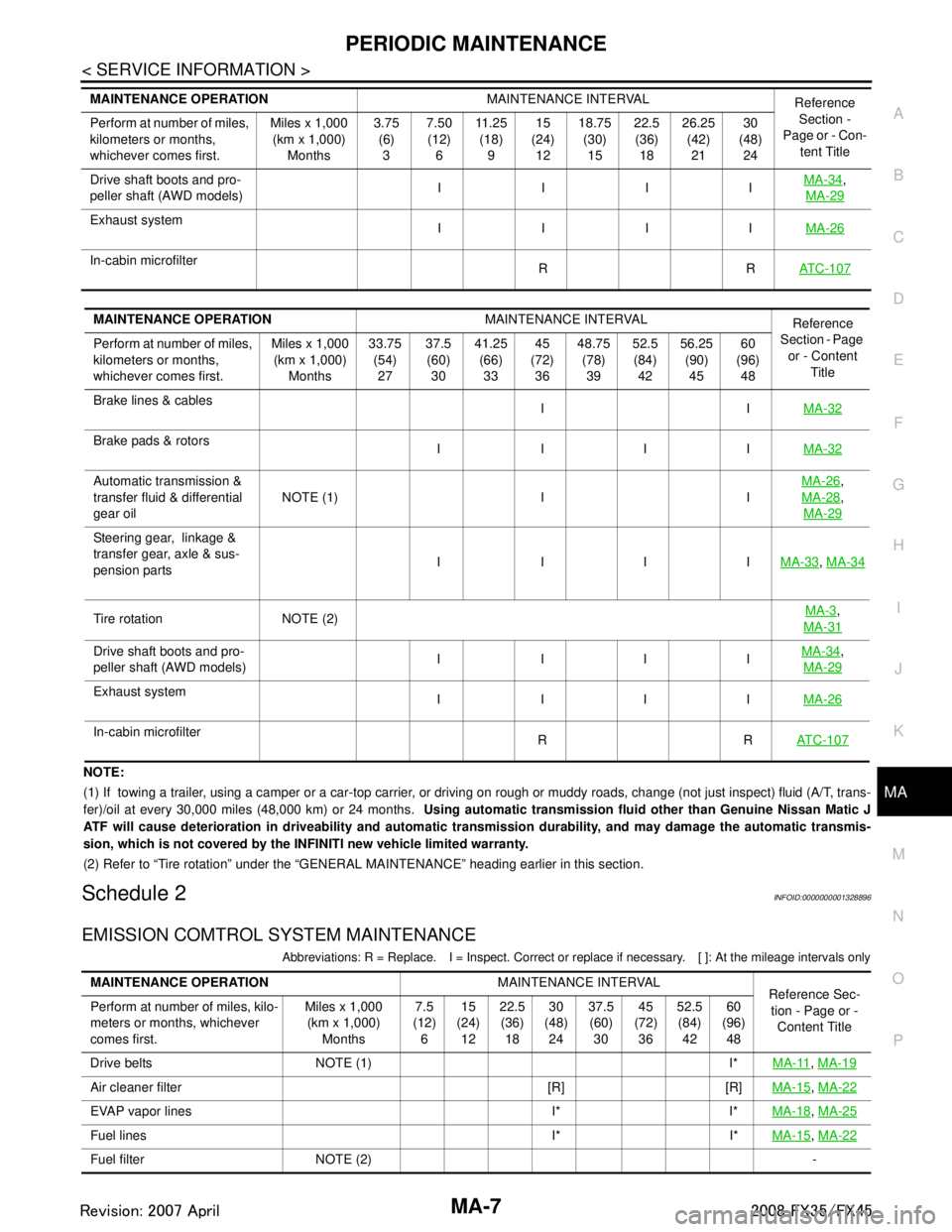
NOTE:
(1) If towing a trailer, using a camper or a car-top carrier, or driving on rough or muddy roads, change (not just inspect) fl uid (A/T, trans-
fer)/oil at every 30,000 miles (48,000 km) or 24 months. Using automatic transmission fluid other than Genuine Nissan Matic J
ATF will cause deterioration in driveability and automatic transmission durability, and may damage the automatic transmis-
sion, which is not covered by the INFINITI new vehicle limited warranty.
(2) Refer to “Tire rotation” under the “GENERAL MAINTENANCE” heading earlier in this section.
Schedule 2INFOID:0000000001328896
EMISSION COMTROL SYSTEM MAINTENANCE
Abbreviations: R = Replace. I = Inspect. Correct or r eplace if necessary. [ ]: At the mileage intervals only
Drive shaft boots and pro-
peller shaft (AWD models) IIII
MA-34,
MA-29
Exhaust system IIII MA-26
In-cabin microfilter
RRAT C - 1 0 7
MAINTENANCE OPERATION MAINTENANCE INTERVAL
Reference
Section -
Page or - Con- tent Title
Perform at number of miles,
kilometers or months,
whichever comes first. Miles x 1,000
(km x 1,000)
Months 3.75
(6)
3 7.50
(12)
6 11 . 2 5
(18)
9 15
(24)
12 18.75
(30)
15 22.5
(36)
18 26.25
(42)
21 30
(48)
24
MAINTENANCE OPERATION MAINTENANCE INTERVAL
Reference
Section - Page
or - Content Title
Perform at number of miles,
kilometers or months,
whichever comes first. Miles x 1,000
(km x 1,000) Months 33.75
(54)27 37.5
(60) 30 41.25
(66)33 45
(72) 36 48.75
(78)39 52.5
(84) 42 56.25
(90)45 60
(96) 48
Brake lines & cables IIMA-32
Brake pads & rotors
IIII MA-32
Automatic transmission &
transfer fluid & differential
gear oilNOTE (1) I I
MA-26,
MA-28
,
MA-29
Steering gear, linkage &
transfer gear, axle & sus-
pension parts IIII
MA-33
, MA-34
Tire rotation NOTE (2) MA-3,
MA-31
Drive shaft boots and pro-
peller shaft (AWD models) IIII MA-34,
MA-29
Exhaust system IIII MA-26
In-cabin microfilter
RRAT C - 1 0 7
MAINTENANCE OPERATION MAINTENANCE INTERVAL
Reference Sec-
tion - Page or - Content Title
Perform at number of miles, kilo-
meters or months, whichever
comes first. Miles x 1,000
(km x 1,000) Months 7.5
(12) 6 15
(24) 12 22.5
(36) 18 30
(48) 24 37.5
(60) 30 45
(72) 36 52.5
(84) 42 60
(96) 48
Drive belts NOTE (1) I* MA-11
, MA-19
Air cleaner filter [R] [R] MA-15, MA-22
EVAP vapor lines I* I* MA-18, MA-25
Fuel lines I* I* MA-15, MA-22
Fuel filter NOTE (2) -
3AA93ABC3ACD3AC03ACA3AC03AC63AC53A913A773A893A873A873A8E3A773A983AC73AC93AC03AC3
3A893A873A873A8F3A773A9D3AAF3A8A3A8C3A863A9D3AAF3A8B3A8C